Table of Contents
Advertisement
Read these instructions carefully before starting assembly and flight.
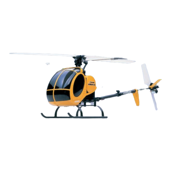
EP Caliber M24
Schweizer 300C
Instruction Manual
Index
1. Safety Precautions
2. Set Contents
3.Items Required for Assembly, Flight and Maintenance
4.Glossary of Items & Features
5.Preparing for Flight
6.Using the Radio Control System
7.Time for Takeoff
8.Tips for Good Flying
9.Maintenance and Replacement of Parts
10.Adjustments
11.Parts List
12.Exploded View Illustration
13.Spare Parts
14.Optional Parts
*Troubleshooting
SAFETY PRECAUTIONS
This radio control model is not a toy!
●This is a high performance model. First time builders should seek advice from experienced
modelers before assembly, or if they do not fully understand any part of the construction.
●Only assemble this model in a place out of children's reach.
●Take sufficient safety precautions. You are responsible for the assembly and safe operation.
●This model is designed for people over 14 years of age. It is not a toy.
Ni-MH
※Specifications are subject to change without notice.
© 2004 KYOSHO CORPORATION
*The product you have purchased is powered by a rechargeable battery. The battery is recyclable.
At the end of its useful life, under various national / state and local laws, it may be illegal to
dispose of this battery into the municipal waste stream. Check with your local solid waste officials
for details in your area for recycling options or proper disposal.
R
THE FINEST RADIO CONTROL MODELS
1~3
4
4
5
6~10
11
12~15
16
17~24
25~26
27
28~30
31~32
32
33
No.20920
Advertisement
Table of Contents

Related Manuals for Kyosho EP Caliber M24


Summary of Contents for Kyosho EP Caliber M24
-
Page 1: Instruction Manual
Read these instructions carefully before starting assembly and flight. EP Caliber M24 Schweizer 300C Instruction Manual THE FINEST RADIO CONTROL MODELS Index 1. Safety Precautions 2. Set Contents 3.Items Required for Assembly, Flight and Maintenance 4.Glossary of Items & Features 5.Preparing for Flight... -
Page 2: Safety Precautions
SAFETY PRECAUTIONS Read this before assembly and operation Use goggles for safety. High speed spinning rotors are very dangerous if This symbol indicates close to the face. CAUTION possible risk of injury or death. This symbol indicates STOP actions you should stop to avoid damage. - Page 3 Keep fingers and hands Batteries and motor become away from rotating hot during and after flight. gears to avoid injury. Allow time to cool down before touching. Antenna point can Do not operate your cause injury. model on the same Keep antenna away band (frequency) as from people's faces and...
-
Page 4: Set Contents
SET CONTENTS S i d e C a n o p y T r a n s mi t t e r B o d y & F u s e l a g e V i s o r Charger(AC)... -
Page 5: Glossary Of Items & Features
GL OSSARY OF I T E MS & F E AT URE S T r a n s mi t t e r An t e n n a Transmitter S e n d s o u t r a d i o s i g n a l . E l e v a t o r T r i m T h r o t t l e T r i m A d j u s t s n e u t r a l p o s i t i o n... -
Page 6: Preparing For Flight
PREPARING FOR FLIGHT ■Charging the Nickel Metal Hydride Battery (Ni-MH) Charging time is about 10 ~ 12 hours. As this charger does not have an automatic cut off function, do not charge for more than 15 hours. (Charging for more than 15 hours is dangerous). A fully charged battery will produce about 5 minutes of flight time. An Ni-MH battery is subject to wear &... - Page 7 ■Body Assembly R e mo v e B o d y . A p p l y D e c a l s ( ) N u mb e r s h o w n i n s i d e b r a c k e t s i s d e c a l f o r o p p o s i t e s i d e . G l u e o n p l a s t i c p a r t s V i s o r I n s t a n t G l u e...
- Page 8 PREPARING FOR FLIGHT ■I n s e r t i n g Ba t t e r i e s Insert new batteries, switch the Transmitter power ON, and red Transmitter and green indicator lamps light up. If batteries are inserted incorrectly or terminals not connected properly, the indicator lamps will not light up, or only the red indicator lamp will light up.
- Page 9 Insert charged Attach Battery Cap. Attach connectors. battery. Battery Battery Cap Connectors ■Power ON Always switch the Transmitter power ON first! Switch transmitter Turn fuselage switch ON Extend antenna Move throttle stick down Power lamp flashes quickly Lamp flashes quickly (every 0.5 sec) Wait for the power lamp to flash slowly Quick flashing of power lamp means (every 2 seconds).
-
Page 10: Preparing For Flight
PREPARING FOR FLIGHT ■Checking Elevator and Aileron Movement Aileron Confirm each part responds according to control inputs. Elevator Elevator Aileron Stick Stick ■Start Move Throttle Stick all the way to the bottom Before pushing Start Button, move Throttle Stick all the way to the bottom. -
Page 11: Using The Radio Control System
USING THE RADIO CONTROL SYSTEM Before flying, understand how the model will respond to control inputs from transmitter. Also, a high degree of skill is needed in controlling this model. ●T h r o t t l e F a s t e r ma i n r o t o r s p e e d f o r a s c e n d i n g . h i g h h i g h l o w... -
Page 12: Time For Takeoff
TIME FOR TAKEOFF T r a c k i n g c a n s l i p e v e n a f t e r b e i n g s h i p p e d f r o m t h e Pre-Flight Checks and Adjustment (every flight) f a c t o r y . - Page 13 Taking Off Flight is not possible in more than light breeze. K e e p e l b o w s d o w n a n d e x t e n d F a c e t h e mo d e l i n t o t h e w i n d . t h e a n t e n n a .
- Page 14 T I ME F OR T AKE OF F G r a d u a l l y i n c r e a s e h e i g h t , a n d l a n d Ma i n t a i n mi d - a i r p o s i t i o n f o r a i n f o r w a r d p o s i t i o n s .
- Page 15 I f t h e e i t h e r o f t h e f o l l o w i n g o c c u r s , s w i t c h t h e p o w e r O F F a n d u n p l u g Changing Battery t h e c o n n e c t o r s i n t h e o r d e r s h o w n b e l o w .
-
Page 16: Tips For Good Flying
TIPS FOR GOOD FLYING P r a c t i c e h o v e r i n g f r o m d i f f e r e n t P r a c t i c e mo v i n g f o r w a r d / b a c k w a r d , s t a n d i n g p o s i t i o n s . -
Page 17: Maintenance And Replacement Of Parts
MAINTENANCE AND REPLACEMENT OF PARTS I f f l i g h t t i me s a r e g e t t i n g s h o r t e r , b a t t e r y c a p a c i t y ma y b e Battery Discharge r e d u c e d ( me mo r y e f f e c t ) . - Page 18 MAINTENANCE AND REPLACEMENT OF PARTS Mo t o r i s s u b j e c t t o w e a r a n d t e a r . U s e f o l l o w i n g r e p l a c e me n t t i me f r a me s a s a g u i d e .
- Page 19 Change as per illustration. Changing Main Rotor ) 2 x10mm( Attach so main Rotor Main Rotor moves freely front and back Note direction Washer Washer 2mm Nylon Nut Main Rotor Note direction Back 2mm Nylon Nut Front Change brace if damaged. Changing Brace Remove Antenna Change Brace...
- Page 20 MAINTENANCE AND REPLACEMENT OF PARTS C h a n g e a s p e r i l l u s t r a t i o n Changing Main Mast R e mo v e s c r e w s P u l l P i n o u t 2 x 5 mmT P (t r u s s )...
- Page 21 R e mo v e Ma i n G e a r Mo v e 1 . 5 x 1 0 mm S p r i n g P i n t o o n e s i d e P u l l o u t 1 .
- Page 22 MAINTENANCE AND REPLACEMENT OF PARTS I f mo d e l i s u n s t a b l e o r u n c o n t r o l l a b l e , t h e d a mp e r s ma y b e w o r n o r d a ma g e d . Changing Damper C h e c k a n d r e p l a c e i f r e q u i r e d .
- Page 23 A s s e mb l e a s p e r i l l u s t r a t i o n Assembling Swash Plate 2 x 4 mmT P (r o u n d h e a d ) h o l e S w a s h S w a s h P l a t e C...
-
Page 24: Maintenance And Replacement Of Parts
MAINTENANCE AND REPLACEMENT OF PARTS Tail Stopper H o l d w i t h t w o f i n g e r s . Removal Push with thumb Tail Stopper and remove. Hold with thumb. Attaching Tail Stopper Note direction Tail Stopper t o p s i d e... -
Page 25: Adjustments
Adjustments Adjust as per dimensions in illustration. Rod Length 121mm Tail Support End L e n g t h a n d A n g l e Tail Support End Front Back F r o n t a n d b a c k h a v e d i f f e r e n t s i z e s c r e w h o l e s . -
Page 26: Adjustments
ADJUSTMENTS A l i g n p i t c h a n g l e s o f l e f t a n d r i g h t ma i n r o t o r b l a d e s . Tracking Adjustment Attach red tape to rotor A Pitch Rod... -
Page 27: Parts List
PARTS LIST K e y P a r t N a me Q t y . K e y P a r t N a me Q t y . Ma i n R o t o r Ce n t e r Hu b B (T r a i n i n g S a f e t y B a r ) T a i l R o t o r S a f e t y b a r (T r a i n i n g S a f e t y B a r )... - Page 28 EXPLODED VIEW C A 1 0 1 5 2 x 1 0 mm(c a p ) C A 1 0 0 1 C A 1 0 0 7 2 x 5 mmT P (t r u s s ) C A 1 0 0 2 2 x 1 0 mm(c a p )...
- Page 29 C A 1 0 1 4 C A 1 0 1 4 C A 1 0 1 4 C A 1 0 1 4 C A 1 0 3 3 B R G 0 0 7 C A 1 0 1 4 C A 1 0 1 7 C A 1 0 1 4 2 x 6 mmT P (r o u n d h e a d )...
- Page 30 EXPLODED VIEW 2 x 5 mmT P (t r u s s ) C A 1 0 3 0 C A 1 0 2 7 C A 1 0 2 4 2 x 5 mmT P (t r u s s ) C A 1 0 2 3 1 .
-
Page 31: Spare Parts
SPARE PARTS P a r t N o . P a r t N a me C o n t e n t s ( K e y & Q t y . ) C A 1 0 0 1 C e n t e r H u b A s s e mb l y 1 1 1 7 6 0 6 8 6 9 C A 1 0 0 1 - 0 1 C e n t e r H u b... -
Page 32: Spare Parts
SPARE PARTS P a r t N o . P a r t N a me C o n t e n t s ( K e y & Q t y . ) C A 1 0 2 4 T a i l R o t o r C A 1 0 2 5 T a i l S t o p p e r... -
Page 33: Troubleshooting
TROUBLE SHOOTING Condition Cause Correction Sw i tch p o w e r ON a s p e r P.9 P o w e r sw i tch o n tra n smi tte r o f i n stru cti o n ma n u a l . o r fu se l a g e i s n o t ON . - Page 34 THE FINEST RADIO CONTROL MODELS http://www.kyosho.co.jp/ PRINTED IN JAPAN...
Need help?
Do you have a question about the EP Caliber M24 and is the answer not in the manual?
Questions and answers