
Related Manuals for Motorola SLVR L7


Summary of Contents for Motorola SLVR L7
-
Page 1: Index
Level 1 and 2 Service Manual 6809495A77-O Motorola SLVR L7 Digital Wireless Telephone GSM 850/900/1800/1900 MHz GPRS... -
Page 3: Table Of Contents
6809495A77-O Level 1 and 2 Service Manual Contents Motorola SLVR L7 Contents Contents Contents ..................3 Introduction . - Page 4 Contents Motorola SLVR L7 September 23, 2005 6809495A77-O...
-
Page 5: Introduction
Available on a contract basis, Motorola Inc. offers comprehensive maintenance and installation programs that enable customers to meet requirements for reliable, continuous communications. To learn more about the wide range of Motorola service programs, contact your local Motorola products representative or the nearest Customer Service Manager. Product Identification Motorola products are identified by the model number on the housing. -
Page 6: Computer Program Copyrights
The Motorola products described in this manual may include Motorola computer programs stored in semiconductor memories or other media that are copyrighted with all rights reserved worldwide to Motorola. Laws in the United States and other countries preserve for Motorola, Inc. certain exclusive rights to the... -
Page 7: Warranty Service Policy
Customer’s original phone will be repaired but not refurbished as standard. Appointed Motorola Service Hubs will perform warranty and non-warranty field service for level 2 (assemblies) and level 3 (limited PCB component). The Motorola High Technology Centers will perform level 4 (full component) repairs. -
Page 8: Parts Replacement
When ordering replacement parts or equipment, include the Motorola part number and description used in the service manual. When the Motorola part number of a component is not known, use the product model number or other related major assembly along with a description of the related major assembly and of the component in question. -
Page 9: Specifications
Level 1 and 2 Service Manual Specifications Specifications General Function Specification 824-849 MHz Tx Frequency Range GSM 850 869-894 MHz Rx 880-915 MHz Tx (with EGSM) Frequency Range GSM 900 925-960 MHZ Rx 1710-1785 MHz Tx Frequency Range DCS 1800 1805-1880 MHz Rx 1850-1910 MHz Tx Frequency Range PCS 1900... - Page 10 Specifications Motorola SLVR L7 Speech Coding Function Specification Frame Duration 20 ms Block Length 260 bits Classes Class 1 bits = 182 bits; Class 2 bits = 78 bits Bit Rate with FEC Encoding 22.8 kbps September 23, 2005 6809495A77-O...
-
Page 11: Product Overview
Service (SMS) text messaging, and include clock, alarm, datebook, and calculator personal management tools. The telephones feature VibraCall vibrating alert and a selection of ring tones. The Motorola SLVR L7 is a quad-band phone that allows roaming within the 850, 900, 1800 and 1900MHz bands. - Page 12 Product Overview Motorola SLVR L7 Personal Information Management The Motorola SLVR L7 telephones contain a built-in datebook with alarm reminders, message center, and a phonebook. Other Features Detailed descriptions of other features available for the Motorola SLVR L7 wireless telephones are in the appropriate User’s Guide listed in the Related Publications section toward the end of this manual.
-
Page 13: General Operation
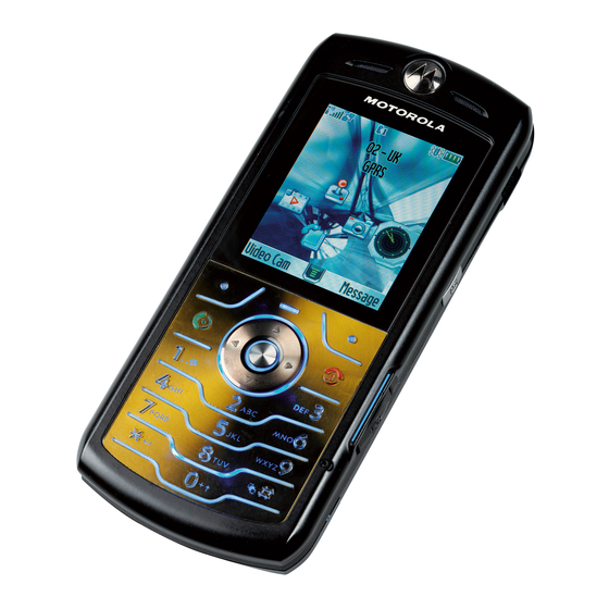
A scroll key allows you to move easily through menus. Liquid Crystal Display (LCD) Motorola SLVR L7 phones feature a 176 x 220 TFT color display offering 7 lines of text, 1 line of icons, and 1 line of prompts. The display provides constant graphical representations of battery capacity and signal strength, as well as the real-time clock. - Page 14 General Operation Motorola SLVR L7 Figure 2 shows common icons displayed on the LCD. 1. Signal 9. Battery Strength Service Provider Level 2. GPRS 8. Ring Style 12:00 040079b 3. PTT News and graphics from your Service Provider 4. Bluetooth 7.
-
Page 15: User Interface Menu Structure
Figure 3. Menu Structure Alert Settings ® Motorola Motorola SLVR L7 phones incorporate the VibraCall discreet vibrating alert that helps to avoid disturbing others when a ringing phone is unacceptable. Alerts can be set to ring only, vibrate only, vibrate then ring, or no ring or vibrate. -
Page 16: Operation
General Operation Motorola SLVR L7 Battery Removal Removing the battery causes the phone to shut down immediately and loose any pending work. For example, (partially entered phonebook entries or outgoing messages). All batteries can cause property damage and/or bodily injury such as burns if a conductive material such as jewelry, keys, or beaded chains touch exposed terminals. -
Page 17: Tools And Test Equipment
Coaxial cable connector removal tool to/from circuit board. 1. To order in North America, contact Motorola Aftermarket and Accessories Division (AAD) by phone at (800) 422-4210 or FAX (800) 622-6210; Internationally, you can reach AAD by phone at (847) 538-8023 FAX (847) 576-3023. -
Page 18: Disassembly
Disassembly Motorola SLVR L7 Disassembly This section describes how to disassemble a Motorola SLVR L7 telephone. Tools and equipment used are listed in Table 1. Many of the integrated devices used in this phone are vulnerable to damage from ESD. Ensure adequate static protection is in place when handling, shipping, and servicing any internal components. -
Page 19: Removing And Replacing The Battery
Level 1 and 2 Service Manual Disassembly Removing and Replacing the Battery Remove the battery cover as described in the procedures. Lift the top end of the battery as indicated by the arrow in Figure 5. Lift the battery up and out of the battery compartment. Battery o50954o Figure 5. -
Page 20: Removing And Replacing The Sim
Disassembly Motorola SLVR L7 Removing and Replacing the SIM Remove the battery cover and battery as described in the procedures. Unlock the SIM holder by sliding it away from the SIM. Lift up the SIM and remove it from the phone (see Figure 6). -
Page 21: Removing And Replacing The Antenna Cap
Level 1 and 2 Service Manual Disassembly Removing and Replacing the Antenna Cap Remove the battery cover, battery and SIM, as described in the procedures. Insert the disassembly tool under each side of the antenna cover to release the antenna cover latches (see Figure 9). Disassembly tool Antenna Cap 051455o... -
Page 22: Removing And Replacing The Transceiver Pc Board Shield
Disassembly Motorola SLVR L7 Removing and Replacing the Transceiver PC Board Shield Remove the battery cover, battery, SIM, and antenna, as described in the procedures. Using a Torx Plus driver with a T6 bit, remove the 6 housing screws from the phone. -
Page 23: September
Level 1 and 2 Service Manual Disassembly To replace, place the PC board shield onto the phone. Ensure the PCB and PCB shield are aligned with the chassis alignment pin. Insert and tighten the 6 T6 screws to a torque setting of 14 Ncm. Do not overtighten. -
Page 24: Removing And Replacing The Transceiver Pc Board
Disassembly Motorola SLVR L7 Removing and Replacing the Transceiver PC Board Remove the battery cover, battery, SIM, and rear housing as described in the procedures.. This product contains static-sensitive devices. Use anti-static handling procedures to prevent ESD and component damage. - Page 25 Level 1 and 2 Service Manual Disassembly Use the coaxial cable extraction tool (see Figure 12) to unseat the coaxial cable connector from the transceiver PC board (see Figure 13). . . Coaxial cable extraction tool 051259o Figure 11. Coaxial Cable Extraction Tool Coaxial cable extraction tool Attach extraction tool opening to...
- Page 26 Disassembly Motorola SLVR L7 Use the disassembly tool to unseat the keypad PC board flex connector from its socket on the Transceiver PC board (see Figure 10) Carefully lift one side of the transceiver PC board out of the phone. Be careful to avoid damage to the two flex cables and the coaxial cable.
-
Page 27: Removing And Replacing The Camera Assembly
Level 1 and 2 Service Manual Disassembly Removing and Replacing the Camera Assembly Remove the battery cover, battery, SIM, antenna, and transceiver PC board as described in the procedures.. This product contains static-sensitive devices. Use anti-static handling procedures to prevent ESD and component damage. The flexible printed cable (FPC) (flex) is easily damaged. - Page 28 Disassembly Motorola SLVR L7 Lift the camera assembly away from the transceiver PC board (see Figure 14). Plastic tweezers Camera assembly 050981o Figure 14. Removing the Camera Assembly Remove the rubber grommet from the camera assembly. To replace, place the rubber camera assembly grommet onto the camera assembly.
-
Page 29: Removing And Replacing The Front Housing
Level 1 and 2 Service Manual Disassembly Removing and Replacing the Front Housing Remove the battery cover, battery, SIM, antenna, and transceiver PC board as described in the procedures. Insert the disassembly between the front housing and the chassis assembly (see Figure 15). -
Page 30: Removing And Replacing The Keypad
Disassembly Motorola SLVR L7 Removing and Replacing the Keypad Remove the battery cover, battery, SIM, rear housing, and transceiver PC board, as described in the procedures. Lift the keypad up from one corner as shown in Figure 16 and remove it from the front housing. -
Page 31: Removing And Replacing The Keypad Pc Board
Level 1 and 2 Service Manual Disassembly Removing and Replacing the Keypad PC Board Remove the battery cover, battery, SIM, antenna, transceiver PC board, and front housing, as described in the procedures. Use the Torx driver with a T3 bit to remove the 2 screws from the Keypad PC board (see Figure 17). - Page 32 Disassembly Motorola SLVR L7 Remove the flex from the chassis Left the keypad PC board away from the phone. To replace, align the flex connector the keypad PC board and gently press the connector until properly seated in the connector socket.
-
Page 33: Removing And Replacing The Antenna
Level 1 and 2 Service Manual Disassembly Removing and Replacing the Antenna Remove the battery cover, battery and SIM, as described in the procedures. Use the plastic tweezers to lift the antenna assembly out of the phone (see Figure 19). Antenna assembly 050986o Figure 19. -
Page 34: Removing And Replacing The Display Module
Disassembly Motorola SLVR L7 Removing and Replacing the Display Module Remove the battery cover, battery, rear housing, and transceiver PC board as described in the procedures. Turn over the chassis assembly and use the metal tweezers to release the six display bracket latches located under the chassis assembly (see Figure 20). - Page 35 Level 1 and 2 Service Manual Disassembly Turn the chassis assembly over and lift the top edge of the display module (see Figure 21). Display module Plastic tweezers 051045o Figure 21. Removing the Display Module Carefully thread the display flex cable through the slot in the chassis assembly and lift the display module away from the chassis.
-
Page 36: Subscriber Identity Module (Sim) And Identification Label
The MSN is an individual unit identity number and remains with the unit throughout its life. The MSN can be used to log and track a phone on Motorola's Service Center Database. The MSN is divided into 4 sections as shown in Figure 22. - Page 37 Level 1 and 2 Service Manual Subscriber Identity Module (SIM) and Identification Label International Mobile Station Equipment Identity (IMEI) The International Mobile station Equipment Identity (IMEI) number is an individual number unique to the PCB and is stored within the unit's memory. The IMEI uniquely identifies an individual mobile station and thereby provides a means for controlling access to GSM networks based on mobile station types or individual units.
-
Page 38: Telephone Identification
Telephone Identification Motorola SLVR L7 Telephone Identification Identification Label Each Motorola GSM phone is labeled with a variety of identifying numbers. Figure 16 describes the current identifying labels. Type approval Mfg by information MOTOROLA INC. FCC ID: IHDT5UV1 EE 3 CANADA: 109 182 230A;... -
Page 39: Troubleshooting
Troubleshooting Troubleshooting Manual Test Mode Motorola M SLVR L7 telephones are equipped with a manual test mode OTOROLA capability. This allows service personnel to verify functionality and perform fault isolation by entering keypad commands. To enter the manual test command mode, a GSM / DCS test SIM must be used. - Page 40 Troubleshooting Motorola SLVR L7 Table 3. Manual Test Commands (Continued) Key Sequence Test Function/Name Remarks 5*0*8 Set audio level 8 5*0*9 Set audio level 9 5*0*10 Set audio level 10 5*0*11 Set audio level 11 5*0*12 Set audio level 12...
-
Page 41: Troubleshooting Chart
Level 1 and 2 Service Manual Troubleshooting Troubleshooting Chart Table 4. Level 1 and 2 Troubleshooting Chart Symptom Probable Cause Verification and Remedy 1. Telephone will not turn on or stay on. a) Battery either discharged or Measure battery voltage across a 50 ohm defective. - Page 42 Troubleshooting Motorola SLVR L7 Table 4. Level 1 and 2 Troubleshooting Chart (Continued) Symptom Probable Cause Verification and Remedy b) Earpiece speaker defective. Temporarily replace the speaker with a known good speaker. Ensure good connection. Place a call and verify improvement in earpiece audio. If fault is cleared, reassemble the phone with the good transceiver board.
-
Page 43: Part Numbers
Level 1 and 2 Service Manual Part Numbers Part Numbers The following section provides a reference for the parts associated with Motorola SLVR L7 telephones. 6809495A77-O September 23, 2005... -
Page 44: Exploded View Diagram
Part Numbers Motorola SLVR L7 Exploded View Diagram 051325o Figure 24. Exploded View Diagram September 23, 2005 6809495A77-O... -
Page 45: Exploded View Parts List
Level 1 and 2 Service Manual Part Numbers Exploded View Parts List Table 5. Parts list Motorola Part Motorola Part Item Description Item Description Number Number AAHN5592A Assy, Front housing 0171065A01 Assy, Chassis 6171080A01 Main Lens AALG4321AA Main PCBA 1371291A01... -
Page 46: Accessories
Bluetooth Speaker Quadrant - HF800 Bluetooth Products SYN0736 Vehicle Power Adapter EMU - VC700 In-Vehicle Solutions SYN0847 Self Install Car Kit - Smart Drive - Motorola In-Vehicle Solutions SYN1134 Self Install Car Kit - Smart Drive+ - Motorola In-Vehicle Solutions SYN1137... - Page 47 Level 1 and 2 Service Manual Part Numbers Table 6. List of Accessories (Continued) Accessory Description Accessory Type Kit Number Smart Cable EMU - Motorola In-Vehicle Solutions SYN1003 Travel Charger EMU Mid-Rate Switcher - Argentina Power Solutions SPN5192 Travel Charger EMU Mid-Rate Switcher - Australia...
-
Page 48: Related Publications
Part Numbers Motorola SLVR L7 Related Publications Motorola Motorola SLVR L7 User’s Guide (English) 68XXXXX105 Programming: Software Upgrade and Flexing Contact your local technical support engineer for information about equipment and procedures for flashing and flexing. September 23, 2005 6809495A77-O... - Page 49 1 and 2 6809495A77-O Level 1 and 2 Service Manual Index Motorola SLVR L7 Index LCD 13 liquid crystal display (LCD) 13 alert settings 15 antenna cap, removing and replacing 21 manual test mode 39 antenna, removing and replacing 33...
- Page 50 Index Motorola SLVR L7 front housing 29 troubleshooting chart 41 keypad PC board 30, 31 SIM 20 Tranceiver PC Board 24 warranty service 7 Tranceiver PC Board Shield 22 replacing antenna 33 antenna cap 21 battery 18, 19 battery cover 18...
- Page 52 MOTOROLA, the Stylized M Logo, and all other trademarks indicated as such herein are trademarks of Motorola, Inc. ® Reg. U.S. Pat. & Tm. Off. © 2005 Motorola, Inc. All rights reserved. Personal Communications Sector, 789 International Parkway, Room S2C Sunrise, FL 33325-6220.
Need help?
Do you have a question about the SLVR L7 and is the answer not in the manual?
Questions and answers