
Related Manuals for Gobler-Hirthmotoren KG 2706

Summary of Contents for Gobler-Hirthmotoren KG 2706
- Page 1 Göbler-Hirthmotoren KG Service manual Engine 2706 Göbler-Hirthmotoren KG, Max-Eyth-Str. 10, D-71726 Benningen, Germany Tel.: 0049-7144-8551-0, Fax: 0049-7144-5415 e-mail: info@hirth-engines.de, internet: www.hirth-engines.de...
- Page 2 Engine Type 2706 Manual Read the operating instructions completely before the assembly of the engine or before starting the engine. In the interest of the ongoing developments of our products, we reserve the right to change the delivery volume in form, technique and supply.
-
Page 3: Table Of Contents
Table of Contents Chapter Topic Page Description of the engine, its systems, and essential technical information Overview of the engine 1.1.1 Model 2706 1.1.2 Description of the carburetion system 1.1.3 Description of the ignition system 1.1.4 Description of the cooling system Installation 1.2.1... - Page 4 Maintenance General 3.1.1 Scope 3.1.2 Common and special tools and initial torque values Service intervals 3.2.1 Daily inspections 3.2.2 Periodic inspections Replacement parts Maintenance procedures 3.4.1 Carburetor 3.4.1.1 Synchronization of carburetors 3.4.1.2 Setting the fuel mixture adjustment screws 3.4.1.3 Cleaning the carburetors 3.4.2.
- Page 5 3.7.4 Engine does not develop full power 3.7.5 Excessive cylinder head temperature Ignition system wiring diagrams Single ignition wiring diagram Dual ignition wiring diagram...
-
Page 6: Description Of The Engine, Its Systems, And
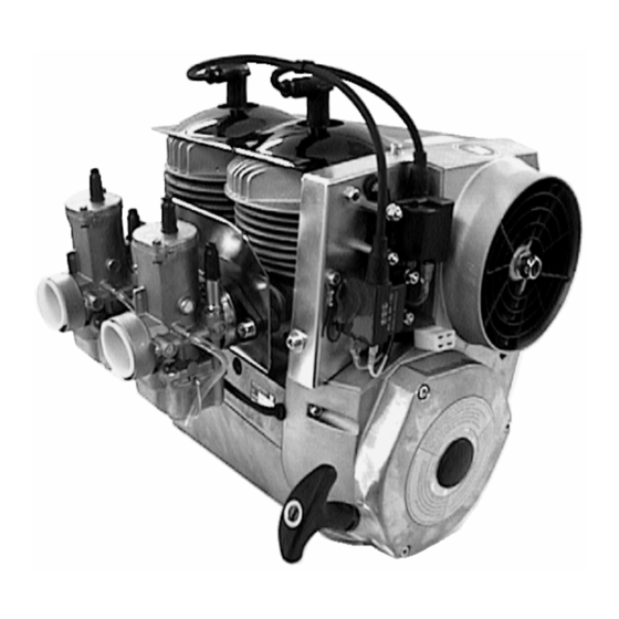
Description of the Engine, Its Systems, and Essential Technical Data 1.1 Overview 1.1.1 Model 2706 The Hirth 2706 engine (Illus. 1.1.1-1), from Göbler-Hirth Engines Ltd., is a fan-cooled, side- regulated, two cylinder inline, two stroke engine. The cylinders consist of an aluminum alloy coated with an abrasion-resistant surface. The cylinders are attached to the crankcase with bolts, washers and hexagonal nuts. -
Page 7: Description Of The Carburetion System
1.1.2 Description of the Carburetion System The fuel mixture system (Illus. 1.1.2-1) of the 2706 engine consistes of two carburetors. Each carburetor is connected to the entry port of the cylinder by an aluminum intake socket and a rubber flange. The aluminum intake socket is screwed on to the cylinder with cylinder bolts and lockwashers and the carburetor is secured in the rubber flange by a hose clamp. - Page 8 Illustration 1.1.3-1 (Single Ignition) Illustration 1.1.3-2 (Dual Ignition) Illustration 1.1.3-3 (View of the ignition side with installed ignition system)
-
Page 9: Description Of The Cooling System
1.1.4 Description of the Cooling System The 2706 engine has a mechanically operated forced air cooling which is transposed on the exhaust side and fixed on the ignition side. (Illus. 1.1.4-1). The fan is mounted inside the fan housing by a cam . It is propelled by a flat belt and a catch, which is attached to the magneto wheel of the ignition. -
Page 10: Airflow To The Engine
The engine should be mounted so that the moment transmitted from the engine to the mount can be on the broadest base as possible [?]. The shock mounts used should be as stiff as possible, because the engine vibration can result in a mounting that is not secure. This leads to problems with the fuel mixture (i.e. -
Page 11: Adjusting The Carburetors
the diaphragm pump. When choosing the impulse line and the fuel line, take care to use rigid lines, which do not expand under pressure. The impulse line should not exceed a maximum length of 150 mm and a minimum inside radius of 6 mm. In any case it is advantageous to position the fuel tank above the engine, since this ensures a certain pressure to the fuel supply. -
Page 12: Engine Instruments
1.3 Engine instruments It is urgently recommended that the cylinder head temperature, the exhaust gas temperature, and the fuel pressure be monitored. Proper adjustment of the engine guarantees its trouble free functioning under the prescribed installation conditions. When engine installation is not carried out by Göbler-Hirth Engines, there are sometimes problems, such as insufficient flow of cool air, a fuel tank installed too low for ascending and descending flight/uphill and downhill driving, and it is absolutely necessary for secure engine operation that the cylinder head temperature, exhaust gas... -
Page 13: Fuel Pressure
The maximum acceptable exhaust gas temperatures mentioned by Göbler-Hirth Engines are based upon the proper positioning and calibration of the measuring devices within the range of these temperatures 1.3.3 Fuel Pressure (see Table 1.5-1) 1.4 Identification Plate The identification plate is on the intake side, upper side of the crankcase . Illustration 1.4-1 (Identification Plate Position) -
Page 14: Technical Data
1.5 Technical Data Table 1.5-1 Manufacurer Göbler-Hirth Engines Ltd. Model 2706 Type [lit. Work process] Two stroke Number of Cylinders 2, in line Diplacement 625 cm Stroke 69 mm Bore 76 mm Compression Ratio 9.5 : 1 Performance 48 kW (65 PS) at 6300 RPM... -
Page 15: Operating The Engine
Chapter 2 Operating the Engine 2.1 General Guidelines It is absolutely necessary to follow the instructions in this chapter in order to achieve long- term, economical, and satisfactory service from the engine. USE ONLY THE PRESCRIBED TYPE OF TWO STROKE OIL AND THE PROPER GRADE OF GASOLINE. -
Page 16: Starting Procedures
Attention ! For safety reasons, it is recommended that the following items be checked each time before operating the engine: Starter (check connections, installation, and condition; correct if necessary) Carburetor (check connections, installation, and condition; correct if necessary) Ignition (check connections, installation, and condition; correct if necessary)) Fan (check installation and condition;... -
Page 17: Operating Conditions
2.4 Operating Conditions of the Engine During operation of the engine, it is necessary to monitor the cylinder head and exhaust gas temperatures of both cylinders. So long as the maximum-allowed cylinder head- or exhaust gas- temperatures are not exceeded, the engine can be operated at the selected power setting (including maximum power) without any time limitation. -
Page 18: Maintenance
Chapter 3 Maintenance 3.1 General 3.1.1 Scope This chapter contains the necessary instructions for technically qualified personnel to carry out minor inspections and repairs, such as: Periodic inspections of the engine Maintenance of engine components Trouble shooting 3.1.2 Tools and Special Tools and Initial Torque Values The specifications and sizes of tools are given according to the metric system and can be procured commercially in specialty shops. -
Page 19: Service Intervals
3.2 Service Intervals 3.2.1 Daily Inspections Before operating the engine, a thorough daily inspection should be carried out. Observe the following points: 1. Air filter - check condition and installation 2. Starter - check condition and installation 3. Ignition system - check condition, fastening, and connections 4. -
Page 20: Maintenance Procedures
Table 3.3-1 The abbreviation "S" means single ignition and "D" represents dual igntion. Number Part Order Number Hours in service Spark plug S 023.29 Spark plug D 023.28 Spark plug cap 024.22 Spark plug cap 024.22 Piston set 014.78 1000 Crankshaft 271 BC 1000... -
Page 21: Cleaning The Carburetors
3.4.1.3 Cleaning the Carburetors Turn off fuel switch before cleaning carburetors. Open the spring clip which holds the float chamber against the carburetor. Move float chamber downward carefully since it is filled with fuel. Remove the fuel from float chamber along with any debris. Should debris be in float chamber, the fuel filter in the intake line between tank and fuel pump should be checked and, if necessary, replaced. -
Page 22: Spark Plug Installation And Removal
Pull off spark plug caps and check inside for corrosion. Check the SAE contact (the small screw-on cap) at top of spark plug for corrosion. In case corrosion is present, replace spark plug cap of the spark plug (usually the entire spark plug will be replaced - see next paragraph) 3.4.4.2 Spark Plug Installation and Removal To remove spark plugs, disconnect the spark plug cap. -
Page 23: Cylinder Head
the fan blades and slowly turn the fan blade. The other fan blades of the fan wheel have to always run between the belts. After three quarter turns of the fan wheels, insert the part of the belt that is outside into the other slit in the fan housing and then remount the metal guard. 3.4.6 Cylinder Head The cylinder heads are composed of a special aluminum alloy which permits maximum temperature of 280 degrees C. -
Page 24: Engine Will Not Come Up To Idle Speed
3.5.2 Engine will not Come Up to Idle Speed Cause : -Idle speed set too low Solution: -On the carburetor, screw the idle stop screw in Cause: -Idle speed set too high Solution: -On the carburetor, screw the idle stop screw out Cause: -Idle mixture set incorrectly Solution:... -
Page 25: Excessive Cylinder Head Temperature
Cause: -Defective piston, piston ring, cylinder head, or cylinder Solution: -Send engine to Göbler-Hirthmotoren or an authorized Hirth service center Cause: -Incorrect timing Solution: -Adjust the timing 3.5.5 Excessive Cylinder Head Temperature Cause: -Fan belt too loose or defective Solution: -Tighten fan belt or replace Cause: -Defective fan... -
Page 26: Dual Ignition Wiring Diagram
Chapter 4 Wiring Diagrams The following two diagrams for the single- and dual-ignition systems show the PVL ignition system . Attention: Read also the hirth-information 0065 „Additional Information on voltage supply and ignition system These wiring diagrams should be understood as suggestions for the periphery of the ignition system. - Page 27 Schlüsselschalter key switch Verbraucher 30 A 032.22 instruments Startrelais Start 032.20 blau * blue * 6,3 mm E-Starter 028.10 029.7 12 V + gelb Regler yellow Gleichricht. Generator E-Box gelb rectifier regulator yellow 4,8 mm 6,3 mm Zünd- spule ignition Drehzahlmesser coil tachometer...
- Page 28 Schlüsselschalter key switch Verbraucher 30 A Start 032.22 instruments Startrelais blau * 032.20 blue blau E-Starter 6,3 mm 028.10 blue Taster tip switch E-Box 1 12 V + 029.7 gelb Regler yellow Generator Gleichricht. gelb rectifier regulator yellow 4,8 mm 6,3 mm 4,8 mm 6,3 mm...
- Page 29 Mitteilung-Nummer: Hirth-Information 0065 Content: Datum: Additional Information on voltage supply 01.09.2002 and ignition system The following information is based on experience and findings from customers resulting from different problems with voltage supply and ignition system because of improper installation. The list below is not asserted to be complete and has to be seen only as a supplement to the manual because it is referring only to information we get from the customers service.
-
Page 30: Voltage Regulator
Voltage regulator: • The regulator must be placed as close as possible to the battery (maximum distance 500 mm): the recommended cable cross-section is 2,5mm² for a cable length of 250mm and a cross-section of 4,0mm² for cable length from 250-500mm. (this specification is referring to the connection to the +pole and to –pole of battery).
Need help?
Do you have a question about the 2706 and is the answer not in the manual?
Questions and answers