Advertisement
Advertisement

Related Manuals for IMPETUS IE6800 AM


Summary of Contents for IMPETUS IE6800 AM
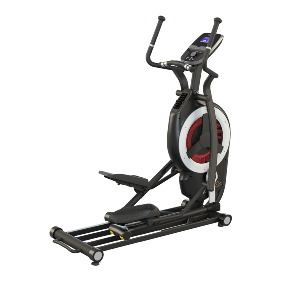
- Page 1 User's manual...
- Page 2 IE 6 8 00 / im p e t u s Testing specification : Low voltage Directive - EN60335 - 1 E&E Directive - EN62233 EMC Directive - EN55014 - 1 EN55014 - 2 EN61000 - 3 - 2 EN61000 - 3 – 3 Features of product with CE mark: Mechanical and electrical safety.
-
Page 3: Table Of Contents
IE 6 8 00 / im p e t u s INDEX Introduction/Safty Guideline..............1 2 Exploded View..................Parts List....................4-5 Assembly instruction................6-13 Monitor Instruction................14-18 Warm- up...................18-19 Cleaning & maintenance................19... -
Page 4: Introduction/Safty Guideline
IE 6 8 00 / im p e t u s INTRODUCTION / SAFETY GUIDELINE A. Introduction This user's manual contains assembly, operation, maintenance and safety information. In the interest of safety, please make certain that you read and understand all the information below. - Page 5 IE 6 8 00 / im p e t u s m. Do not “over train” Incorrect or excessive training may result in injury. n. Warning that any of the adjustment devices should not be left projecting. IMPORTANT : THE MAXIMUM RECOMMENDED WEIGHT CAPACITY FOR YOUR EQUIPMENT IS KGS.
-
Page 6: Exploded View
IE 6 8 00 / im p e t u s Exploded View... -
Page 7: Parts List
IE 6 8 00 / im p e t u s PARTS LIST NAME SPECIFICATION Q'TY NAME SPECIFICATION Q'TY Main frame Fixed foot pad Φ76.2 pipe use Fan wheel Φ450 Flat washer M5×Φ13×1.5T Tension motor Self-tap screw M5×16mm Ball bearing 6004ZZ Moving wheel Φ76... - Page 8 IE 6 8 00 / im p e t u s NAME SPECIFICATION Q'TY NAME SPECIFICATION Q'TY Hand rail ( L ) 4-20UNF 8T Ball bearing 6905ZZ Flat washer 4×2.0T×Φ28 Flat cap Φ38 Spacer sleeve Foam grip Φ31.75 pipe use 30×70 Pedal fixed assembly ( R )
-
Page 9: Assembly Instruction
IE 6 8 00 / im p e t u s Assembly instruction: Packing list Flat washer Flat washer Nylon lock nut (4X2.0X∮28) (M8X2.0TX∮20) (4X20UNF 8T E10) Philips screw Flat washer Allen bolt (M5X8mm) (M6X1.5TX∮16) Allen bolt (M8X12mm) Allen bolt (M10X65mm) Allen bolt (M6X40mm) - Page 10 IE 6 8 00 / im p e t u s Assembly: STEP 1: Attach the Main Frame (A1) to the Guide Rail Set (B1) with the 10X16L (A6) Allen Bolt and the M10X65L Allen Bolt.
- Page 11 IE 6 8 00 / im p e t u s STEP 2: Remove the ties from both Pedals (D1L) and (D1R), and place them on top of the Guide Rail Set (B1).
- Page 12 IE 6 8 00 / im p e t u s STEP 3: Firmly attach the Left Hand Rail (E1L) to the Main Frame (A1) with the 4×2.0T×Φ28 Flat Washer (E4) and the 4-20UNF 8T Nut (E10), the insert the Φ50.8 Plug (C12). Continue the same process with the Right side.
- Page 13 IE 6 8 00 / im p e t u s STEP 4: Attach the Pedal (F3) to the Pedal Fixed Assembly (F1) with the M6×Φ16×1.5T Flat Washer (F6) and the M6X40L Allen Bolt (F7). Continue the same process with the other side.
- Page 14 IE 6 8 00 / im p e t u s STEP 5: Place the Spacer Sleeve (E9) to the Left Hand Rail (E1L) and attach the Left Pedal Fixed Assembly (F1L) to the Hand Rail with the M8×Φ20×2.0T Flat Washer (D10) and M8X12L Allen Bolt (F9), then cover it with the Bushing (F10);...
- Page 15 IE 6 8 00 / im p e t u s STEP 6: Remove the M12X109L Allen Bolt (F4) and the M12 Nut (F5) from the Left Pedal Fixed Assembly (F1L), and firmly attach them to the Left Pedal Arm Assembly (D1L) .Continue the same process with the other side.
- Page 16 IE 6 8 00 / im p e t u s STEP 7: .First remove the Philip Screw (G2) from the Monitor Assembly (G1). Connect the 9-Pin female adapter with the Tension Motor (A3), and connect the 2-Pin male adapter with the Hand Pulse Wire (A31). Then attach the Monitor (G1) to the Main Frame (A1) with the Philip Screw (G2) previously removed.
-
Page 17: Monitor Instruction
IE 6 8 00 / im p e t u s MONITOR INSTRUCTION DISPLAY FUNCTION: START/STOP To start or stop workout. RESET In stop mode, press the button to back to main menu. To select training mode and adjust function value up. MODE/ENTER In stop mode, the mode is to confirm all exercise data setting, and enter into program. - Page 18 IE 6 8 00 / im p e t u s OPERATION PROCEDURE 1. Power On - Connect power supply and console will power on with a long beep sound, LCD display all segments (Drawing A) for 2 seconds and than enter into personal data setting mode Drawing A 2.
- Page 19 IE 6 8 00 / im p e t u s Drawing E Drawing D 3.1.Quick Start and Manual -- After power on, user may press START/STOP button to start exercise in MANUAL immediately without any setting. Before exercise in Manual mode, user may set up TIME, DISTANCE, CALORIES and PULSE target and press MODE button to confirm.
- Page 20 IE 6 8 00 / im p e t u s If user selects H.R.C. TAG (press the MODE button to enter), preset PULSE value “100” will be shown in flashing text and then user can press the UP and DOWN button to adjust target range from 30~230(Drawing G) Drawing F Drawing G 3.5.
-
Page 21: 11.Warm Up
IE 6 8 00 / im p e t u s Remark: 1. For SM2734-67,the console require 9V, 1.3A adaptor. 2. When user stop pedaling for 4 minutes, console will enter into power save mode, all setting and exercise data will stored until user start exercise again. -
Page 22: Cleaning & Maintenance
IE 6 8 00 / im p e t u s Quadriceps Stretch Stand on one foot with one hand hold onto the wall to balance, raise the other foot behind you, and pull up your foot as close to your buttocks as possible. Hold for 15 counts, then relax. - Page 23 Without our authorization, any contents of this manual are not allowed to be copied, saved or transferred. We reserve rights to revise specification, equipment, and maintenance information for our R&D team keeps improving our product quality. We have done the best efforts on this manual to be more comprehensible for all users.