Advertisement
5139642/01
INSTALLER AND OWNER GUIDE
Please keep me in a safe place for future use.
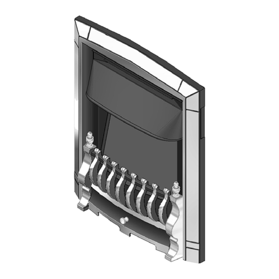
Model 850
ELECTRIC HEATER
Fitted with one of the following fascia:
Dream
Petrus.
or
(GC No. EF-032-41)
This guide is intended to help you install and care for your Valor electric heater.
Please read carefully before installing and using your heater. However, if further
information is required, our Valor Technical Helpline will be pleased to help.
Telephone 0844 8711 565 (National call rates apply in the United Kingdom).
In the Republic of Ireland Telephone 0044 844 8711 565.
Need to know your Serial
number?
You can find it on the last
page of this guide.
©
Baxi Heating U.K. Limited 2011.
Advertisement
Table of Contents

Related Manuals for Valor 850

Summary of Contents for Valor 850
- Page 1 Petrus. (GC No. EF-032-41) This guide is intended to help you install and care for your Valor electric heater. Please read carefully before installing and using your heater. However, if further information is required, our Valor Technical Helpline will be pleased to help.
- Page 2 Valor heaters are CE Approved and designed to meet the appropriate British Standards and Safety Marks. Quality and Excellence. All Valor heaters are manufactured to the highest standards of quality and excellence and are manufactured under a BS EN ISO 9001 quality system accepted by the British Standards Institute.
-
Page 3: Customer Care
This guide aims to improve your understanding and appreciation of your new Valor heater, by providing simple and informative instructions to enable you to install it and to ensure that you benefit from the excellent performance and features it has to offer. -
Page 4: Handling And Unpacking
INSTALLER AND OWNER GUIDE 2. HANDLING AND UNPACKING Before continuing any further with the installation of this heater please read the following: Important instructions. The approximate lifting weight (kg) of the heater parts are listed below: Model Heat engine Fascia Optional Spacer (See section 4) Petrus 10.0... - Page 5 The electric supply must be safely routed from the heater to an electrical socket. If the electric cable is damaged, to avoid a hazard it must be replaced by a Valor authorised service agent, or similarly qualified person (See page 23 for contact numbers).
- Page 6 4. OPTIONAL SPACER FRAME KIT An optional spacer frame kit is obtainable either from your heater supplier or direct from Valor Sales. The kit is an 80mm deep spacer kit (Kit number 0582631). This spacer enables the heater to be flat wall fixed.
- Page 7 INSTALLER AND OWNER GUIDE 6. HEATER CONTENTS Contents Qty. (Not to scale) Contents Qty. (Not to scale) ‘AAA’ Battery Heater Handset (May differ from that shown - hood not present on M4 x 25mm screw Petrus models) Washer Securing clamp Mains cable M5 x 40mm Securing clamp...
-
Page 8: Heater Dimensions
INSTALLER AND OWNER GUIDE 7. HEATER DIMENSIONS Figure 4. Dimensions (All dimensions are subject to manufacturing tolerances - shown with Dream fascia) 8. WHERE AND HOW CAN I FIT THE HEATER? Important: Before continuing with the installation of this heater please ensure that you have completed the information on the last page of this guide. - Page 9 INSTALLER AND OWNER GUIDE Do you want to fit the heater against a flat wall with the base of the heater on a hearth or similar surface? You will need to purchase the optional spacer frame kit. This spacer enables the heater to be flat wall fixed.
- Page 10 INSTALLER AND OWNER GUIDE General notes to read before fitting your heater. If fitting the heater onto a reflective or shiny surface such as a hearth we recommend that this surface does not extend further than 300mm from the fixing plane (wall).
- Page 11 INSTALLER AND OWNER GUIDE The mains cable guides. At the base of the heater you will find two electric cable guides, one each side of the heater. If required, the cable guide on the right hand side (looking from the front of the heater) can be removed and put in the rectangular slot in the centre rear of the heater.
- Page 12 INSTALLER AND OWNER GUIDE Securing the heater. The heater must be secured into position to prevent it from being tipped over. The following securing options are available: Method A - Securing the heater with Screws. Method B - Securing the heater with Wire. Method C - Securing the heater using the Optional Spacer Frame (kit number 0582631).
- Page 13 INSTALLER AND OWNER GUIDE Method B - Securing with wire. This method of securing is recommended where the wall / brickwork is in poor condition or where marble back panels / surrounds are used. Although this section deals with fireplace openings without a spacer, this method of securing the heater it can also be used with the optional spacer frame (See method C).
- Page 14 INSTALLER AND OWNER GUIDE 11. Locate the heater in the fireplace opening, then from the front of the heater, gently pull the wire on the right hand side to gather up the excess until the heater is secure. Thread the wire through the remaining small hole to lock the wire and heater in place (See item 4 - figure 11).
- Page 15 INSTALLER AND OWNER GUIDE Method D - Securing with the clamp. This method of securing cannot be used in conjunction with the optional spacer frame. This is an alternative securing method where fixing to a surround or rear wall proves impractical. 1.
- Page 16 INSTALLER AND OWNER GUIDE 9. LIGHT SHUTTER ADJUSTMENT The light shutter is an adjustable plate that increases and decreases the appearance of the flames in the flame effect. 1. Switch on the fuel effect. If you are satisfied with the appearance of the flame effect there is no need to adjust the light shutter.
-
Page 17: Fitting The Fascia
INSTALLER AND OWNER GUIDE 10. FITTING THE FASCIA Fitting the infill trim (Petrus model only). 1. Remove the infill trim from its packaging. 2. Locate the four tabs on the rear of the infill trim into the four slotted holes in the heater (See figure 18). -
Page 18: Operating The Heater
INSTALLER AND OWNER GUIDE Fitting the firefront and ash pan (Petrus model only). 1. Remove the firefront from its packaging. 2. The rear of the firefront may be fitted with hanging screws or they may be supplied in the firefront packaging. Where they are not already fitted insert them into the lower holes on both sides of the firefront. - Page 19 INSTALLER AND OWNER GUIDE Figure 24. lamp locations Pressing the ‘LAMP’ button. This turns the effect on. The indicator lamp (See figure 24) will flash green for approximately five seconds, after this time the lamp will no longer be visible. An internal fan is used to produce the flickering flame effect, room temperature air will be felt coming from the outlet at the top of the firefront.
-
Page 20: Cleaning And Maintaining The Heater
INSTALLER AND OWNER GUIDE What does the button do? Press the button once. This turns the effect on. The indicator lamp will flash green for approximately five seconds, after this time the lamp will no longer be visible. Press the button a second time. This will turn the 675 watt heater on. -
Page 21: Help And Advice
INSTALLER AND OWNER GUIDE 13. HELP AND ADVICE I have a problem with my heater! 1. My remote control does not work. The batteries in the remote control handset probably need replacing - See section 8 and figure 6. The heater can be operated manually as on pages 19 and 20. 2. -
Page 22: Warranty And Service
INSTALLER AND OWNER GUIDE Model, Name and serial number (This information can be found on a small label attached to the lower right of the heater (See figure 23) and should also have been recorded on the last page of this guide. 14. - Page 23 INSTALLER AND OWNER GUIDE You must register your heater with heateam, the service division of Baxi Heating UK Limited, either by completing and returning the registration card or calling our free telephone registration line on 0800 032 72 44. Our promise to you If you experience a fault with your new heater, we aim to provide a safe and high quality repair service supported by our dedicated national network of highly skilled engineers.
- Page 24 INSTALLER AND OWNER GUIDE Customer: Please complete the shaded areas below: Model Serial number (A label containing this information may have been placed below or can be found on the serial number label - See figure 28) A LABEL CONTAINING THE SERIAL NUMBER MAY HAVE BEEN PLACED INSIDE THIS BOX. SERIAL NUMBER LABEL TO BE AFFIXED HERE Fascia name (Block Capitals)
Need help?
Do you have a question about the 850 and is the answer not in the manual?
Questions and answers
Where can I obtain a replacement heating element for a Valor Petros 850 electric heater