Table of Contents
Advertisement
Quick Links
SERVICE MANUAL
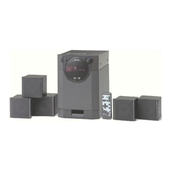
Digital Theater Station
GXW-5.1
UD
120V AC, 50Hz
SAFETY-RELATED COMPONENT
WARNING!!
COMPONENTS IDENTIFIED BY MARK
SCHEMATIC DIAGRAM AND IN THE PARTS LIST ARE
CRITICAL FOR RISK OF FIRE AND ELECTRIC SHOCK.
REPLACE THESE COMPONENTS WITH ONKYO
PARTS WHOSE PART NUMBERS APPEAR AS SHOWN
IN THIS MANUAL.
MAKE LEAKAGE-CURRENT OR RESISTANCE
MEASUREMENTS TO DETERMINE THAT EXPOSED
PARTS ARE ACCEPTABLY INSULATED FROM THE
SUPPLY CIRCUIT BEFORE RETURNING THE
APPLIANCE TO THE CUSTOMER.
ON THE
GXW-5.1
Ref. No. 3673
042001
Advertisement
Table of Contents

Related Manuals for Onkyo GXW-5.1


Summary of Contents for Onkyo GXW-5.1
- Page 1 COMPONENTS IDENTIFIED BY MARK ON THE SCHEMATIC DIAGRAM AND IN THE PARTS LIST ARE CRITICAL FOR RISK OF FIRE AND ELECTRIC SHOCK. REPLACE THESE COMPONENTS WITH ONKYO PARTS WHOSE PART NUMBERS APPEAR AS SHOWN IN THIS MANUAL. MAKE LEAKAGE-CURRENT OR RESISTANCE...
-
Page 2: Service Safety Precautions
GXW-5.1 SERVICE SAFETY PRECAUTIONS 1. Replacing the fuse 2. Safety check out This symbol located near the fuse (Only U. S. A. model) indicates that the fuse used is fast After correcting the original service problem, perform the operating type. For continued protection against fire hazard, following safety check before releasing the set to the customer. - Page 3 GXW-5.1 FL TUBE VIEW (15-BT-80GNK) (15G - 1G) –––– –––– –––– –––– –––– –––– –––– –––– –––– –––– –––– –––– –––– ––––...
- Page 4 GXW-5.1 MICROPROCESSOR CONNECTION DIAGRAM SDPSOI Q701 DSPSOO AK4112A DSPSCK 96kHz 24bit DSPCS AB/INT Q305 Q510 DSPRST Fan control Q326 Q503 TDA85630 Power IC 96FS CODECPD V load BTA17 BTA16 DIRCS ~DIRP D BTA15 ~CODECP D Not used U7001 Not used...
- Page 5 GXW-5.1 MICROPROCESSOR CONNECTION DIAGRAM SDPSOI Q701 DSPSOO AK4112A DSPSCK 96kHz 24bit DSPCS AB/INT Q305 Q510 DSPRST Fan control Q326 Q503 TDA85630 Power IC 96FS CODECPD V load BTA17 BTA16 DIRCS ~DIRP D BTA15 ~CODECP D Not used U7001 Not used...
- Page 6 GXW-5.1 MICROPROCESSOR TERMINAL DESCRIPTION Function I/O Act Description Function Description Power supply +5V 51 BTA17 Set up output terminal for BOOT ROM address. STBY/RECV Standby / received indicator output terminal. "L" : Light on 52 BTA16 Set up output terminal for BOOT ROM address.
-
Page 7: Exploded View
EXPLODED VIEW A103 A103 D901 Q905A P901 E819 A103 F901 A105 T901 E890 P7001 A101 P702 E889... -
Page 8: Exploded Parts List
GXW-5.1 EXPLODED PARTS LIST REF. NO. PART NO. DESCRIPTION (AMPLIFIER SECTION) 1A903558-1B NADG-7058-1B, DSP circuit PC board ass'y 1A903559-1B NAAF-7059-1B, Power amplifier circuit PC board ass'y 1A903560-1B NADIS-7060-1B, Display circuit PC board ass'y 1A903561-1B NAAF-7061-1B, Power supply circuit PC board ass'y... - Page 9 PRINTED CIRCUIT BOARD PARTS LIST GXW-5.1 DSP CIRCUIT PC BOARD (NADG-7058-1B) CIRCUIT NO. PART NO. DESCRIPTION CIRCUIT NO. PART NO. DESCRIPTION Sockets Q701 22241520R2 AK4112AVF P702B 25052322 or NSCT-22P2219 or Q703 22241399R2 TC7WU04F 25052516 NSCT-22P2413 Q704 22241340R9 CS492604-CL P705 25051238...
- Page 10 GXW-5.1 P o w e r a m p l i f i e r c i r c u i t P C b o a r d S C H E M A T I C D I A G R A M...
- Page 11 GXW-5.1 Q 5 0 1 TDA8563AQ J 1 B J 1 A C 5 0 1 1 0 / 5 0 C 5 0 2 1 0 / 5 0 P 5 0 1 F / L C E N T E R...
- Page 12 GXW-5.1 S C H E M A T I C D I A G R A M D S P S e c t i o n...
- Page 13 GXW-5.1...
-
Page 14: Schematic Diagram
GXW-5.1 SCHEMATIC DIAGRAM Display circuit PC board NCDIS-7060 R7020 R7021 C7001 2.2/50 D7002 Q7002 KRC104S C7017 R7009 103K J13B X7001 J13A 5MHZ Q7001 MPD78P02 MPD780204GF 5.6V ONE TIME MICON MASK MICON R7081-R7084 C7020 474J C7010 1/50 Q7004 D7009 15-BT-70GNK 5.1B... - Page 15 GXW-5.1 SCHEMATIC DIAGRAM R7061 SIG IN SIGIN FS96 96FS GXW5.1 BTA17 BAT17 BTA16 BAT16 R7020 FS96 BTA15 BAT15 R7021 AB/INT AB/INT DSPRST DSPRST DIRPD DIRPD CODECPD CODECPD DSPCS DSPCS 5.6V DIRCS DIRCS C7001 DSPSCK DSPSCK 2.2/50 DSPSDO DSPSDO D7002 DSPSDI...
-
Page 16: Block Diagram
GXW-5.1 BLOCK DIAGRAM DSP circuit PC board Power amplifier circuit PC board NAAF-7059 NADG-7058 Q805 Q301 NJM4565M-D Q503 Q304 Q316 TC9482N TDA8563Q P503 NJM4565M-D NJM4565M-D 560Hz MUTING Q312,Q314 56KHz MUTING Q804 Q803 +Lch Q311 NJM4565M-D Q806 Q801 P7201 NJM4565M-D NJM4565M-D... -
Page 17: Packing Parts List
PACKING PARTS LIST GXW-5.1 REF. NO. PART NO. DESCRIPTION 29343033 Instruction manual 2050070 NOP-1P150, Fiber cable ass'y 24140442 RC-442S, Remote controller 3010054 UM-3, Battery 29362893 Label, serial number 180-000044 Speaker cord ass'y, L=2.5m 180-000229 Speaker cord ass'y,L=8m 404-NS-290 Pad, 3peace/1set... - Page 18 GXW-5.1 ONKYO CORPORATION Sales & Product Planning Div. : 2-1, Nisshin-cho, Neyagawa-shi, OSAKA 572-8540, JAPAN Tel: 072-831-8111 Fax: 072-833-5222 ONKYO U.S.A. CORPORATION 18 Park Way, Upper Saddle River, N.J. 07458, U.S.A. Tel: 201-785-2600 Fax: 201-785-2650 E-mail: onkyo@onkyousa.com HOMEPAGE http://www.onkyo.co.jp/...
- Page 19 GXW-5.1 PRINTED CIRCUIT BOARD PARTS LIST CIRCUIT NO. PART NO. DESCRIPTION CIRCUIT NO. PART NO. DESCRIPTION Coils Fuse holders L7001-L7003 231237K220R2 NCH-1477, Choke F901A,F901B ! 25052133 NSCT-1P2031 Capacitors Terminals C301,C302-C307, 354781009 10uF,50V, Elect. P501 25060305 NTM-6PDML236 C305-C312 P502 25060306 NTM-4PDML237...
- Page 20 PRINTED CIRCUIT BOARD PARTS LIST GXW-5.1 CIRCUIT NO. PART NO. DESCRIPTION POWER SWITCH PC BOARD (NASW-7121-1B) Remote sensors CIRCUIT NO. PART NO. DESCRIPTION U7001 241305 or GP1U281X or Switch 241332 PIC-28143TE5 S901 ! 25065620 NRC-11007P, Power FL tube Capacitor Q7004...
Need help?
Do you have a question about the GXW-5.1 and is the answer not in the manual?
Questions and answers