Table of Contents
Advertisement
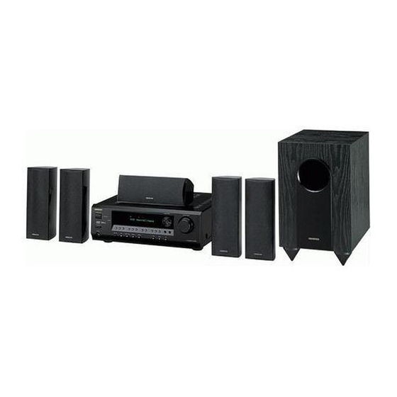
5.1ch Home Theater System
HT-S3100
HT-S3105
AV Receiver (HT-R340)
Speaker Package
HTP-360
(North American and Asian models)
HTP-318
(European models)
Instruction Manual
Thank you for purchasing an Onkyo 5.1ch Home
Theater System. Please read this manual thoroughly
before making connections and plugging in the unit.
Following the instructions in this manual will enable
you to obtain optimum performance and listening
enjoyment from your new 5.1ch Home Theater Sys-
tem.
Please retain this manual for future reference.
Contents
Introduction ..................................... 2
Connection .................................... 20
Turning On & First Time Setup..... 37
Basic Operation
Playing your AV components ....... 39
Using the Tuner............................ 41
Enjoying the Listening Modes ..... 49
Advanced Operation ..................... 51
Troubleshooting ............................ 58
Specifications................................ 62
E
n
Advertisement
Table of Contents

Subscribe to Our Youtube Channel
Related Manuals for Onkyo S3100


Summary of Contents for Onkyo S3100
- Page 1 Using the Tuner......41 Instruction Manual Enjoying the Listening Modes ..49 Thank you for purchasing an Onkyo 5.1ch Home Theater System. Please read this manual thoroughly before making connections and plugging in the unit. Following the instructions in this manual will enable you to obtain optimum performance and listening enjoyment from your new 5.1ch Home Theater Sys-...
-
Page 2: Important Safety Instructions
WARNING: AVIS WARNING TO REDUCE THE RISK OF FIRE OR ELECTRIC RISK OF ELECTRIC SHOCK RISQUE DE CHOC ELECTRIQUE DO NOT OPEN NE PAS OUVRIR SHOCK, DO NOT EXPOSE THIS APPARATUS TO RAIN OR MOISTURE. The lightning flash with arrowhead symbol, within an equilateral triangle, is intended to alert the user to the CAUTION: presence of uninsulated “dangerous voltage”... -
Page 3: Precautions
MATCH WIDE BLADE OF PLUG TO WIDE SLOT, are wet or damp. If water or any other liquid gets FULLY INSERT. inside this unit, have it checked by your Onkyo dealer. Modèle pour les Canadien 6. Handling Notes REMARQUE: CET APPAREIL NUMÉRIQUE DE... -
Page 4: Speaker Precautions
GERMANY that’s too close to your TV or monitor. declare in own responsibility, that the ONKYO product Do not place SKM-360S/SKM-318S close to TV or a described in this instruction manual is in compliance with the... -
Page 5: Features
*2. “DTS” and “Neo:6” are trademarks of Digital Theater Sys- • Color-coded speaker terminals and speaker cable tems, Inc. *3. OptiResponse, and OR-EQ are trademarks of Onkyo Cor- poration. *4. Apple and iPod are trademarks of Apple Computer, Inc., registered in the U.S. and other countries. -
Page 6: Table Of Contents
Contents Package Contents Make sure you have the following items: Introduction Important Safety Instructions ....2 AV Receiver HT-R340 Precautions ..........3 Speaker Precautions ......4 Features ........... 5 Package Contents ........6 Front & Rear Panels........ 8 Speaker Package ........11 Remote Controller......... - Page 7 Package Contents—Continued Speaker Package HTP-360 Speaker Package Accessories (North American and Asian models) (Red) (White) (Green) Front speakers (SKF-360F L/R) Speaker cable for front speakers and center speaker 11 ft. (3.5 m) Center speaker (SKC-360C) (Blue) (Gray) Speaker cables for surround speakers 30 ft. (9 m) Surround speakers (Purple) (SKM-360S L/R)
-
Page 8: Front Panel
Front & Rear Panels Front Panel North American and Asian Models 7 8 9 J K TUNING / PRESET MASTER VOLUME STANDBY/ON ENTER STANDBY RETURN SETUP A SPEAKERS B TONE STEREO LISTENING MODE DISPLAY DIGITAL INPUT DIMMER MEMORY TUNING MODE CLEAR PHONES MULTl CH... - Page 9 Front & Rear Panels—Continued MEMORY button (42) PHONES jack (45) This button is used when storing or deleting radio This 1/4-inch phone jack is for connecting a stan- presets. dard pair of stereo headphones for private listening. TUNING MODE button (41) SPEAKERS A &...
-
Page 10: Rear Panel
Note: COMPONENT VIDEO can only be used with Onkyo components. A DVD player, TV, or other component that sup- CD IN ports component video can be connected here. These analog inputs can be used to connect a CD AM ANTENNA player with analog outputs. -
Page 11: Speaker Package
Speaker Package Front, Center, Surround, & Subwoofer speakers (SKF-360F/SKF-318F, SKC-360C/SKC-318C, SKM-360S/SKM-318S, SKW-360/SKW-318) ■ Rear SKF-360F/SKM-360S SKF-318F/SKM-318S SKW-360/SKW-318 SKC-360C/SKC-318C Speaker terminals Speaker mount/bracket inserts These push terminals are for connecting the speaker These threaded inserts can be used to attach the to the HT-R340 with the supplied speaker cables. -
Page 12: Remote Controller
AV receiver and an Onkyo cassette TAPE TAPE INPUT SELECTOR recorder connected via ■ DVD, CD, MD, CDR & HDD Modes With these modes, you can control an Onkyo MULTI CH DVD player and CD/MD/CDR/HDD player/recorder. TAPE TUNER + 10... - Page 13 Remote Controller—Continued For detailed information, see the pages in parentheses. MUTING button (46) This button is used to mute the AV receiver. ON/STANDBY button (37) SETUP button (51, 53–56) This button is used to set the AV receiver to On or This button is used to access various settings.
-
Page 14: Dvd Mode
Remote Controller—Continued ON/STANDBY button DVD Mode This button sets the DVD player to On or Standby. Number buttons To select your DVD player as the input source, press: These buttons are used to enter title, chapter, and track numbers and to enter times for locating spe- RECEIVER cific points in time. - Page 15 Remote Controller—Continued ON/STANDBY button CD Mode This button sets the CD player to On or Standby. Number buttons To select your CD player as the input source, press: These buttons are used to enter track numbers and to enter times for locating specific points in time. RECEIVER DISC +/–...
- Page 16 Remote Controller—Continued ON/STANDBY button MD, & CDR Mode This button sets the MD/CD recorder to On or Standby. To select your MiniDisc or CD recorder as the input Number buttons source, press: These buttons are used to enter track numbers and to enter times for locating specific points in time.
- Page 17 ON/STANDBY button HDD Mode This button sets the iPod to On or Standby. HDD mode is for controlling an Apple iPod in an Onkyo ALBUM +/– button RI Dock that’s connected via This button selects the next or previous album on an iPod.
- Page 18 ] button is used to start rewind. The FF [ ] button is used to start fast forward. TAPE mode is used to control an Onkyo cassette recorder connected to the AV receiver via To set the remote controller to TAPE mode, press the [RECEIVER] REMOTE MODE button.
-
Page 19: Before Using The Av Receiver
Before Using the AV receiver Notes: Setting the Voltage Selector • If the remote controller doesn’t work reliably, try (on some models) replacing the batteries. Some models have a voltage selector switch for compat- • Don’t mix new and old batteries or different types of ibility with power systems around the world. -
Page 20: Enjoying Home Theater
Enjoying Home Theater Speaker Sets A and B You can use two sets of speakers with the AV receiver: speaker set A and speaker set B. Speaker set A should be used in your main listening room for up to 5.1-channel playback. *While speaker set B is on, speaker set A is reduced to 2.1-channel playback. -
Page 21: Connecting Your Speakers
Connecting Your Speakers Speaker Connection Precautions Connecting Speaker Read the following before connecting your speakers: The AV receiver’s positive (+) speaker terminals are color-coded for ease of identification. (The negative (–) • You can connect speakers with an impedance of speaker terminals are all black.) 6 ohms or higher. -
Page 22: Wall Mounting
Connecting Your Speakers—Continued Use screws with a head diameter of 5/16" (9 mm) or less Wall Mounting and a shank diameter of 1/8" (4 mm) or less. With hollow The speakers can easily be wall mounted by using the walls, use a cable/pipe detector to check for any power keyhole slots. -
Page 23: Using The Rubber Stoppers For A More Stable Platform
Connecting Your Speakers—Continued Using the Rubber Stoppers for a More Stable Platform We recommend using the provided rubber stoppers to achieve the best possible sound from your speakers. The rubber stoppers prevent the speakers from moving, pro- viding a more stable platform. Use thick stoppers for the center speaker, and thin stoppers for the other speakers. -
Page 24: Connecting Antenna
Connecting Antenna This section explains how to connect the supplied indoor Connecting the AM Loop Antenna FM antenna and AM loop antenna, and how to connect commercially available outdoor FM and AM antennas. The supplied indoor AM loop antenna is for indoor use only. -
Page 25: Connecting An Outdoor Fm Antenna
Connecting Antenna—Continued Connecting an Outdoor FM Antenna Connecting an Outdoor AM Antenna If you cannot achieve good reception with the supplied If good reception cannot be achieved using the supplied indoor FM antenna, try a commercially available out- AM loop antenna, an outdoor AM antenna can be used in door FM antenna instead. -
Page 26: Connecting Your Components
Connecting Your Components AV Connection Color Coding About AV Connections RCA-type AV connections are usually color coded: red, • Before making any AV connections, read the manuals white, and yellow. Use red plugs to connect right-chan- supplied with your other AV components. nel audio inputs and outputs (typically labeled “R”). -
Page 27: Which Connections Should I Use
Connecting Your Components—Continued Connecting Both Audio & Video By connecting both the audio and video outputs of your DVD player and other AV components to the AV receiver, you can select both the audio and video simultaneously simply by selecting the appropriate input source on the AV receiver. : Signal Flow Video Video... -
Page 28: Connecting A Dvd Player
Connecting Your Components—Continued Connecting a DVD Player Step 1: Video Connection (DVD Player to AV Receiver to TV) If your TV has component video input jacks, connect your DVD player to the AV receiver’s COMPONENT VIDEO DVD IN jacks. And connect the AV receiver’s COMPONENT VIDEO OUT jacks to your TV. This will provide better picture quality than connection If your TV doesn’t have component video input jacks, connect your DVD player to the AV receiver’s DVD IN VIDEO jack. - Page 29 Connecting Your Components—Continued Step 2: Audio Connection If your DVD player has a coaxial digital audio output jack, connect it to the AV receiver’s DIGITAL IN COAX- IAL jack. You can enjoy Dolby and DTS listening modes with this connection. If your DVD player has an optical digital audio output jack instead of coaxial one, connect it to the AV receiver’s DIGITAL IN OPTICAL 1 or 2 jack, and set the DIGITAL INPUT assignment to OPT1 or OPT 2 (see page 38).
-
Page 30: Connecting A Vcr
Connecting Your Components—Continued Connecting a VCR Connecting a VCR for Playback Step 1: Video Connection (VCR to AV Receiver to TV) Connect your VCR’s video output jack to the AV receiver’s VIDEO 1 IN jack and connect the AV receiver’s MONITOR OUT jack to your TV’s video input jack. - Page 31 Connecting Your Components—Continued Connecting a VCR for Recording Step 1: Video Connection Connect the AV receiver’s VIDEO 1 OUT jack to your VCR’s video input jack. Step 2: Audio Connection Connect the AV receiver’s VIDEO 1 OUT L/R jacks to your VCR’s audio input jacks. HT-R340 : Signal Flow VIDEO...
-
Page 32: Connecting A Satellite, Cable, Set-Top Box, Or Other Video Source
Connecting Your Components—Continued Connecting a Satellite, Cable, Set-top Box, or Other Video Source Step 1: Video Connection Connect your set-top box’s video output jack to the AV receiver’s VIDEO 2 IN jack and connect the AV receiver’s MONITOR OUT jack to your TV’s video input jack. If your VCR and TV have component video jacks, connect your set-top box’s component video output to the AV receiver’s COMPONENT VIDEO VIDEO 2 IN jacks, and connect the AV receiver’s COMPONENT VIDEO OUT jacks to your TV’s component video in jacks. -
Page 33: Connecting A Cd Player Or Turntable
Connecting Your Components—Continued Connecting a CD Player or Turntable ■ CD Player or Turntable with Built-in Phono Preamp Connect your CD player’s analog audio output jacks, or your turntable with built-in phono preamp’s audio output jacks to the AV receiver’s CD IN L/R jacks. With connection , you can listen to and record audio from the CD player or turntable. - Page 34 TAPE IN jacks are especially designed for use with the RI Dock. Notes: • If you have an Onkyo DS-A1 RI Dock, connect its S-VIDEO jack directly to an S-Video input on your TV. • Set the RI Dock’s RI MODE switch to HDD or HDD/DOCK.
-
Page 35: Connecting A Cassette, Cdr, Minidisc, Or Dat Recorder
Connecting Your Components—Continued Connecting a Cassette, CDR, MiniDisc, or DAT Recorder Connect your recorder’s audio input jacks to the AV receiver’s TAPE OUT L/R jacks, and connect your recorder’s audio output jacks to the AV receiver’s TAPE IN L/R jacks. With connection , you can play and record with the recorder. -
Page 36: Connecting The Power Cord
Connecting Your Components—Continued Connecting Onkyo Components Step 1: Make sure that each Onkyo component is connected to the AV receiver with an analog audio cable. Step 2: Make the connection. Step 3: If you’re using an MD, CDR, or HDD component, change the Input Display (see page 38). -
Page 37: Turning On The Av Receiver
If you have, see “Assigning Digital Inputs to Input Sources” on page 38. COAXIAL OPTICAL ■ Have you connected an Onkyo MD recorder, CD recorder, or RI Dock? If you have, see “Changing the Input Display” on page 38. CD recorder, MD recorder... -
Page 38: First Time Setup
First Time Setup Assigning Digital Inputs to Input Changing the Input Display Sources If you connect an -capable Onkyo MiniDisc recorder, CD recorder, or RI Dock to the TAPE IN/OUT 2, 3 or VIDEO 3 IN jacks, for to work properly, you must change this setting. -
Page 39: Basic Av Receiver Operation
Playing Your AV Components Basic AV Receiver Operation ON/STANDBY REMOTE MODE DISPLAY RECEIVER TAPE INPUT SELECTOR TUNING / PRESET MASTER VOLUME STANDBY/ON ENTER MULTI CH STANDBY RETURN SETUP TAPE TUNER A SPEAKERS B TONE STEREO LISTENING MODE DISPLAY DIGITAL INPUT RT/PTY/TP MEMORY TUNING MODE CLEAR + 10... - Page 40 Playing Your AV Components—Continued You can display various information about the current Using the Multichannel Input input source as follows. Press the [RECEIVER] button, RECEIVER and then press the [DISPLAY] ON/STANDBY REMOTE MODE RECEIVER RECEIVER button repeatedly to cycle TAPE INPUT SELECTOR through the available informa- tion.
-
Page 41: Using The Tuner
Using the Tuner Listening to the Radio Tuning into Radio Stations ■ Auto Tuning Mode TUNING MODE TUNING Press the [TUNING MODE] button TUNING MODE so that the AUTO indicator TUNING / PRESET MASTER VOLUME appears on the display. STANDBY/ON ENTER STANDBY RETURN... - Page 42 Using the Tuner—Continued Presetting Radio Stations Deleting Presets 2, 4 TUNING / PRESET MASTER VOLUME TUNING / PRESET MASTER VOLUME STANDBY/ON STANDBY/ON ENTER ENTER STANDBY STANDBY A SPEAKERS B RETURN SETUP RETURN SETUP TONE STEREO LISTENING MODE DISPLAY DIGITAL INPUT RT/PTY/TP MEMORY TUNING MODE A SPEAKERS B TONE...
- Page 43 Using the Tuner—Continued Using RDS (European models only) Program Types Used in Europe (PTY) RDS only works with European models and only in areas Type Display Description where RDS broadcasts are available. When tuned into an None NONE No program type. RDS station, the RDS indicator appears.
- Page 44 Using the Tuner—Continued Displaying Radio Text (RT) To start the search, press [ENTER]. ENTER The AV receiver searches until it finds a station of the type you specified, at TUNING / PRESET which point it stops briefly before con- MASTER VOLUME STANDBY/ON tinuing with the search.
-
Page 45: Common Functions
Common Functions This chapter explains functions that can be used with any input source. Press TONE, –, + ON/STANDBY REMOTE MODE RECEIVER [RECEIVER] TAPE INPUT SELECTOR first TUNING / PRESET MASTER VOLUME STANDBY/ON ENTER STANDBY RETURN SETUP A SPEAKERS B TONE STEREO LISTENING MODE... -
Page 46: Using The Sleep Timer
Common Functions—Continued Using the Sleep Timer ON/STANDBY Press REMOTE MODE With the sleep timer, you can set the AV receiver so that RECEIVER [RECEIVER] it automatically turns off after a set period. TAPE first INPUT SELECTOR Remote Press the remote controller’s controller [SLEEP] button repeatedly to select the required sleep time. -
Page 47: Adjusting Speaker Levels
Common Functions—Continued Adjusting Speaker Levels ON/STANDBY Press You can adjust the level of each speaker in speaker set A REMOTE MODE RECEIVER [RECEIVER] while listening to an input source. These temporary TAPE first INPUT SELECTOR adjustments are cancelled when the AV receiver is set to Standby. -
Page 48: Recording
Recording This chapter explains how to record the selected input Recording from Different AV Sources source to an AV component with recording capability, and how to record audio and video from two different With this function, you can record audio and video from sources. -
Page 49: Using The Listening Modes
✔ Multich PLII Movie/Music/Game ✔ ✔ ✔ Neo:6 Cinema Neo:6 Music ✔ ✔ Dolby D ✔ ✔ Mono Movie Orchestra Onkyo Unplugged ✔ ✔ ✔ ✔ ✔ ✔ ✔ ✔ Original Studio-Mix TV Logic All Ch Stereo Full Mono *1. In the Direct listening modes, PCM signals at 32 kHz, 44.1 kHz, and 48 kHz are processed at 64 kHz, 88.2 kHz, and 96 kHz respectively. -
Page 50: About The Listening Modes
The selected input source is output directly with minimal processing for a pure sound. Stereo The selected input source is processed as a stereo signal Onkyo Original DSP Modes and output by the front left and right speakers and the subwoofer. Mono Movie... -
Page 51: Adjusting The Listening Modes
Adjusting the Listening Modes Use the Up and Down [ ]/[ ] buttons to select “4. Audio ON/STANDBY REMOTE MODE Adjust,” and then press the RECEIVER RECEIVER TAPE [ENTER] button. INPUT SELECTOR MULTI CH TAPE TUNER ENTER + 10 --/--- DIMMER SLEEP DISC... -
Page 52: Using The Late Night Function
Adjusting the Listening Modes—Continued PLII Music Mode Settings Using the Late Night Function (Dolby Digital only) These settings apply to only 2-channel (stereo) sources. ■ Panorama With the Late Night function, you can reduce the With this function, you can broaden the width of the dynamic range of Dolby Digital material so that you can still hear quiet parts even when listening at low volume front stereo image when using the Pro Logic II Music... -
Page 53: Advanced Setup
Advanced Setup Advanced Speaker Settings Use the Up and Down [ buttons to select “2. SP Dis- tance,” and then press the [ENTER] button. ON/STANDBY REMOTE MODE RECEIVER RECEIVER TAPE INPUT SELECTOR ENTER MULTI CH TAPE TUNER + 10 While “Unit” is displayed, use the --/--- DIMMER SLEEP... -
Page 54: Speaker Levels
Advanced Setup—Continued Speaker Levels Repeat step 4 so that the level of the test tone from each speaker With this function, you can adjust the volume of each is the same. speaker so that all speakers can be heard equally at the listening position. - Page 55 Advanced Setup—Continued Use the Down [ ] button to Speaker Configuration, Crossover Frequency, select “Front,” and then use the and Double Bass settings only need to be Left and Right [ ] buttons to changed if you’re not using the speakers in select Small or Large.
- Page 56 Advanced Setup—Continued Crossover Frequency Use the Down [ ] button to select “Double Bass,” and then This setting only applies to the speakers that you speci- fied as Small in the “Speaker Configuration” on page 55. use the Left and Right [ buttons to select: To get the best bass performance from your speaker sys- tem, you need to set the crossover frequency according...
-
Page 57: Digital Input Signal Formats
Advanced Setup—Continued Digital Input Signal Formats Correcting Sound and Picture Sync The following table shows the display indicators for each When using progressive scanning on your DVD player, supported digital signal format. you may find that the picture and sound are out of sync. With this setting, you can correct this by delaying the Format Display... -
Page 58: Troubleshooting
If you can’t resolve the issue yourself, try resetting • If the MUTING indicator is shown on the display, the AV receiver before contacting your Onkyo dealer. press the remote controller’s [MUTING] button to To reset the AV receiver to its factory defaults, unmute the AV receiver (page 46). - Page 59 Troubleshooting—Continued The subwoofer produces no sound? any sound, in which case you should stop your player • The subwoofer outputs no sound while only speaker for about three seconds, and then resume playback. set B is on. Turn on speaker set A. •...
- Page 60 Input Display to MD, CDR, or HDD (see Recording page 38). • To control an Onkyo component that’s connected via Can’t record? , point the remote controller at the AV receiver. • On your recorder, make sure the correct input is selected.
- Page 61 five seconds, and then plug it back in again. Onkyo is not responsible for damages (such as CD rental fees) due to unsuccessful recordings caused by the unit’s malfunction. Before you record important data, make sure that the material will be recorded cor- rectly.
-
Page 62: Specifications
Specifications Amplifier Section General Rated Output Power Power Supply North American: AC 120 V, 60 Hz North American (FTC): Australian and European: AC 230-240 V, 50 Hz (FL, FR, C, SL, SR) 100 watts minimum continuous power per channel, 8 ohm loads, at 1 kHz, with Others: AC 120/220–240 V, 50/60 Hz a maximum total harmonic distortion AC 220–230 V, 50/60 Hz... - Page 63 Specifications—Continued 5.1ch Home Theater Speaker Package ■ Passive Subwoofer (SKW-360/SKW-318) ■ Center Speaker (SKC-360C/SKC-318C) Type: Bass-reflex type Passive subwoofer Type: 2 Way Bass-reflex 6 Ω 6 Ω Impedance: Impedance: Maximum input power: 130 W Maximum input power: 120 W Output sound pressure Output sound pressure level: 83 dB/m/w...
- Page 64 Unit 1&12, 9/F, Ever Gain PlazaTower 1, 88, Container Port Road, Kwai Chung, N.T., HONG KONG Tel: 852-2429-3118 Fax: 852-2428-9039 http://www.ch.onkyo.com/ I0801-1 SN 29344695 (C) Copyright 2008 ONKYO CORPORATION Japan. All rights reserved. * 2 9 3 4 4 6 9 5 *...
Need help?
Do you have a question about the S3100 and is the answer not in the manual?
Questions and answers