Table of Contents
Advertisement
Quick Links
Service Manual
Apollo GX Series
Confidential, unpublished property of Garmin AT, Inc. Use and distribution is limited
solely to authorized personnel. The use, disclosure, reproduction, modification, transfer,
or transmittal of any portion of this work for any purpose in any form or by any means
without the express written permission of Garmin AT is strictly prohibited.
October 2004
560-7001-501 Rev. --
Advertisement
Table of Contents

Related Manuals for Garmin APOLLO GX SERIES


Summary of Contents for Garmin APOLLO GX SERIES
- Page 1 Service Manual Apollo GX Series Confidential, unpublished property of Garmin AT, Inc. Use and distribution is limited solely to authorized personnel. The use, disclosure, reproduction, modification, transfer, or transmittal of any portion of this work for any purpose in any form or by any means without the express written permission of Garmin AT is strictly prohibited.
- Page 2 Information in this document is subject to change without notice. Garmin reserves the right to change or improve their products and to make changes in the content of this material without obligation to notify any person or organization of such changes or improvements.
- Page 3 Navigating Our Phone System When you call Garmin AT, the first thing you hear is, “Thank you for calling Garmin AT. Our business hours are…” This is followed by a series of menu choices to help get you to the appropriate department.
-
Page 4: Table Of Contents
ETURN TO ERVICE ROCEDURE ..........................7-25 ROCEDURES ..........................7-55 INAL HECKOUT 8. R ....................... 8-1 HAPTER EPLACEMENT ROCEDURES ................................8-1 URPOSE ............................8-1 RELIMINARY ............................8-1 OARD OCATIONS ........................8-4 HASSIS OVER EPLACEMENT GX Service Manual © 2004 Garmin AT... - Page 5 ..............................11-2 ARTS GX55 P ..............................11-2 ARTS GX60 P ..............................11-3 ARTS GX65 P ..............................11-4 ARTS ..............................11-5 ARDS ..........................11-5 AINTENANCE UPPLIES 12. R ...................... 12-1 HAPTER EGULATORY OCUMENTS 13. S ......................13-1 HAPTER ERVICE HEET © 2004 Garmin AT GX Service Manual...
- Page 6 ............. 10-17 IGURE OWER UPPLY UDIO LOCK IAGRAM 9-13. GX55 A ) (S 2).............. 10-18 IGURE SSEMBLY EFERENCE HEET 9-14. GX50, 60, 65 A ) (S 2) ..........10-20 IGURE SSEMBLY EFERENCE HEET GX Service Manual © 2004 Garmin AT...
-
Page 7: History Of Revisions
This revision incorporates changes in drawings due to previous ENs. Refer to EN6010, EN6125, EN6320, EN6393, and EN6432. October 2004 ...........................Revision -- Changed UPSAT to Garmin AT. Also deleted three chapters to make more web friendly. © 2004 Garmin AT... - Page 8 Garmin AT Rev. -- This Page Intentionally Left Blank viii GX Service Manual © 2004 Garmin AT...
-
Page 9: Chapter 1. Service Requirements Preliminary Data
See the parts list for these items. Reference the following standards: IPC-R-7721 and 7711 (or newer) Guidelines for Rework and Repair of Printed Boards and Assemblies. IPC-A-610A (or newer) Acceptability of Electronic Assemblies. © 2004 Garmin AT GX Service Manual... -
Page 10: Sources For Solderings
2. Exterior and interior screws should be tightened only with a torque screwdriver set to the specified torque. Refer to the instruction manual supplied with the torque screwdriver. The correct tightening torque is shown in each procedure. GX Service Manual © 2004 Garmin AT... -
Page 11: Guide For Using Fasteners
1. Make sure that you use the proper screw in each location. Note the difference between countersunk and undercut screws. Use appropriate screws. 2. Be careful not to damage screws. Screws with damaged threads or stripped heads must be discarded and replaced with the appropriate screws. © 2004 Garmin AT GX Service Manual... - Page 12 Garmin AT Rev -- GX Service Manual © 2004 Garmin AT...
-
Page 13: Chapter 2. Introduction
Flybuddy GPS receivers. The GX55 connectors and antenna footprint are the same as the Apollo Loran and Flybuddy GPS receivers. The GX55 is TSO-C129 Class A2 authorized for IFR en route and terminal operation. © 2004 Garmin AT GX Service Manual... -
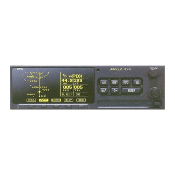
Page 14: Display
The dual concentric knobs on the right side of the front panel are used to select pages, edit characters and values, or other options. The large knob moves the cursor and the small knob changes characters. Either may change pages depending on the function. GX Service Manual © 2004 Garmin AT... -
Page 15: Keys
MAP function. You can always press the NAV key to go back to the navigation function and view the normal “smart” keys. © 2004 Garmin AT GX Service Manual... -
Page 16: Map Function Smart Keys
When the SCAN key is active (highlighted) in the moving map display, turning the large knob will move between the nearest airports. You can then press INFO to view information about that airport. GX Service Manual © 2004 Garmin AT... - Page 17 Press the XIT key to return to the start- up sequence, or wait for test completion. The XIT key will disappear when testing is complete. © 2004 Garmin AT GX Service Manual...
-
Page 18: Apollo Gx Features
5 nm ATC rings around airports with control towers − Airspaces displayed by sector or outer boundary − Airspace display controllable by type − Approach preview page (GX50/60 only) − Route line displayed GX Service Manual © 2004 Garmin AT... - Page 19 25 sec. (typical) with current almanac, position, time, and ephemeris • 55 seconds typical with current almanac, position, & time • Reacquisition: 2.5 seconds typical • Position update interval: 1 second typical • Datum: WGS-84 © 2004 Garmin AT GX Service Manual...
- Page 20 VDI superflag 400 mA source • Annunciators − MSG (message) − PTK (parallel track) − OBS/HLD (waypoint sequencing hold) GX50/60 only − APPRCH (approach enabled) GX50/ 60 only − ACTIVE (approach active) GX50/60 only GX Service Manual © 2004 Garmin AT...
- Page 21 -55º C to +85º C • Temperature variation 2º C per minute • Humidity 95% at 50º C for 6 hrs (2 day cycle) • Maximum altitude 55,000 feet • Cooling Not required © 2004 Garmin AT GX Service Manual...
- Page 22 Distortion - <5% at rated output at 1000 Hz • AGC characteristics − <3 dB variation in audio output from 5 to 100 mV input − 15% to 90% modulation • Squelch control - automatic with manual override 2-10 GX Service Manual © 2004 Garmin AT...
- Page 23 − TSO C128 − TSO C37d − TSO C38d • GX65 − TSO C129A A2 − TSO C128 − TSO C37d − TSO C38d Features and specifications subject to change without notice. © 2004 Garmin AT GX Service Manual 2-11...
- Page 24 Garmin AT Rev -- 2-12 GX Service Manual © 2004 Garmin AT...
-
Page 25: Chapter 3. Installationm
Chapter 3. Installation Manuals Please refer to the Dealer’s Only website at http://www.garmin.com to download the latest installation manuals. © 2004 Garmin AT GX Service Manual... - Page 26 Garmin AT Rev -- GX Service Manual © 2004 Garmin AT...
-
Page 27: Chapter 4. Antenna Installation
Chapter 4. Antenna Installation Guides © 2004 Garmin AT GX Service Manual... - Page 28 Garmin AT Rev -- GX Service Manual © 2004 Garmin AT...
-
Page 29: Chapter 5. Aircraft Installation
GPS antenna. Check the interference levels at different top- mounted locations using the portable GPS antenna. If the interference is too strong, causing a loss of GPS signals in all possible antenna locations, follow the suppression guidelines below. You should © 2004 Garmin AT GX Service Manual... - Page 30 We have also seen some extreme cases where the interference emits from the front panel and display area of the GPS receiver. Re-positioning the antenna can usually correct the problem. If not contact the manufacturer of the GPS receiver for additional help. It’s GX Service Manual © 2004 Garmin AT...
- Page 31 GPS notch filters are installed. Test one more time. If the interference has been eliminated, permanently mount the GPS antenna and re-test. These guidelines can be used to minimize GPS interference problems. © 2004 Garmin AT GX Service Manual...
- Page 32 Garmin AT Rev -- GX Service Manual © 2004 Garmin AT...
-
Page 33: Chapter 6. Theory Of Operation
Asynchronous Serial I/O (SIO) • Direct Memory Access (DMA) controller • System Management Mode (SMM) • Clock and power management unit • Synchronous Serial I/O (SSIO) • Chip-select Unit (CSU) • Refresh Control Unit (RCU) © 2004 Garmin AT GX Service Manual... - Page 34 When using both SRAM devices, they are connected to allow word access. The BLE and BHE connections allow for aligned and non-aligned word access as well as byte access. GX Service Manual © 2004 Garmin AT...
- Page 35 Altitude Input The GX50/60/65 includes an altitude input, which is used for GPS RAIM calculations as well as providing for altitude assist functions such as altitude preset and hold and 3D airspace alerts. The © 2004 Garmin AT GX Service Manual...
-
Page 36: Power Supply
The NAV board power supply provides +12.5 VDC to the display assembly DC-DC converter (P202 Pin 1) and +5 VDC to the display assembly digital logic (P202 pin 5). Service and troubleshooting of the display assembly are limited to whole unit replacement. GX Service Manual © 2004 Garmin AT... -
Page 37: Comm Theory Of Operation
Comm module requires a microphone input of 100 mV RMS for full (90%) modulation. The audio frequency response of the modulation signal varies <3 dB from 350 Hz to 2500 Hz, is >3 dB down at 220 and 3000 Hz, and 18 dB down at 4000 Hz. © 2004 Garmin AT GX Service Manual... - Page 38 Garmin AT Rev -- Frequency Stability The transmit frequency is controlled by a frequency synthesizer. The synthesizer provides for a transmit frequency tolerance within 15 ppm (required spec is 30 ppm). GX Service Manual © 2004 Garmin AT...
-
Page 39: Chapter 7. Return To Service
RF connector that has a quick bayonet mount bandpass filter Celsius (temperature) calibration Course Deviation Indicator Coax coaxial cable COMM, or Comm communication CONFIG configuration digital to analog converter decibel (a logarithmic expression of ratios) © 2004 Garmin AT GX Service Manual... - Page 40 (millions of cycles per second) microphone monitor message millivolt navigation oscillator peak Parts Per Million PREV previous parallel track Push To Talk power resistance (measured in ohms) reference Radio Frequency GX Service Manual © 2004 Garmin AT...
- Page 41 Vcesat saturation voltage between a transistor’s collector and emitter Volts Direct Current Vertical Deviation Indicator version Visual Flight Rules voice operated relay VSWR voltage standing wave ratio watts WPT(S) waypoint(s) µV microvolts Ω © 2004 Garmin AT GX Service Manual...
-
Page 42: Preliminary Data
Circuit boards or components must only be carried in a nonconductive, anti-static bag. Reference EIA Standard # EIA- 625. GX Service Manual © 2004 Garmin AT... - Page 43 Spectrum Analyzer Noise Level (<50 kHz spans) -114 dBm Spectrum Analyzer Level +/-2.5 dB SINAD (0 to 46 dB SINAD) +/-1 dB Distortion Measurement +/-1 dB All test equipment must be current on calibrations before performing these tests. © 2004 Garmin AT GX Service Manual...
- Page 44 Note: Placing a jumper between pins 7 and 8 of J2 on the NAV board, and then turning the unit on may also access the test mode. GX Service Manual © 2004 Garmin AT...
-
Page 45: Common Tests (All Units)
Verify that the battery voltage is in the range of 2.75 V to 3.4 V for an old battery Verification: returning to service. A new battery should measure between 2.95 V and 3.4 V. © 2004 Garmin AT GX Service Manual... -
Page 46: Nav Return To Servicep
1. Reset USER NVRAM if the navigation software is upgraded. Otherwise, it shouldn’t be necessary. 2. Reset EEPROM and PLANS/WPTS only if desired to reset all to default values or otherwise specified by engineering. GX Service Manual © 2004 Garmin AT... - Page 47 Left: -150 mV ± 4 mVDC Mid: 0 mV ± 2.0 mVDC Right: +150 mV ± 4 mVDC Verify the CDI+ Left output to ground is 2.05 volts ± 0.1 VDC. © 2004 Garmin AT GX Service Manual...
- Page 48 Verify the differential output voltage between the TO and FROM outputs as Verification: follows: Off: 0 mV ± 5 mVDC +250 mV ± 15 mVDC FROM: -250 mV ± 15 mVDC Verify the FROM+ output to ground is 2.05 volts ± 0.1 VDC. 7-10 GX Service Manual © 2004 Garmin AT...
- Page 49 Using the Lamp Outputs page in test mode, rotate the small knob to select the Operation: Push WPT SEQ To Toggle OBS/HLD page. Press the Wpt Seq momentary switch several times. Verify the OBS/HLD annunciator and the GX display change when pressing the Verification: momentary switch. © 2004 Garmin AT GX Service Manual 7-11...
- Page 50 (Rounding to 33 ohms is OK) Verify the output voltage of the two superflag outputs as follows: Verification: Off (Flagged): 0 volts ± 0.2 VDC On (Not flagged): Vac - 2.8 VDC min 7-12 GX Service Manual © 2004 Garmin AT...
-
Page 51: Serial Ports
With power to the unit on, measure the voltages at the GPS antenna BNC Operation: connector on the back of the unit. Verify that the output voltage at the rear GPS BNC connector, with a 100 ohm Verification: load connected to ground, is >4.6 VDC. © 2004 Garmin AT GX Service Manual 7-13... -
Page 52: Gps Performance
(UC tag). Verify the hardware/software configuration is valid and the UC tag marking is Verification: correct. Verify that labels are installed as defined on the unit assembly drawing. 7-14 GX Service Manual © 2004 Garmin AT... -
Page 53: Comm Return To Servicep
HP8920, use the SHIFT CONFIG keys. Then use the CURSOR CONTROL knob to select RFGen volts. Push to select EMF. Press PREV in the SCREEN CONTROL menu to return to TX TEST. © 2004 Garmin AT GX Service Manual... -
Page 54: Performance Specifications
<5% at rated output at 1000 Hz AGC characteristics < dB variation in audio output from 5 µV to 100 mV input 15% to 90% modulation Squelch control Automatic squelch with manual override 7-16 GX Service Manual © 2004 Garmin AT... - Page 55 3. Plug in J606 on the Comm board (see Figure 8-4). 4. Test the unit to verify proper operation (see Return to Service Procedures). 5. Replace the chassis cover (see Chassis Cover Replacement procedure). © 2004 Garmin AT GX Service Manual 7-17...
- Page 56 100 mV TX Freq Error 4. When conducting the transmitter performance test, do not use local frequencies such as tower, ground ATIS and do not use the emergency frequency - 121.5 MHz. 7-18 GX Service Manual © 2004 Garmin AT...
- Page 57 1. Set system settings and TEST MODE to factory presets. Record customer presets; use the Service Data Sheet located in Chapter 21 of this manual. 2. Set primary channel frequency to 127.5 MHz. © 2004 Garmin AT GX Service Manual 7-19...
- Page 58 Note: The RF signal strength is an 8-bit value with a range of 0 to 255 from the IF/RF AGC voltage as read into the µcontroller through an A/D input. Audio Noise Level Display This function is used to display the noise level of the received audio. NOISE 7-20 GX Service Manual © 2004 Garmin AT...
- Page 59 Setting to a non-zero value gives a fixed sidetone audio level. SidLv Full transceiver functions are operational during this function, including transmit. Note: The sidetone level is an 8-bit value with a range of 0 to 255. © 2004 Garmin AT GX Service Manual 7-21...
- Page 60 This function displays the COM software version. SW VER 2.X Signal Strength Display This function is used to display the signal strength of received signals. RFLVL Full transceiver functions are operational during this function, including transmit. 7-22 GX Service Manual © 2004 Garmin AT...
- Page 61 Setting to a non-zero value gives a fixed intercom audio level. IcmLv Full transceiver functions are operational during this function, including transmit. Note: The intercom level is an 8-bit value with a range of 0 to 255. © 2004 Garmin AT GX Service Manual 7-23...
- Page 62 The automatic dimming function can be disabled by setting the high display level to 0. Then the low level adjustment will set the brightness of the display directly with no automatic adjustment made based on ambient light. 7-24 GX Service Manual © 2004 Garmin AT...
-
Page 63: Comm Test Procedures
135.97MHz ___ 8 watts min. 135.97MHz ___ 7 watts min. 135.97MHz ___ 7 watts min. 3. 10.0 VDC (+/- 5%) Power supply: 118.00MHz ___ 6 watts min. 126.5MHz ____6 watts min. 135.97MHz ___ 6 watts min. © 2004 Garmin AT GX Service Manual 7-25... - Page 64 1. Key the transmitter on a clear channel between 118.000 MHz and 135.95 MHz. 2. Using a frequency counter or spectrum analyzer, measure the output frequency of the transmitter. Frequency tolerance: ______ NMT ± 15 PPM from -20° C to +70° C. 7-26 GX Service Manual © 2004 Garmin AT...
- Page 65 4. Turn up the volume control on the Comm radio to make sure the output power can be greater than 12 watts (6.93 Vrms volts across 4 ohms). Speaker drive capable of 12 Watts: _____ OK © 2004 Garmin AT GX Service Manual 7-27...
- Page 66 7. Increase the signal generator signal level until the squelch opens. Squelch sensitivity: 118.000 MHz __________ NLT 2µV (-104 dBm) 126.500 MHz __________ NLT 2µV (-104 dBm) 135.950 MHz __________ NLT 2µV (-104 dBm) 7-28 GX Service Manual © 2004 Garmin AT...
- Page 67 7. The audio power at 350 Hz or 2.5 kHz should not be down greater than 6 dB with respect to the power at 1 kHz. Audio response: 350 Hz = ___ NMT 6 dB 1KHz = ___ 0 dB 2.5 KHz = ___ NMT 6 dB © 2004 Garmin AT GX Service Manual 7-29...
- Page 68 5. Measure across the speaker output using an audio distortion analyzer. 6. Repeat for 350 Hz and 2.5 kHz Audio distortion: 350 Hz = ___ NMT 12% 1 kHz = ___ 5% 2.5 kHz = ___ NMT 5% 7-30 GX Service Manual © 2004 Garmin AT...
- Page 69 Scan time _____ OK (20 mS blank time between the 1 kHz tone) 8. Press the INT/OFF switch to INT Speaker audio _____ OFF Headset audio _____ Pulsing 1 kHz tone present © 2004 Garmin AT GX Service Manual 7-31...
- Page 70 6 watts. At 9 VDC the PTT should lock out. On the test box, press the PTT switch to RX. Repeat this test at frequencies 118.0 MHz and 136.975 MHz. 7-32 GX Service Manual © 2004 Garmin AT...
- Page 71 (HP8920 AUDIO IN cable) from SPKR OUT to HDPH. 2. Put the TEST HDPH/LOAD into the TEST HPHD position. Key the transmitter. On the test box, press the PTT switch to TX. © 2004 Garmin AT GX Service Manual 7-33...
- Page 72 On the Comm radio, adjust the Adjust Sidetone level until the small knob on the right side until output level is –10 dB down into the AC Level reads 10 dB down. 100 Ω load. 7-34 GX Service Manual © 2004 Garmin AT...
- Page 73 ± 0.4 V. connector (1 k ohm positive lead to center pin of load is in test BNC connector the negative station). lead to fixture ground. Repeat this test with MIC2. © 2004 Garmin AT GX Service Manual 7-35...
- Page 74 SCREEN CONTROL. Use Freq. and return to TX TEST. the CURSOR CONTROL knob to select the Notch Coupl. Set to AFGen1. Push the PREV key under SCREEN CONTROL to return to TX TEST. 7-36 GX Service Manual © 2004 Garmin AT...
- Page 75 RX to TX to maintain TX power during adjustment. Read distortion. On the HP8920 set the AF Freq. The distortion will be <10% at field to Distn. Record distortion. 85% modulation. © 2004 Garmin AT GX Service Manual 7-37...
- Page 76 ± 15 PPM from -20° C to +70° HP8920. Un-key transmitter. On the test box, press the PTT switch to RX. Repeat this test at frequency ± 15 PPM from -20° C to +70° 118.0 MHz and 136.975 MHz. 7-38 GX Service Manual © 2004 Garmin AT...
- Page 77 Menu, select Center Freq. and set to 255 MHz using the DATA key pad. Go to Marker Menu. Using the CURSOR CONTROL knob, select Main. Push and rotate the knob to Marker. © 2004 Garmin AT GX Service Manual 7-39...
- Page 78 For harmonic testing frequencies 1020 MHz, 1147.5 MHz and 1275 MHz, these must be accomplished utilizing an HP 8560A or equivalent spectrum analyzer. See appendix A for test. Remove the high-pass filter. 7-40 GX Service Manual © 2004 Garmin AT...
- Page 79 Turn the CURSOR CONTROL dBm. knob to Ref Level. Push the CURSOR CONTROL knob to select. Use the CURSOR CONTROL knob or DATA keypad to input 50 dBm. Push the CURSOR CONTROL knob. © 2004 Garmin AT GX Service Manual 7-41...
- Page 80 0.0125 = 127.499639 lower side band. Set Spectrum Enter the result as the center Analyzer to new frequency using the keypad. center frequency. Push CURSOR CONTROL knob to enter new Center Freq. 7-42 GX Service Manual © 2004 Garmin AT...
- Page 81 Lvl field should show ≥52 dB emission meets switch to TX. down minimum across the specification. entire screen (typical > -52 dB). On the test box, press the PTT switch to RX. © 2004 Garmin AT GX Service Manual 7-43...
- Page 82 ≥12 watts output into 4 ohm control on Comm volume control until the AC Level load (mounted in test fixture) at radio for 12 W. reads 12 watts. a volume level from 0 to 12 watts. 7-44 GX Service Manual © 2004 Garmin AT...
- Page 83 SINAD 2 µV (-104 dBm). meter reads squelch opens. Note: Will be full open if signal 2. Record AMPLITUDE as is increased by 3 dB. squelch sensitivity threshold. © 2004 Garmin AT GX Service Manual 7-45...
- Page 84 On the test box move the The HP8920: mutes radio. TEST/MIC1 switch to MIC1. 1. AF Freq. meter will read 1500 Hz ± 15 Hz. 2. The AC Level Meter will read 1 dB greater than reference. 7-46 GX Service Manual © 2004 Garmin AT...
- Page 85 Push the PREV key under SCREEN CONTROL to return to RX TEST. Notch filter freq. to On the HP8920, select AFGen1 Set to 350 Hz. 350. Freq. Record AC Level. Will be <3 dB 350 Hz. © 2004 Garmin AT GX Service Manual 7-47...
- Page 86 3 dB from reference level of 1000 Hz, and then at 4000 Hz. Hz at AM Depth of modulation at 85% from 350 Hz to 2500 Hz, and will be greater than 15 dB down at 4000 Hz. 7-48 GX Service Manual © 2004 Garmin AT...
- Page 87 Audio frequency distortion will Hz until 2500 Hz. be <12% at AM Depth of modulation of 85% at 350 Hz to 600 Hz and < 5% from 600 Hz to 2500 Hz. © 2004 Garmin AT GX Service Manual 7-49...
- Page 88 Audio frequency distortion will 200 Hz until 2500 Hz. be <12% at AM Depth of modulation of 85% at 350 Hz to 600 Hz and <5% from 600 Hz to 2500 Hz. 7-50 GX Service Manual © 2004 Garmin AT...
- Page 89 (AVG) at 10 dB. 2. Set AMPLITUDE using the ↓ down arrow until the SINAD meter reads 6 dB SINAD. 3. Record AMPLITUDE. Repeat. Repeat step 6 for 118.00 MHz and 136.975 MHz. © 2004 Garmin AT GX Service Manual 7-51...
- Page 90 On the HP8920: Dynamic range is 107 dB with <5% distortion. 1. Set the AMPLITUDE field to upper dynamic range. 2. Select the SINAD field and change to Distn. Record as pass or fail. 7-52 GX Service Manual © 2004 Garmin AT...
- Page 91 Move the SPKR test cable to The Comm radio will have intercom is on. HDPH test jack and the TEST pulsing 1000 Hz. HDPH/LOAD switch to TEST An arrow (>) will point toward HDPH. secondary (M162.4) frequency © 2004 Garmin AT GX Service Manual 7-53...
- Page 92 Not changeable #00=000L EEPROM 000= Not changeable 0000=VARIES SYNTHSZR Factory set Not changeable REF OSC CAL Not changeable Varies FRONT END CAL Factory set RCVR SQELCH MIC 1 LEVEL MIC 2 LEVEL 7-54 GX Service Manual © 2004 Garmin AT...
-
Page 93: Final Unit Checkout
Squelch levels. Mic Gain Set the microphone gain for microphones 1 and 2 for values from 0 to 255. 1. In the Test Mode, rotate the large knob to select Mic Gain. © 2004 Garmin AT GX Service Manual 7-55... - Page 94 50nm while maintaining an appropriate altitude and over all normal flight attitudes. Performance should be checked using low, high, and mid band frequencies. 7-56 GX Service Manual © 2004 Garmin AT...
- Page 95 3. Enter a direct to waypoint. Press the Direct-To button, use the large and small knobs to select a nearby waypoint, then press ENTER. Or use the nearest search function to select a waypoint. 4. Verify the bearing and distance to the selected waypoint. © 2004 Garmin AT GX Service Manual 7-57...
- Page 96 Garmin AT Rev -- 7-58 GX Service Manual © 2004 Garmin AT...
-
Page 97: Chapter 8. Replacementp
Behind the front bezel assembly with the keypad and smart keys are two stacked boards. The smaller is the display board, which is attached to the display itself. The larger one has the rotary knobs attached and is the display controller board. These two boards must be replaced together. © 2004 Garmin AT GX Service Manual... - Page 98 Garmin AT Rev -- Figure 8-1. GX55 Assembly Board Locations GX Service Manual © 2004 Garmin AT...
- Page 99 Garmin AT Rev -- Figure 8-2. GX 50/60/65 Assembly Board Locations © 2004 Garmin AT GX Service Manual...
-
Page 100: Rocedures
6. Properly mark a warranty warning label (565-0569-00) with your dealer number and repair station number. Apply the label across the seam where the rear panel meets a chassis cover side or top. 7. Using the Service Data Sheet, reenter the customer configuration. GX Service Manual © 2004 Garmin AT... -
Page 101: Battery Replacement
3. Test the unit to verify proper operation (see Return to Service procedures). 4. Replace the chassis cover (see Chassis Cover Replacement procedure). 5. Using the Service Data Sheet, reenter the customer configuration. © 2004 Garmin AT GX Service Manual... -
Page 102: Bezel Assembly Replacement
3. Flatten the cable so it does not touch the switch assembly. 4. Test the unit to verify proper operation (see Return to Service procedures). 5. Using the Service Data Sheet, reenter the customer configuration. GX Service Manual © 2004 Garmin AT... - Page 103 Garmin AT Rev -- Pin 33 Pin 34 Figure 8-3. Ribbon Cable Placement on Bezel Assembly and NAV Board © 2004 Garmin AT GX Service Manual...
-
Page 104: Chassis Replacement
5. Test the unit to verify proper operation (see Return to Service procedures). 6. Replace the chassis cover (see Chassis Cover Replacement procedure). 7. Using the Service Data Sheet, reenter the customer configuration. GX Service Manual © 2004 Garmin AT... -
Page 105: Gx60/65 Comm Board Fuse Replacement
3. Test the unit to verify proper operation (see Return to Service procedures). 4. Replace the chassis cover (see Chassis Cover Replacement procedure). 5. Using the Service Data Sheet, reenter the customer configuration. © 2004 Garmin AT GX Service Manual... -
Page 106: Gx60/65 Comm Board Replacement
See Figure 8-4. Note: Avoid misplacement of the connectors on the headers. 7. Replace the nut and lock washer on the BNC connector at the back of the chassis. 8-10 GX Service Manual © 2004 Garmin AT... - Page 107 9. Test the unit to verify proper operation (see Return to Service procedures). 10. Replace the chassis cover (see Chassis Cover Replacement procedure). 11. Using the Service Data Sheet, reenter the customer configuration. Figure 8-4. Ribbon Cable Placement © 2004 Garmin AT GX Service Manual 8-11...
- Page 108 Assembly on the new display according to Figure 8-5. With the display facing you, the Flex Circuit assembly is pressed into place and held by adhesive backing with flex cable to the right. 8-12 GX Service Manual © 2004 Garmin AT...
- Page 109 (see Bezel Assembly Replacement procedure). 10. Test the unit to verify proper operation (see Return to Service procedures). 11. Using the Service Data Sheet, reenter the customer configuration. © 2004 Garmin AT GX Service Manual 8-13...
-
Page 110: Gx50 And Gx55 Gps Board Replacement
4. Test the unit to verify proper operation (see Return to Service procedures). 5. Replace the chassis cover (see Chassis Cover Replacement procedure). 6. Using the Service Data Sheet, reenter the customer configuration. 8-14 GX Service Manual © 2004 Garmin AT... -
Page 111: Gx60 & Gx65 Gps Board Replacement
6. Test the unit to verify proper operation (see Return to Service). 7. Replace the chassis cover (see Chassis Cover Replacement procedure). 8. Using the Service Data Sheet, reenter the customer configuration. © 2004 Garmin AT GX Service Manual 8-15... -
Page 112: Keypad Replacement
3. Replace the bezel assembly (see Bezel Assembly Replacement procedure). 4. Test the unit to verify proper operation (see Return to Service procedures). 5. Using the Service Data Sheet, reenter the customer configuration. 8-16 GX Service Manual © 2004 Garmin AT... -
Page 113: Knob Replacement
2. Test the unit to verify proper operation (see Return to Service procedures). 3. Using the Service Data Sheet, reenter the customer configuration. © 2004 Garmin AT GX Service Manual 8-17... -
Page 114: Lens Replacement
5. Clean fingerprints from the front of the display lens with a clean wipe and glass cleaner. 6. Test the unit to verify proper operation (see Return to Service procedures). 7. Using the Service Data Sheet, reenter the customer configuration. 8-18 GX Service Manual © 2004 Garmin AT... -
Page 115: Nav Board Fuse Replacement
2. Test the unit to verify proper operation (see Return to Service procedures). 3. Replace the chassis cover (see Chassis Cover Replacement procedure). 4. Using the Service Data Sheet, reenter the customer configuration. © 2004 Garmin AT GX Service Manual 8-19... -
Page 116: Nav Board Replacement
9. Completely reinitialize the unit (see Complete Initialization procedure). 10. Test the unit to verify proper operation (see Return to Service procedures). 11. Using the Service Data Sheet, reenter the customer configuration. 8-20 GX Service Manual © 2004 Garmin AT... -
Page 117: Smart Key Replacement
4. Replace the bezel assembly (see Bezel Assembly Replacement procedure). 5. Test the unit to verify proper operation (see Return to Service procedures). 6. Using the Service Data Sheet, reenter the customer configuration. Figure 8-5. Flex Circuit Placement © 2004 Garmin AT GX Service Manual 8-21... -
Page 118: Nav Board Software Upgrade
Replacement procedure) and perform the Complete Initialization procedure. Return the unit to the factory if that fails to correct the problem. 17. Turn the large knob clockwise to Install Options. Press ENTER. 8-22 GX Service Manual © 2004 Garmin AT... - Page 119 Complete Initialization procedure. Return the unit to the factory if that fails to correct the problem. 19. Cycle power and let the unit go through its self-test and startup procedure. 20. Using the Service Data Sheet, reenter the customer configuration. © 2004 Garmin AT GX Service Manual 8-23...
-
Page 120: Comm Board Software Upgrade
Press it gently, but firmly, in place. 7. Cycle power and let the unit go through its self-test and startup procedure. 8. Using the Service Data Sheet, reenter the customer configuration. 8-24 GX Service Manual © 2004 Garmin AT... -
Page 121: Complete Initialization
If that doesn’t work, replace the NAV board and repeat this procedure. 11. Cycle power and let the unit go through its self-test and startup procedure. 12. Using the Service Data Sheet, reenter the customer configuration. © 2004 Garmin AT GX Service Manual 8-25... - Page 122 Garmin AT Rev -- 8-26 GX Service Manual © 2004 Garmin AT...
-
Page 123: Chapter 9. Troubleshooting
1. Initialize unit. (See Complete failure Initialization procedure). 2. NAV board 2. Replace GPS receiver. (See the GPS Board Replacement procedure for the unit.) 3. Replace the NAV board. (See NAV Board Replacement procedure.) © 2004 Garmin AT GX Service Manual... - Page 124 NAV board 1. Initialize unit. (See Complete Contact UPS Aviation Initialization procedure). Technologies 2. Replace the NAV board. (See NAV User Database Memory Board Replacement procedure.) Failure… Flight Plan Memory Failure… Memory Test Failure… GX Service Manual © 2004 Garmin AT...
-
Page 125: Symptoms
9. Isolate to interfering component. 10. Move GPS antenna from line of sight with interfering equipment. Comm not changing 1. Channels locked 1. Replace Comm board. (See Comm frequencies Board Replacement procedure.) 2. Comm board © 2004 Garmin AT GX Service Manual... - Page 126 1. Check A/C power and ground. 2. Fuse 2. Check NAV fuse F701. 3. Display 3. Check display (swap it out). (See Display Replacement procedure.) 4. NAV board 4. Replace the NAV board. (See NAV Board Replacement procedure.) GX Service Manual © 2004 Garmin AT...
- Page 127 & give alt Board Replacement procedure.) error 2. Verify good 3-D fix. Display flashes Software version 1.0 Replace the NAV board. (See NAV continuously under Board Replacement procedure.) certain light conditions © 2004 Garmin AT GX Service Manual...
- Page 128 Wont retain memory 2. NAV board 2. Replace the NAV board. (See NAV Board Replacement procedure.) Smart keys disappeared Software version 1.0 Replace the NAV board. (See NAV Board Replacement procedure.) GX Service Manual © 2004 Garmin AT...
-
Page 129: Eeprom Data
User interface time-out 0236 Flag NAV SW time-out Note: The EEPROM data listed in this table will be reset to 0x00 when a serial number is input using the RS-232 serial number input command. © 2004 Garmin AT GX Service Manual... - Page 130 Garmin AT Rev -- GX Service Manual © 2004 Garmin AT...
-
Page 131: Chapter 10. Drawings
Chapter 10. Drawings Component Layouts Figure 10-1. GX55 NAV PCB Component Layout (Reference Only) (Sheet 1 of 3) © 2004 Garmin AT GX Service Manual 10-1... - Page 132 Garmin AT Rev -- Figure 10-1. GX55 NAV PCB Component Layout (Reference Only) (Sheet 2 of 3) 10-2 GX Service Manual © 2004 Garmin AT...
- Page 133 Garmin AT Rev -- Figure 10-1. GX55 NAV PCB Component Layout (Reference Only) (Sheet 3 of 3) © 2004 Garmin AT GX Service Manual 10-3...
- Page 134 Garmin AT Rev -- Figure 10-2. GX 50/60/65 NAV PCB Component Layout (Reference Only) (Sheet 1 of 2) 10-4 GX Service Manual © 2004 Garmin AT...
- Page 135 Garmin AT Rev -- Figure 10-2. GX 50/60/65 NAV PCB Component Layout (Reference Only) (Sheet 2 of 2) © 2004 Garmin AT GX Service Manual 10-5...
- Page 136 Garmin AT Rev -- Figure 10-3. Comm PCB Component Layout (Reference Only) (Sheet 1 of 3) 10-6 GX Service Manual © 2004 Garmin AT...
- Page 137 Garmin AT Rev -- Figure 10-3. Comm PCB Component Layout (Reference Only) (Sheet 2 of 3) © 2004 Garmin AT GX Service Manual 10-7...
- Page 138 Garmin AT Rev -- Figure 10-3. Comm PCB Component Layout (Reference Only) (Sheet 3 of 3) 10-8 GX Service Manual © 2004 Garmin AT...
-
Page 139: Block Diagrams
Garmin AT Rev -- Block Diagrams Figure 10-4. NAV Block Diagram © 2004 Garmin AT GX Service Manual 10-9... - Page 140 Garmin AT Rev -- Figure 10-5. Comm Board Block Diagram 10-10 GX Service Manual © 2004 Garmin AT...
- Page 141 Garmin AT Rev -- Figure 10-6. VHF Comm Main PCA Block Diagram © 2004 Garmin AT GX Service Manual 10-11...
- Page 142 Garmin AT Rev -- Figure 10-7. Microcontroller Block Diagram 10-12 GX Service Manual © 2004 Garmin AT...
- Page 143 Garmin AT Rev -- Figure 10-8. VHF Comm Synthesizer Block Diagram © 2004 Garmin AT GX Service Manual 10-13...
- Page 144 Garmin AT Rev -- Figure 10-9. Receiver Block Diagram 10-14 GX Service Manual © 2004 Garmin AT...
- Page 145 Garmin AT Rev -- Figure 10-10. Audio Circuits Block Diagram © 2004 Garmin AT GX Service Manual 10-15...
- Page 146 Garmin AT Rev -- Figure 10-11. VHF Comm Transmitter Block Diagram 10-16 GX Service Manual © 2004 Garmin AT...
- Page 147 Garmin AT Rev -- Figure 10-12. VHF Comm Power Supply/Audio Amp Block Diagram © 2004 Garmin AT GX Service Manual 10-17...
-
Page 148: Assembly Drawings
Garmin AT Rev -- Assembly Drawings Figure 10-13. GX55 Assembly (Reference Only) (Sheet 1 of 2) 10-18 GX Service Manual © 2004 Garmin AT... - Page 149 Garmin AT Rev -- Figure 10–13. GX55 Assembly (Reference Only) (Sheet 2 of 2) © 2004 Garmin AT GX Service Manual 10-19...
- Page 150 Garmin AT Rev -- Figure 10-14. GX50, 60, 65 Assembly (Reference Only) (Sheet 1 of 2) 10-20 GX Service Manual © 2004 Garmin AT...
- Page 151 -FOR ITEM #12, TORQUE 2.4 LB.-IN. -FOR ITEM #13, 14, 15, AND 39: TORQUE 5.0 LB.-IN. 20. PART OF ITEM #42. Figure 10–14. GX50, 60, 65 Assembly (Reference Only) (Sheet 2 of 2) © 2004 Garmin AT GX Service Manual 10-21...
- Page 152 Garmin AT Rev -- 10-22 GX Service Manual © 2004 Garmin AT...
-
Page 153: Chapter 11. Parts Lists
SCREW PAN HEAD PHILIPS, 4-40 X ¼” WITH SPLIT LOCK WASHER, STAINLESS STEEL 230-0402 SCREW SET, 4-40 X 1/8" 252-0209 STANDOFF, MF, 3/16 HEX, 2-56 x ¼ STAINLESS STEEL 665-0003 TAPE POLY FILE 1 MIL x 3/16” 240-0073 WASHER © 2004 Garmin AT GX Service Manual 11-1... -
Page 154: Gx50 Parts
MOUNTING ROD, RETROFIT, GX55 415-7004-xx NAV COMPUTER BOARD, GX55 For board replacement compatibility, please call Garmin AT Service Department at 800.525.6726 ext 3992. Please have the following information: Unit model number, unit part number, unit mod level and unit software version. Also have all your board part numbers, board... -
Page 155: Gx60 Parts
SPACER, GPS ENGINE 415-7002-xx VHF COMM MAIN BOARD, 6011 For board replacement compatibility, please call Garmin AT Service Department at 800.525.6726 ext 3992. Please have the following information: Unit model number, unit part number, unit mod level and unit software version. Also have all your board part numbers, board serial numbers, and rev levels available. -
Page 156: Gx65 Parts
SPACER, GPS ENGINE 415-7002-xx VHF COMM MAIN BOARD, 6011 For board replacement compatibility, please call Garmin AT Service Department at 800.525.6726 ext 3992. Please have the following information: Unit model number, unit part number, unit mod level and unit software version. Also have all your board part numbers, board serial numbers, and rev levels available. -
Page 157: Data Cards
DATA CARD, INTERNATIONAL Maintenance Supplies Part Num Description 998-0083 NO CLEAN WIRE SOLDER 998-0475 NO CLEAN SOLDER FLUX PEN 565-0569-00 LABEL, WARRANTY WARNING 998-5152 NO CLEAN SOLDER WICK 435-0102-000 TEST FIXTURE KIT © 2004 Garmin AT GX Service Manual 11-5... - Page 158 Garmin AT Rev -- 11-6 GX Service Manual © 2004 Garmin AT...
-
Page 159: Chapter 12. Regulatory Documents
Chapter 12. Regulatory Documents 560-0925-00 GX55 STC Document 560-0926-00 GX50/60/65 STC Document © 2004 Garmin AT GX Service Manual 12-1... - Page 160 Garmin AT Rev. -- 12-2 GX Service Manual © 2004 Garmin AT...
-
Page 161: Chapter 13. Service Data Sheet
Chapter 13. Service Data Sheet 561-6001-500 GX Series Service Data Sheet © 2004 Garmin AT GX Service Manual 13-1... - Page 162 Garmin AT Rev. -- 13-2 GX Service Manual © 2004 Garmin AT...
- Page 163 GX Service Data Sheet (Manual P/N 560-7001-5XX) NOTE: GX Service Data Sheet procedures provide step by step EEPROM BYTE Info instruction for filling out this form. Address Description Data Value PRELIMINARY INSPECTION 0219 Equipment Run Time _______________ Technician Date 0224 Turn On Cycle Count _______________ RMA#____________________ Serial #...
- Page 164 GX Service Data Sheet (Manual P/N 560-7001-5XX) Procedure (cont’d.) Procedure: NOTE: CW = Clockwise COMM TEST MODE CCW = Counterclockwise 29. Plug in COMM display cable from fixture into COMM J603. Red side to pin 1. NOTE: If you miss the desired page, keep turning the specified knob until the page is found.
Need help?
Do you have a question about the APOLLO GX SERIES and is the answer not in the manual?
Questions and answers