IMS IM483 Operating Instructions Manual
High performance microstepping drive
Hide thumbs
Also See for IM483:
- Quick reference (2 pages) ,
- Quick reference (2 pages) ,
- Quick reference (2 pages)
Table of Contents
Advertisement
Quick Links
Sold By: Servo Systems Co. • 115 Main Road • P.O. Box 97 • Montville, NJ, 07045-0097
(973) 335-1007 • Toll Free: (800) 922-1103 • Fax: (973) 335-1661 • www.servosystems.com
TM
TM
intelligent motion systems, inc.
Excellence in Motion
TM
IM483
HIGH PERFORMANCE MICROSTEPPING DRIVE
STANDARD DRIVER
CONNECTOR OPTIONS
DUAL STEP CLOCK INPUT VERSION
COOLING SOLUTIONS
ACCESSORIES
OPERATING INSTRUCTIONS
370 N. MAIN ST., PO BOX 457, MARLBOROUGH, CT 06447
PH. (860) 295-6102, FAX (860) 295-6107
Internet: http://www.imshome.com, E-Mail: info@imshome.com
Advertisement
Table of Contents

Related Manuals for IMS IM483


Summary of Contents for IMS IM483
- Page 1 Sold By: Servo Systems Co. • 115 Main Road • P.O. Box 97 • Montville, NJ, 07045-0097 (973) 335-1007 • Toll Free: (800) 922-1103 • Fax: (973) 335-1661 • www.servosystems.com intelligent motion systems, inc. Excellence in Motion IM483 HIGH PERFORMANCE MICROSTEPPING DRIVE STANDARD DRIVER CONNECTOR OPTIONS...
- Page 2 Changes 03/23/2006 R032306 Updated IMS Contact info, warranty and disclaimer info on cover. Up- dated recommended IMS Motor Part Numbers. The information in this book has been carefully checked and is believed to be accurate; however, no responsibility is assumed for inaccuracies.
-
Page 3: Table Of Contents
Section Overview ......................23 Selecting a Motor ......................23 Motor Wiring ........................ 28 Connecting the Motor ....................28 Interfacing and Controlling the IM483 ............ 32 Section Overview ......................32 Layout and Interface Guidelines.................. 32 Motor Power Connection (+V) ..................33 Configuring and Controlling the Output Current ............ - Page 4 Thermal Non-Isolating Pad (TN-48) ................68 Appendix D: Accessories ............... 69 Appendix Overview ..................... 69 U3-CLP: Side-Mounting Clip ..................69 BB-34-4P Breakout Board................... 71 PLG-R Removable Screw Terminal Set..............73 Appendix E: Recommended Cable Configurations ........ 74 IM483 Operating Instructions Revision R032306...
- Page 5 U3-CLP Mounting Hole Locations ............69 Figure D.2 Attaching the U3-CLP to the IM483 ............70 Figure D.3 Panal Mounting an IM483 Using the U3-CLP Clip Set ......70 Figure D.4 BB-34-4P Breakout Board Mechanical Specifications......71 Figure D.5 BB-34-4P Pin Locations................ 72 Figure D.6...
- Page 6 Recommended Input Current Limiting Resistor Values......42 Table 7.4 Isolated Logic Input Timing..............43 Table A.1 IM483-34P1 - Connector P1 Pin Assignment and Description .... 56 Table B.1 IM483-DC - Connector P1 Pin Assignment and Description ....66 IM483 Operating Instructions Revision R032306...
-
Page 7: Introduction
Available as options for the IM483 are a variety of connector styles, a heat sink and thermal pad and a dual clock input version of the IM483. If in- telligent and/or closed loop control is needed the IM483 is available with on-board indexer (IM483I) and indexer/encoder (IM483IE) versions. -
Page 8: The Product Manual
The indexer (IM483I) and indexer/encoder (IM483IE) versions of the IM483 are not covered in this document, as they have their own manual. T h e P r o d u c t M a n u a l... -
Page 9: Notes And Warnings
N o t e s a n d W a r n i n g s WARNING! The IM483 components are sensitive to ElectroStatic Discharge (ESD). All handling should be done at an ESD protected workstation. WARNING! Hazardous voltage levels may be present if using an open frame power supply to power the IM483. -
Page 10: Hardware Specifications
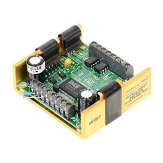
M e c h a n i c a l S p e c i f i c a t i o n s Shown is the standard 8 position screw terminal set for the IM483. Dimensions and specifications for the different connection options are available in Appendix A: Standard Connection Options, of this document. -
Page 11: Electrical Specifications
Ω * Includes motor back EMF. **Lower currents may be used for current reduction. Table 2.1: IM483 Electrical Specifications IM483 Operating Instructions Revision R032306... -
Page 12: Thermal Specifications
NOTE! This pin configuration diagram and table represent the pinout of any 8 position connector used for P1. If you purchased the IM483-34P1 option (34 Position Header) the pin configuration diagram and table is located in Appendix A: Standard Connection Options. -
Page 13: Table 2.3 Connector P1 - Pin Assignment And Description
Table 2.3: Connector P1 - Pin Assignment and Descriptions IM483 Operating Instructions Revision R032306... -
Page 14: Table 2.4 Connector P2 - Pin Assignment And Description
Ø Ø Table 2.4: Connector P2 - Pin Assignment and Descriptions WARNING! The IM483 components are sensitive to ElectroStatic Discharge (ESD). All handling should be done at an ESD protected workstation. WARNING! Hazardous voltage levels may be present if using an open frame power supply to power the IM483. -
Page 15: Mounting The Im483
IM483. Special mounting instructions for any of the connection options for the IM483 are available in Appendix A: Standard Connection Options, of this document. An optional heat sink and thermal pad, the H-4X and TN-48, are available for the IM483. See Appendix C: Cooling Solutions, for details. Thermal Pad... -
Page 16: Theory Of Operation
T h e o r y o f O p e r a t i o n S e c t i o n O v e r v i e w This section will cover the circuit operation for the IM483 microstepping driver. -
Page 17: Microstep Select (Msel) Inputs
This feature allows the user to switch resolutions at any time without having to keep track of sine/cosine location. Because of this, the On-Full-Step output of the IM483 can easily be used to monitor position. Configuration settings for the Microstep Resolution are located in Section 7 of this document, Interfacing and Controlling the IM483. -
Page 18: Dual Pwm Circuit
In the first part of its cycle, the PWM DRIVE CURRENT RECIRCULATION is in a non-recirculating mode to pull current from the motor windings. In Figure 4.3: Non-Recirculating PWM the second part of the cycle the PWM IM483 Operating Instructions Revision R032306... -
Page 19: Fullstep Output Signal
IM483 will execute the change before taking the next step. Only AFTER the change has been executed will the step be taken. If no change has occurred, the IM483 will simply take the next step. This feature works as an automatic debounce for the direction and microstep resolution select inputs. -
Page 20: Power Supply Requirements
T h e P o w e r S u p p l y - D r i v e r R e l a t i o n s h i p The IM483 is very current efficient as far as the power supply is con- cerned. -
Page 21: Table 5.1 Motor Power Supply Requirements
This could lead to an over voltage condition which could damage the output circuitry of the IM483. Non IMS switching power supplies and regulated linear supplies with overcurrent protection are not recommended because of their inability to handle the surge currents inherit in stepping motor systems. -
Page 22: Selecting An Opto Supply
R e c o m m e n d e d I M S P o w e r S u p p l i e s IMS has designed a series of low cost miniature unregulated switchers and unregulated linears which can handle extreme varying load condi- tions. -
Page 23: Recommended Wiring
R e c o m m e n d e d P o w e r S u p p l y C a b l e s Power supply cables must not run parallel to logic level wiring as noise will be coupled onto the logic signals from the power supply cables. IM483 Operating Instructions Revision R032306... -
Page 24: Ac Line Filtering
Since the output voltage of an unregulated power supply will vary with the AC input applied, it is recommended that an AC line filter be used to prevent damage to the IM483 due to a lightning strike or power surge. WARNING! Verify that the power supply wiring is correct prior to power application. -
Page 25: Motor Requirements
This means it has multiple phases wound in the stator and the rotor is dragged along in synchronism with the rotating magnetic field. The IM483 is designed to work with the following types of stepping motors:... - Page 26 W i n d i n g I n d u c t a n c e Since the IM483 is a constant current source, it is not necessary to use a motor that is rated at the same voltage as the supply voltage. What is important is that the IM483 is set to the motor’s rated current.
-
Page 27: Figure 6.1 Per Phase Winding Inductance
Figure 6.1 A & B: Per Phase Winding Inductance The per phase winding inductance specified may be different than the per phase inductance seen by your IM483 driver depending on the wiring configuration used. Your calculations must allow for the actual inductance that the driver will see based upon the wiring configuration. - Page 28 M-2222-3.0S ............M-2222-3.0D M-2231-3.0S ............M-2231-3.0D IMS also offers 17 and 23 Frame hybrid linear actuators for use with the IM483. Please see the IMS Full Line catalog or the IMS web site at http: //www.imshome.com. IM483 Operating Instructions Revision R032306...
- Page 29 I M S I n s i d e O u t S t e p p e r M o t o r s The new inside out stepper (IOS) motor was designed by IMS to bring versatility to stepper motors using a unique multi-functional, hollow core design.
-
Page 30: Motor Wiring
The motor leads are connected to the following connector pins: I M 4 8 3 Phase Connector: Pin Phase B ................ P2: 5 Phase B ................ P2: 6 Phase A ................ P2: 7 Phase A ................ P2: 8 IM483 Operating Instructions Revision R032306... -
Page 31: Figure 6.2 8 Lead Motor Series Connections
Multiply the per phase (or unipolar) current rating by 1.96, or the bipolar current rating by 1.4, to determine the peak output current. PHASE A PHASE A PHASE B PHASE B Figure 6.3: 8 Lead Motor Parallel Connections IM483 Operating Instructions Revision R032306... -
Page 32: Figure 6.4 6 Lead Motor Half Coil (Higher Speed) Connections
Use the per phase (or unipolar) current rating as the peak output current. PHASE A NO CONNECTION PHASE A PHASE B NO CONNECTION PHASE B Figure 6.5: 6 Lead Full Coil (Higher Torque) Motor Connections IM483 Operating Instructions Revision R032306... -
Page 33: Figure 6.6 4 Lead Motor Connections
In setting the driver output current, multiply the specified phase current by 1.4 to determine the peak output current. PHASE A PHASE A PHASE B PHASE B Figure 6.6: 4 Lead Motor Connections IM483 Operating Instructions Revision R032306... -
Page 34: Interfacing And Controlling The Im483
I M 4 8 3 S e c t i o n O v e r v i e w This section covers the interface connections, configuration and control signals of the IM483. Covered are: Layout and Interface Guidelines. Motor Power Connection (+V). -
Page 35: Motor Power Connection (+V)
M o t o r P o w e r C o n n e c t i o n ( + V ) Figure 7.1 illustrates the motor power (+V) connection to two IM483 drives using a recommended IMS ISP200-4 unregulated switching power supply. -
Page 36: Configuring And Controlling The Output Current
For any given motor, the output current used for microstepping is deter- mined differently from that of a half/full step driver. In the IM483, a sine/cosine output function is used in rotating the motor. Therefore, when microstepping, the specified phase current of the motor is considered an RMS value. - Page 37 NOTE! The PEAK current will be used to determine the current adjust resistor value, NOT the RMS current! This represents the maximum output current that should be set for your IM483 driver! 4 L e a d M o t o r s Multiply the specified phase current by 1.4 to determine the peak...
- Page 38 WARNING! Although stepping motors will run hot when configured correctly, damage may occur to a motor if a higher than specified current is used. In most cases, the specified motor currents are maximum values and should not be exceeded! IM483 Operating Instructions Revision R032306...
-
Page 39: Figure 7.2 Current Adjust Resistor Placement
Adjustment Resistor! A resistor MUST be placed between the Current Adjust Input (Pin 2 on P2) and ground (Pin 3 on P2) to keep the IM483 Driver and/or Figure 7.2 illustrates the connection of this resistor. Table 7.1 lists the resistor values for the driver output current in 200 milliamp increments. -
Page 40: Figure 7.3 Current Reduction Adjust Resistor Placement
R e d u c i n g / D i s a b l i n g t h e O u t p u t C u r r e n t The IM483 has the capability of automatically reducing the current in the motor windings following a move. -
Page 41: Controlling The Output Resolution
If remote control of the output resolution is required, these signals are brought out on connector P1 on the IM483-34P1. This option is discussed in detail in Appendix A: Standard Connector Options. MSEL3... -
Page 42: Table 7.2 Microstep Resolution Switch Settings
� � � � � � � � � � � � � � � � � � � � � � � � � � � � � � Table 7.2: Microstep Resolution Switch Settings IM483 Operating Instructions Revision R032306... -
Page 43: Interfacing And Using The Isolated Logic Inputs
Each input is internally pulled-up to the level of the optocoupler supply and may be connected to sinking outputs on a controller such as the IMS LYNX or a PLC. These inputs are:... -
Page 44: Table 7.3 Recommended Input Current Limiting Resistor Values
IM483’s input circuitry, rendering the drive I s o l a t e d L o g i c I n p u t C h a r a c t e r i s t i c s... -
Page 45: Table 7.4 Isolated Logic Input Timing
Please note that the internal sine/cosine position generator will continue to increment or decrement as long as step clock pulses are being received by the IM483. This input is asynchronous to any other input and may be changed at any time. -
Page 46: Figure 7.6 Switch Interface
Open Collector Interface. TTL Interface. We will also show IM483 inputs connected to the IMS LYNX modular mo- tion controller, which is a powerful machine control soulution. S w i t c h I n t e r f a c e A switch connected between the input and the opto supply ground will sink the input. -
Page 47: Figure 7.7 Open Collector Interface
Figure 7.8 shows a TTL device connected to the enable input. This inter- face method may be used with any of the logic inputs. +5 VDC MSEL3 MSEL2 MSEL1 MSEL0 CONTROLLER Opto Supply P1:4 OUTPUT Enable P1:5 Figure 7.8: TTL Interface IM483 Operating Instructions Revision R032306... -
Page 48: Figure 7.9 Lynx Interface
Figure 7.9 shows a LYNX Control Module and Differential I/O Module providing step clock, direction and optocoupler supply voltage to two IM483 drivers. The LYNX isolated I/O may also be used to control the enable and reset inputs, the MSEL inputs (IM483-34P1) and receive feed- back from the fault and fullstep outputs. -
Page 49: Connecting And Using The Fault Output
C o n n e c t i n g a n d U s i n g t h e F a u l t O u t p u t The IM483 has an open collector fault output located on P1:7. This output is non-isolated and has the ability of sustaining maximum driver voltage. -
Page 50: Full Step Output
As noted in the drawing, this is only a representation of a possible application of the full step output. Additional interface circuitry may be required between the IM483 and the counter. Check the documentation provided by the manu- facturer of your counter for interface requirements. -
Page 51: Minimum Connections
ØA ��� Direction ØA ØB ØB � +5 VDC ������������������� Opto ������������������� Supply Current Adjustment SUPPLY AND MOTOR WIRING: Resistor Use 18 AWG twisted pair. P2:1 (Belden #9740 or equivalent) Figure 7.12:IM483 Minimum Required Connections IM483 Operating Instructions Revision R032306... -
Page 52: Troubleshooting
B a s i c T r o u b l e s h o o t i n g In the event that your IM483 doesn’t operate properly, the first step is to identify whether the problem is electrical or mechanical in nature. The next step is to isolate the system component that is causing the prob- lem. - Page 53 • P o s s i b l e P r o b l e m Incorrect current adjust setting or resistor value. Motor is undersized for application. Acceleration on controller is set too high. Power supply voltage too low. IM483 Operating Instructions Revision R032306...
- Page 54 Inadequate holding torque. • P o s s i b l e P r o b l e m Incorrect current adjust setting or resistor value. Increase holding current with the current reduction adjust resistor. IM483 Operating Instructions Revision R032306...
-
Page 55: Contacting Technical Support
C o n t a c t i n g Te c h n i c a l S u p p o r t In the event that you are unable to isolate the problem with your IM483, the first action you should take is to contact the distributor from whom you originally purchased your product or IMS Technical Support at 860- 295-6102 or by fax at 860-295-6107. -
Page 56: Appendix A: Standard Connection Options
The P1 connector location uses 8 -0.025 square pins. This connector style would be advantageous in a scenario where the user desires to either solder or plug the IM483 directly into a system PCB. Dimen- sions and PCB hole patterns are given later in this appendix. -
Page 57: Im483-34P1
Applicable Products: IM483-34P1 Figure A.1: IM483-34P1 Connector P1 Mechanical Drawing P i n C o n f i g u r a t i o n / D e s c r i p t i o n Figure A.2 and Table A.1 show the pin location and description of the 34 pin... -
Page 58: Table A.1: Im483-34P1 Connector P1Pin Assignment And Description
. t u t u l t u l . t u t u l t u l . t u . e l Table A.1: IM483-34P1 Connector P1Pin Assignment and Description IM483 Operating Instructions Revision R032306... - Page 59 The microstep resolution is synchronized with the step clock input. If the resolution change does not fall on a full step, the IM483 will readjust itself at the next pulse that would overshoot the fullstep position. This feature allows the IM483 to readjust the motor position regardless of the output resolution selected during a resolution change.
-
Page 60: Figure A.3 Msel Connection Using Ttl Interface
� � ��� � � � � ��� � � � � ������������������������������������� ������ ������ ������ ������ ������������������������ ������� � � � � ������� � � � � Figure A.3: MSEL Connection Using TTL Interface IM483 Operating Instructions Revision R032306... -
Page 61: Figure A.4 Cascading Im483-34P1 Drives Using The Step/Direction Outputs
S t e p C l o c k a n d D i r e c t i o n O u t p u t s Another key feature offered by the IM483-34P1 is the non-isolated step clock and direction outputs. These outputs will follow the step and direction inputs. -
Page 62: Im483-8P2
The P1 connector location uses 8 -0.025 square pins. This connector style is advantageous in a scenario where the user desires to either solder the IM483 directly into a system PCB or wire-wrap the interface connections. Figures A.5 and A.6 show the pin dimensions. -
Page 63: Figure A.7 Im483-8P2 Pcb Hole Pattern
P C B H o l e P a t t e r n The IM483-8P2 is ideal for solder-mounting into a user’s PC board design. Figure A.7 illustrates the PCB hole pattern as well as the recommended hole and pad diameter for the IM483-8P2. -
Page 64: Im483-34P1-8P2
I M 4 8 3 - 3 4 P 1 - 8 P 2 This option combines the features and potential uses of the IM483-34P1 and the IM483-8P2. The connec- tor pins used for connector P2 are identical to those used on the IM483-8P2. -
Page 65: Figure A.10 Im483-34P1-8P2 Pcb Hole Pattern
P C B H o l e P a t t e r n The IM483-34P1-8P2 is ideal for solder-mounting into a user’s PC board design. Figure A.10 illustrates the PCB hole pattern and recommended pad diameter for the IM483-8P2. -
Page 66: Im483-Plg
I n t e r f a c i n g t h e A d d i t i o n a l I / O o n C o n n e c t o r P 1 The MSEL inputs and Step/Direction outputs on the IM483-34P1-8P2 are interfaced in the same way as those on the IM483-34P1. See the part of this appendix pertaining to that model of the IM483 for interface and connec- tion details. -
Page 67: Figure A.12 Im483-Plg Pin Location And Orientation
MSEL3 MSEL2 MSEL1 MSEL0 Figure A.12: IM483-PLG Pin Location and Orientation IM483 Operating Instructions Revision R032306... -
Page 68: Appendix B: Input Options
Table B.1: IM483-DC, Connector P1 Pin Assignment and Description IM483 Operating Instructions Revision R032306... -
Page 69: Figure B.1 Im483-Dc Connection
To switch the direction of the motor with respect to the CW and CCW step clock inputs, switch the wires on either Phase A or Phase B outputs. IM483 Operating Instructions Revision R032306... -
Page 70: Appendix C: Cooling Solutions
0.65 W/m-K and a maximum temperature rating of 180°C. One side of the TN-48 pad is adhesive and may be applied directly to the IM483 driver. The TN-48 pad eliminates the problems associated with using thermal grease. This pad are also included in the heat sink kit. -
Page 71: Appendix D: Accessories
U 3 - C L P : S i d e - M o u n t i n g C l i p The U3-CLP mounting clips were specially designed for the IM80X, IM483 series of Microstepping drivers and driver indexers and the ISP200 and ISP300 series power supplies to decrease overall panel space and allow for more flex- ible mounting patterns. -
Page 72: Figure D.2 Attaching The U3-Clp To The Im483
M o u n t i n g The unit should be mounted in ac- Figure D.2: Attaching the U3-CLP to the IM483 cordance with Figure D.3 using the recommended hardware. Ensure that mounting hardware doesn’t in- terfere with any circuitry or wiring. -
Page 73: Bb-34-4P Breakout Board
S p e c i f i c a t i o n s a n d W i r i n g R e c o m m e n d a t i o n s IMS recommends that the following wiring practices be used to interface to the IM483-34P1 using the BB-34-4P: Wire Size: 16 - 22 AWG Strip Length: 0.200”... -
Page 74: Figure D.5 Bb-34-4P Pin Locations
#M3 Flat Washer, Stainless (.05 TH, 6.20 OD) Driver Connector P1 Thermal Pad IMS TN-48 or Equivalent Mounting Screw Torque: 5.0 to 7.0 lb-in (0.60 to 0.80 N-m) Heat Sink Plate Figure D.6: BB-34-4P Mounting Diagram IM483 Operating Instructions Revision R032306... -
Page 75: Plg-R Removable Screw Terminal Set
P1 and P2. Replacement terminals may be ordered individually as needed. The order num- bers for individual replacements are: Connector P1 ............. PLG-R2 Connector P2 ............. PLG-R1 IM483 Operating Instructions Revision R032306... -
Page 76: Appendix E: Recommended Cable Configurations
Cable length, wire gauge and power conditioning devices play a major role in the performance of your IMS Driver and Motor. NOTE: The length of the DC power supply cable to the IMS Driver should not exceed 50 feet. Example A demonstrates the recommended cable configuration for DC power supply cabling under 50 feet long. - Page 77 P o w e r t o F u l l W a v e B r i d g e ����� ���������� ����������������������������� ���������������������������� � �������������������� ���������������� ������������ ����������� ��������������������� ��������������� ���������������������������������� π ���������������� ≥����������������� ���������������������� �������������� ������������������ ���������������� ������������������ ���������������� ������������������ IM483 Operating Instructions Revision R032306...
- Page 78 P o w e r t o P o w e r S u p p l y ������������ ����� ���������� � ����������������������������� ����������������������������� ���������������� ������������ ������������ ����������� ��������������������� ��������������� ���������������������������������� π ���������������� ≥����������������� ���������������������� ������������������ �������������� ������������ ������������ IM483 Operating Instructions Revision R032306...
- Page 79 Also, use the same current rating when the alternate AC power is used. Driver Supply Cable Wire Size NOTE: Always use Shielded/Twisted Pairs for the IMS Driver DC Supply Cable, the AC Supply Cable and the IMS Driver to Motor Cable. IM483 Operating Instructions Revision R032306...
- Page 80 Motor should not exceed 50 feet. Example A demonstrates the recommended cable configuration for the IMS Driver to Motor cabling under 50 Feet long. If cabling of 50 feet or longer is required, the additional length can be gained with the cable configuration in Example B.
- Page 81 D r i v e r t o M o t o r ������� ������� ������� ������� ������� ����� ������������ ������������������ �������������������������� ��������������� ������������������������������������ ������� ������� ���������������������� ����������� ������������������ ����������������� ������� ������� ���≈������� �������������������������������������������� ���������������������������������������� ���������������������������������������������� ����������������������������������������������������� IM483 Operating Instructions Revision R032306...
- Page 82 NOTE: Always use Shielded/Twisted Pairs for the IMS Driver DC Supply Cable, the AC Supply Cable and the IMS Driver to Motor Cable. IM483 Operating Instructions Revision R032306...
- Page 83 Limited Warranty shall be the repair or replacement, at Company’s sole option, of the Product, or any part of the Product, determined by IMS to be defective. In order to exercise its warranty rights, Customer must notify Company in accordance with the instructions described under the heading “Obtaining Warranty Service.”...
Need help?
Do you have a question about the IM483 and is the answer not in the manual?
Questions and answers
Subject: where to go to get a n expert on stepper motor drivers We have some great drivers that I purchased but do not know how to hook them up properly. Product: INTELLIGENT MOTION SYSTEMS,INC MARLBOROUGH, CT Item IM483I Stepper motor driver. VERY WILLING TO PAY FOR HELP. I HAVE ABOUT 16 OF THEM THAT ARE WORTH $200 EACH or zero if I can not get them working. Any site I can go to? Fred M. Schwartz Quality One Engravers, Inc. 9749 Crescent Center Dr. Unit 202 Rancho Cucamonga, CA 91730 P 909-989-3898 www.q1engravers.com