Sign In
Upload
Manuals
Brands
IMS Manuals
Controller
IM483
IMS IM483 Manuals
Manuals and User Guides for IMS IM483. We have
4
IMS IM483 manuals available for free PDF download: Operating Instructions Manual, Quick Reference
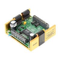
IMS IM483 Operating Instructions Manual (83 pages)
high performance microstepping drive
Brand:
IMS
| Category:
Controller
| Size: 2.36 MB
Table of Contents
Table of Contents
3
Introduction
7
The IM483
7
Features and Benefits
7
The Product Manual
8
The Product Manual
9
Notes and Warnings
9
Hardware Specifications
10
Section Overview
10
Mechanical Specifications
10
Figure 2.1 IM483 Dimensions
10
Electrical Specifications
11
Table 2.1 Electrical Specifications
11
Thermal Specifications
12
Pin Assignment and Description
12
Figure 2.2 IM483 Pin Configuration
12
Table 2.2 IM483 Thermal Specifications
12
Table 2.3 Connector P1 - Pin Assignment and Description
13
Table 2.4 Connector P2 - Pin Assignment and Description
14
Mounting the IM483
15
Figure 3.1 Mounting Recommendations
15
Theory of Operation
16
Section Overview
16
Circuit Operation
16
Figure 4.1 IM483 Block Diagram
16
Microstep Select (MSEL) Inputs
17
Stepping
17
Dual PWM Circuit
18
Figure 4.2 Recirculating PWM
18
Figure 4.3 Non-Recirculating PWM
18
Fullstep Output Signal
19
Timing
19
Power Supply Requirements
20
Section Overview
20
Selecting a Power Supply
20
Table 5.1 Motor Power Supply Requirements
21
Selecting an Opto Supply
22
Table 5.2 +5 VDC Power Supply Requirements
22
Recommended Wiring
23
AC Line Filtering
24
Motor Requirements
25
Section Overview
25
Selecting a Motor
25
Figure 6.1 Per Phase Winding Inductance
27
Motor Wiring
30
Connecting the Motor
30
Figure 6.2 8 Lead Motor Series Connections
31
Figure 6.3 8 Lead Motor Parallel Connections
31
Figure 6.4 6 Lead Motor Half Coil (Higher Speed) Connections
32
Figure 6.5 6 Lead Motor Full Coil (Higher Torque) Connections
32
Figure 6.6 4 Lead Motor Connections
33
Interfacing and Controlling the IM483
34
Section Overview
34
Layout and Interface Guidelines
34
Motor Power Connection (+V)
35
Configuring and Controlling the Output Current
36
Figure 7.1 IM483 Motor Power Connections
36
Figure 7.2 Current Adjust Resistor Placement
39
Table 7.1 Current Adjust Resistor Values
39
Figure 7.3 Current Reduction Adjust Resistor Placement
40
Controlling the Output Resolution
41
Figure 7.4 MSEL Switch Showing 50 Microsteps/Step Selected
41
Table 7.2 Microstep Resolution Switch Settings
42
Interfacing and Using the Isolated Logic Inputs
43
Figure 7.5 Optically Isolated Inputs
43
Table 7.3 Recommended Input Current Limiting Resistor Values
44
Table 7.4 Isolated Logic Input Timing
45
Figure 7.6 Switch Interface
46
Figure 7.7 Open Collector Interface
47
Figure 7.8 TTL Interface
47
Figure 7.9 LYNX Interface
48
Connecting and Using the Fault Output
49
Figure 7.10 the Fault Output Connected to an LED
49
Full Step Output
50
Figure 7.11 the Full Step Output Connected to an Up/Down Counter
50
Minimum Connections
51
Figure 7.12 IM483 Minimum Required Connections
51
Minimum Connections
52
Troubleshooting
52
Section Overview
52
Basic Troubleshooting
52
Problem Symptoms and Possible Causes
52
Contacting Technical Support
55
The IMS Web Site
55
Returning Your Product to IMS
55
Section Overview
52
Troubleshooting
52
Appendix A: Standard Connection Options
56
Appendix Overview
56
Im483-34P1
57
Figure A.1 IM483-34P1 Connector P1 Mechanical Drawing
57
Figure A.2: IM483-34P1Connector P1Pin Locations
57
Table A.1: IM483-34P1 Connector P1Pin Assignment and Description
58
Figure A.3 MSEL Connection Using TTL Interface
60
Figure A.4 Cascading IM483-34P1 Drives Using the Step/Direction Outputs
61
Im483-8P2
62
Figure A.5 IM483-8P2 - Connector P1
62
Figure A.6 IM483-8P2 - Connector P2
62
Figure A.7 IM483-8P2 PCB Hole Pattern
63
Im483-34P1-8P2
64
Figure A.8 IM483-34P1-8P2 - Connector P1
64
Figure A.9 IM483-34P1-8P2 - Connector P2
64
Figure A.10 IM483-34P1-8P2 PCB Hole Pattern
65
Im483-Plg
66
Figure A.11 IM483-PLG Connectors
66
Figure A.12 IM483-PLG Pin Location and Orientation
67
Appendix B: Input Options
68
Im483-DC
68
Table B.1 IM483-DC - Connector P1 Pin Assignment and Description
68
Figure B.1 IM483-DC Connection
69
Appendix C: Cooling Solutions
70
H-4X Heat Sink Kit
70
Thermal Non-Isolating Pad (TN-48)
70
Figure C.1 H-4X Heat Sink
70
Appendix D: Accessories
71
Appendix Overview
71
Figure D.1 U3-CLP Mounting Hole Locations
71
U3-CLP: Side-Mounting Clip
71
Figure D.2 Attaching the U3-CLP to the IM483
72
Figure D.3 Panal Mounting an IM483 Using the U3-CLP Clip Set
72
BB-34-4P Breakout Board
73
Figure D.4 BB-34-4P Breakout Board Mechanical Specifications
73
Figure D.5 BB-34-4P Pin Locations
74
Figure D.6 BB-34-4P Mounting Diagram
74
PLG-R Removable Screw Terminal Set
75
Appendix E: Recommended Cable Configurations
76
Advertisement
IMS IM483 Quick Reference (2 pages)
HIGH PERFORMANCE MICROSTEPPING DRIVER
Brand:
IMS
| Category:
Control Unit
| Size: 0.19 MB
IMS IM483 Quick Reference (2 pages)
HIGH PERFORMANCE MICROSTEPPING DRIVER
Brand:
IMS
| Category:
DC Drives
| Size: 0.24 MB
Advertisement
IMS IM483 Quick Reference (2 pages)
HIGH PERFORMANCE MICROSTEPPING DRIVER
Brand:
IMS
| Category:
DC Drives
| Size: 0.19 MB
Advertisement
Related Products
IMS IC32T
IMS IC32F
IMS IC60T
IMS IC60F
IMS Installer's Choice IC71TH
IMS Installer's Choice IC71FH
IMS Installer's Choice IC71T
IMS Installer's Choice IC71F
IMS IB462H
IMS IMSAI 8080
IMS Categories
Welding System
DC Drives
Industrial Equipment
Computer Hardware
Home Safety Product
More IMS Manuals
Login
Sign In
OR
Sign in with Facebook
Sign in with Google
Upload manual
Upload from disk
Upload from URL