
Related Manuals for IMS Smart Cap 485


Summary of Contents for IMS Smart Cap 485
- Page 1 Smart Cap 485 Controlador de Fator de Potência POWER FACTOR CONTROLLER Manual de Instalação e Operação Maio/2006 Revisão do manual 2.23 Cód. IMS 0150015G www.ims.ind.br ims@ims.ind.br...
- Page 2 é primordial para a sua segurança. antes de iniciar a instalação do equipamento, leia atentamente todas as instruções contidas neste manual. em caso de dúvida favor entrar em contato conosco. IMS – Soluções em Energia Ltda. www.ims.ind.br ims@ims.ind.br Fone: (51) 3382.2300...
-
Page 3: Table Of Contents
Manual de Instalação e Operação INDICE 1. APRESENTAÇÃO DO SMART CAP 485 ........6 2. CaracterÍsticas Técnicas ..............6 3. DESCRIÇÃO FÍSICA ..............7 3.1. Painel Frontal ................. 7 3.2. Painel Traseiro ............... 8 4. INSTALAÇÃO ................10 4.1. Alimentação ................. 10 4.2. - Page 4 TERMO DE VALIDADE DE CALIBRAÇÃO IMS ..... 31 RELATÓRIO À ASSISTÊNCIA TÉCNICA ......... 32 ENGLISH ..................33 1. PRESENTATION OF THE SMART CAP 485 ......34 2. TECHNICAL CHARACTERISTICS ......... 34 3. PHYSICAL DESCRIPTION ............35 3.1. FRONT PANEL ..............35 3.2.
- Page 5 10.3. CURRENTS ............... 56 10.4. TOTAL VALUES (Three phases) ........56 10.5. POWERS ................56 10.6. Thd AND HARMONICS ........... 57 10.7. FREQUENCY ..............57 10.8. NUMBER OF COMMUTATIONS ........57 11. PROBLEMS SOLUTION ............58 WARRANTY TERM ..............59 SMART CAP 485...
-
Page 6: Apresentação Do Smart Cap 485
O Smart Cap 485 realiza medições de tensão ( F-F ou F-N ) e sinais de corrente proveniente da rede elétrica, com os quais calcula e indica em valor eficaz (RMS) as grandezas elétricas de tensão;... -
Page 7: Descrição Física
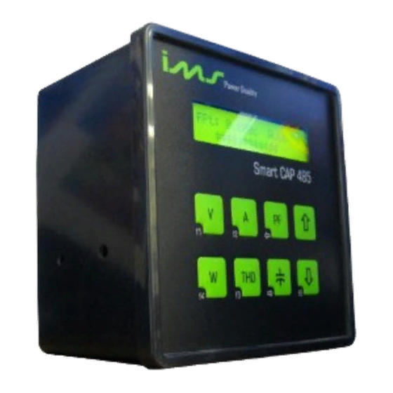
3.1. PAINEL FRONTAL Toda a operação e monitoração do Smart Cap 485, pode ser feita através do seu painel frontal que apresenta 1 display de cristal líquido de 2 linhas por 20 colunas e 8 teclas de membrana. -
Page 8: Painel Traseiro
Decrementa, ou passa para tela anterior. Ativa segunda função de outras teclas. 3.2. PAINEL TRASEIRO Através do painel traseiro são realizadas todas as conexões do Smart Cap 485. A figura a seguir apresenta o seu painel traseiro. SMART CAP 485... - Page 9 Manual de Instalação e Operação 3.2.1. CONECTOR DE ALIMENTAÇÃO É o conector onde deve ser ligada a energia que alimenta o Smart Cap 485. Neste conector não há nenhuma conexão com a tensão monitorada, servindo apenas para alimentar o equipamento.
-
Page 10: Instalação
270Vca a freqüência de 45 a 65Hz. Esta ligação é somente para a alimentação do equipamento. O aterramento do equipamento também é feito neste conector. O Smart Cap 485 não possui um botão “POWER ON”, é ligado no momento em que é alimentado. -
Page 11: Esquema De Ligação Das Entradas
R (V1), fase S (V2) e fase T (V3). Ligue os TC’s aos bornes conforme a figura ao lado. Ligação a três TC's: Quando o Smart Cap 485 for programado para medição a dois (2) TC's não é necessário à ligação do TC referente à fase V2 (I2). Porém nesta configuração de dois TC's a corrente da fase V2 será... - Page 12 Manual de Instalação e Operação 4.2.2.1. SENSOR DE TENSÃO FASE-NEUTRO SEM TP 4.2.2.2. SENSOR DE TENSÃO FASE-NEUTRO COM TP SMART CAP 485...
- Page 13 Manual de Instalação e Operação 4.2.2.3. SENSOR DE TENSÃO FASE-FASE SEM TP 4.2.2.4. SENSOR DE TENSÃO FASE-FASE COM TP SMART CAP 485...
-
Page 14: Esquema De Ligação Das Saídas
Cada saída de acionamento possuí capacidade para acionar contatoras com até 105VA de potência e corrente de partida menor ou igual a 10A. Por exemplo: contatoras modelo Siemens 3TF54/55, WEG CW297/22, INEPAR JMC300, Scheneider-Telemecanique LC1F330 ou equivalentes ou menores. SMART CAP 485... -
Page 15: Simbologia
Para bloquear ou desbloquear o teclado pressione a tecla F0 seguida da tecla F4. Enquanto o teclado estiver bloqueado é exibido o símbolo de uma chave no canto superior direito do display, e pressionando qualquer tecla diferente da tecla F0 será exibida a mensagem de teclado protegido. SMART CAP 485... -
Page 16: Programação
Manual de Instalação e Operação 7. PROGRAMAÇÃO Quando o Smart Cap 485 estiver devidamente instalado no painel, e antes de permitir que os bancos de capacitores sejam acionados, deve ser feita a sua programação para configurar os parâmetros da rede elétrica em que ele deve corrigir o fator de potência, e também os parâmetros dos bancos de capacitores instalados. -
Page 17: Modo De Operação
Assim o controlador vai adicionando os bancos de capacitores de acordo com a potência requerida até atingir a faixa de fator de potência desejada. Caso o fator de potência ultrapasse o limite superior programado, o Smart Cap 485 vai começar a retirar bancos de capacitores, iniciando pelo de menor potência reativa. -
Page 18: Utilização Das Teclas De Programação
OBS.: A função em modo manual comanda todas as saídas independente do tempo de entrada ou saídas programadas. Uma vez programado em modo manual, o Smart Cap 485 permanecerá neste modo até que uma nova programação seja realizada, mesmo que ocorra a falta de energia durante este período. -
Page 19: Menu Programação
Estes parâmetros mostram a relação de transformação de potencial de tensão . Valor, max. 500kV e min.50V. Relação de transformação de corrente. Max. 65000 e min. 1 Programe de acordo com a instalação do equipamento. Tecle ↑ para ligação em Delta e ↓ para estrela. SMART CAP 485... -
Page 20: Modo De Controle
O banco ativo para a troca de estado fica piscando na tela, e o seu respectivo número é mostrado no canto inferior esquerdo do display. Pressione as setas ↑ ou ↓ para acionar ou desligar o banco de capacitores, ou pressione F1 para passar ao próximo banco. Para trocar de tela pressione F4. SMART CAP 485... -
Page 21: Zerando Os Registros De Números De Comutações
Pressionando F1 todos os registros de números de comutações dos bancos de capacitores serão zerados. O número de comutação de cada banco de capacitores é utilizado pelo Smart Cap 485, para aumentar a vida útil dos bancos. 9.5.PROGRAMAÇÃO DA FAIXA DE CONTROLE Pressione F1 para confirmar e entrar na tela de programação do parâmetro. - Page 22 O tempo de saída e de entrada do banco de capacitores são parâmetros úteis para a proteção e prolongamento da vida útil do banco de capacitores. Estes parâmetros afetam apenas o acionamento dos bancos de capacitores quando o Smart Cap 485 estiver funcionando no Modo Automático.
- Page 23 é equivalente a 50% do primário do TC. FASE DE CONTROLE A configuração da fase de controle estabelece para o Smart Cap 485 sobre que medição de fator de potência ele deve fazer o controle, podendo ser pela fase 1, 2, 3 ou pelo valor médio das três fases.
-
Page 24: Habilitação Das Saídas
Proceda da mesma forma para os valores das telas a seguir (Vmax2, Vmin2, Vmax3, Vmin3, Imax1, Imin1, Imax2, Imin2, Imax3, Imin3, FPmax1, FPmin1, FPmax2, FPmin2,FPmax3, FPmin3, THD_V1, THD_V2,, THD_V3, ). Para o alarme de THD a medição de harmônico deve estar habilitada. SMART CAP 485... -
Page 25: Comunicação Serial
Manual de Instalação e Operação 9.10. COMUNICAÇÃO SERIAL Estes parâmetros definem como o Smart Cap 485 será reconhecido ao ser conectado em rede. Endereço de rede de 1 até 250 e velocidade de comunicação de 9600,19200, e 38400bps. 9.11. HARMÔNICAS Vá... -
Page 26: Fator De Potência
10.1.1. FATOR DE POTÊNCIA E ESTADO DOS BANCOS A primeira tela visualizada no display após a inicialização do Smart Cap 485 é a tela que mostra o valor do fator de potência da fase de controle, o modo de controle (AUTO ou Manual), o estado dos bancos de capacitores, ou seja, se eles estão ligados, desligados ou... -
Page 27: Tensões
Pressionando W será mostrado a tela com as medições trifásicas de potência (Wt), potência aparente total (VAt) e potência reativa total (VArt). Pressionando as setas ↓ e ↑ serão exibidas as telas com as medições de potência por fase. SMART CAP 485... -
Page 28: Thd E Harmônicas
Pressionando THD novamente é mostrado o valor da freqüência elétrica da rede. 10.8. NÚMERO DE COMUTAÇÕES é mostrada a tela com o número de comutações. Utilize as setas ↓ e ↑ Pressionando para trocar o banco de capacitores visualizado. SMART CAP 485... -
Page 29: Solução De Problemas
Solução: verificar se existe a ligação na entrada da fase L1 ou se o nível de tensão aplicada está dentro da faixa especificada. Qualquer dúvida favor entrar em contato com nossa assistência técnica pelos telefones (51) 2131 3322 ou pelo e-mail: ims@ims.ind.br. SMART CAP 485... -
Page 30: Termo De Garantia
TERMO DE GARANTIA Prezado cliente, Ao adquirir equipamentos da IMS você tem a garantia por um ano, a partir da data da emissão da nota fiscal, contra defeitos de fabricação. Esta garantia compreende o conserto, incluindo peças e mão de obra, do equipamento. -
Page 31: Termo De Validade De Calibração Ims
TERMO DE VALIDADE DE CALIBRAÇÃO IMS Prezado cliente, Sugerimos que o equipamento retorne a IMS para nova calibração após 1 (um) ano, a partir da data de emissão da nota fiscal. Para calibrar seus equipamentos a IMS utiliza como padrão o CALIBRADOR FLUKE 5500A. -
Page 32: Relatório À Assistência Técnica
Manual de Instalação e Operação RELATÓRIO À ASSISTÊNCIA TÉCNICA DADOS DA EMPRESA NOME DA EMPRESA: ENDEREÇO PARA ENTREGA DO EQUIPAMENTO: CIDADE: FONE: ( FAX: ( E-MAIL: CONTATO: TRANSPORTADORA: DADOS DO EQUIPAMENTO EQUIPAMENTO: NÚMERO DE SÉRIE: DEFEITOS APRESENTADOS: CAUSAS POSSÍVEIS: SMART CAP 485... -
Page 33: English
PRIMORDIAL FOR YOUR SAFETY. BEFORE INITIATING THE EQUIPMENT INSTALLATION, READ WITH ATTENTION ALL THE INSTRUCTIONS CONTAINED IN THIS MANUAL. IN CASE OF DOUBT PLEASE GET IN CONTACT. IMS – Soluções em Energia Ltda www.ims.ind.br ims@ims.ind.br Phone: +55 51 3382.2300 SMART CAP 485... -
Page 34: Presentation Of The Smart Cap 485
The Smart Cap 485 makes voltage measurements ( P-P or P-N ) and current signals coming from the electric net, with which it calculates and indicates in effective value (RMS) the electric magnitude of voltage;... -
Page 35: Physical Description
3.1. FRONT PANEL All the operation and monitoring of Smart Cap 485, can be made through its front panel that presents 1 display of liquid crystal of 2 lines by 20 columns and 8 membrane keys. The side illustration presents its front panel. -
Page 36: Back Panel
It decreases or passes to previous screen. Activates second function of other keys. 3.2. BACK PANEL Through the back panel they are made all the connections of Smart Cap 485. The following illustration presents its back panel. SMART CAP 485... - Page 37 CT. Usually, this connection is made through current transformers (CT’s). If there are not CT the connection should be made directly. Respecting the maximum limit of 5A. IMPORTANT: The current, in this connector, should not surpass SMART CAP 485...
-
Page 38: Installation
- Phases of the electric system correctly identified, electric facilities and earthing of the system in perfect conditions. The Smart Cap 485 should be installed in a box or panel that has complete sealing against dust and water sprinkles. This box or panel also should protect it against mechanical shocks, vibrations and high temperatures. -
Page 39: Inputs Connection Scheme
Make sure that the CT's polarity is not inverted and its common is not connected for other application. Also it is compulsory the connection in the correct order of the phase R (V1), phase S (V2) and phase T (V3). Connect CT’s to terminals as the side illustration. Connection to three CT's: SMART CAP 485... - Page 40 Manual de Instalação e Operação When the Smart Cap 485 is programmed for measurement with two (2) CT's it is not necessary the CT connection regarding the phase V2 (I2). However in this setup of two CT's the current of phase V2 will be calculated and not measured, considering that the net is balanced.
- Page 41 Fase – Neutro S/TP. Ligação estrela = Phase-Neutral w/PT. Star connection 4.2.2.4. PHASE – PHASE VOLTAGE SENSOR WITH PT TENSÃO 50-500VAC = (Voltage 50-500Vac) Bornes = Terminals Rede = Net Fase – Neutro S/TP. Ligação estrela = Phase-Neutral w/PT. Star connection SMART CAP 485...
-
Page 42: Outputs Connection Scheme
If possible, do not use the same phase for the device feeding and for contactors feeding and install noise suppressors in contactors coils. The noise suppressor should be done as contactor manufacturer specification, or in the case of not existing it can be a series RC circuit (R=100ohm and C=0,1uF). SMART CAP 485... -
Page 43: Symbology
They represent the control outputs of the capacitors banks. Indication of protected keyboard. Arrows that indicate more screens inside a menu. On: It means that this stage output is connected. Off: It means that this stage output is disconnected. SMART CAP 485... -
Page 44: Keyboard Blockade
These data should be correctly setup in the equipment, because all the calculations that Smart Cap 485 does are based in them, so an incorrect specification can cause a bad equipment operation giving fines. -
Page 45: Operation Mode
THD FILTER 8. OPERATION MODE As soon as connected the Smart Cap 485 gets in operation showing the equipment type and the software version. The initial screen shows the power factor of the control phase and the control mode “Auto” or “Manual”. At this point the equipment stays in continuous measurement and calculation process. -
Page 46: Manual Mode
Thus the controller goes adding capacitors banks according to the required power until reaching the wished power factor band. In case the power factor surpasses the programmed upper limit, the Smart Cap 485 is going to start to withdraw capacitors banks, initiating by the one of smaller reactive power. -
Page 47: Programming Menu
Press F1 again to come into the screen below, to setup the items described as follows. (Prog. PT/CT, Ligação = Connection , Confirmar = Confirm, Sair = Out) These parameters show the voltage transformation relation. Value, max. 500kV and min.50V. SMART CAP 485... -
Page 48: Control Mode
Program according to the equipment installation. • Type ↑ f or automatic control (auto). • Type ↓ f or manual control. 9.3. MANUAL ACTUATION OF THE CAPACITORS BANKS This screen is for capacitors banks manual actuation. Press F1 to confirm. SMART CAP 485... -
Page 49: Zero The Commutations Numbers Records
Go to the screen below using the key F1 and the arrows. Pressing F1 all the records of commutations numbers of capacitors banks will be taken to zero. The number of commutations of each capacitors bank is used by Smart Cap 485, to increase the useful life of the banks. -
Page 50: Programming Of Parameter Of Banks Control
The times of output and input of capacitors bank are useful parameters for the protection and extending of the useful life of capacitors bank. These parameters affect only capacitors banks activation when Smart Cap 485 is working on Automatic Mode. MINIMUM REACTIVE POWER (KVAR IMIN):... - Page 51 Press the arrows to adjust the value of reactive power for the minimum current and press F1 to confirm the alteration. SMART CAP 485...
- Page 52 50% of the CT primary. CONTROL PHASE The control phase setup establishes for Smart Cap 485 about witch power factor measurement it should do the control, it could be by phase 1, 2, 3 or by the medium value of the three phases.
-
Page 53: Outputs Enabling
The value of each capacitor bank can be setup in a value between range of 0,1kVAr and 999,9kVAr. 9.9. ALARMS To program the alarms: Key (Lig.) and confirm keying “F1” and will appear in the below screen. Hab. Alarmes = Alarms enabling The slider will be in the máx1 value. SMART CAP 485... -
Page 54: Serial Communication
For THD's alarm the harmonic measurement should be enabled. 9.10. SERIAL COMMUNICATION These parameters define how Smart Cap 485 will be recognized when being connected in the net. The net address from 1 until 250 and communication speed of 9600,19200 and 38400bps. -
Page 55: Supervision / Monitoring
To attend this eventual need the Smart Cap 485 has the setup "Prog. Filter THD" that after enabled (On) that the activation output number 1 be made available for activation of the harmonics filter. -
Page 56: Voltages
Pressing W it will be shown the screen with the three phase measurements of power (Wt), total apparent power (VAt) and total reactive power (VArt). Pressing the arrows and it will be exhibited the screens with the power measurements per phase. SMART CAP 485... -
Page 57: Thd And Harmonics
10.7. FREQUENCY Pressing THD again it is shown the net electric frequency value. 10.8. NUMBER OF COMMUTATIONS Pressing it is shown the screen with the number of commutations. Use the arrows and to change visualized capacitors bank. SMART CAP 485... -
Page 58: Problems Solution
Solution: verify if there exist the connection in the input of phase L1 or if the level of the applied voltage is inside the specified range. Any doubt please get in touch with our technical assistance by the phones +55 51 3382.2300 or by the e-mail: ims@ims.ind.br. SMART CAP 485... -
Page 59: Warranty Term
Av. Bernardino Silveira Pastoriza, 720 Sarandí Porto Alegre – RS CEP.: 91160-310 The equipment should be sent to IMS accompanied of invoice and of the REPORT TO THE TECHNICAL ASSISTANCE. To avoid transport damages we suggest that the equipment be carefully packed, we advise the use of the package supplied by IMS. - Page 60 TERM OF CALIBRATION VALIDITY IMS Dear customer, We suggest that the equipment returns to IMS for new calibration after 1 (one) year, from the invoice emission date. To calibrate its equipments the IMS uses as standard the GAUGE FLUKE 5500A.
- Page 61 Manual de Instalação e Operação REPORT TO THE TECHNICAL ASSISTANCE DATA OF THE COMPANY COMPANY NAME: ADDRESS FOR EQUIPMENT DELIVERY: CITY: PHONE: ( FAX: ( E-MAIL: CONTACT: TRANSPORTER: EQUIPMENT DATA EQUIPMENT: SERIES NUMBER : PRESENTED DEFECTS: POSSIBLE CAUSES: SMART CAP 485...
Need help?
Do you have a question about the Smart Cap 485 and is the answer not in the manual?
Questions and answers