TRENDnet TEG-424WS User Manual
Hide thumbs
Also See for TEG-424WS:
- User manual (78 pages) ,
- Quick installation manual (10 pages) ,
- Specifications (3 pages)
Table of Contents
Advertisement
Quick Links
Download this manual
See also:
User Manual
FCC Warning
This equipment has been tested and found to comply with the
regulations for a Class A digital device, pursuant to Part 15 of the
FCC Rules. These limits are designed to provide reasonable protection
against harmful interference when the equipment is operated in a
commercial environment. This equipment generates, uses, and can
radiate radio frequency energy and, if not installed and used in
accordance with this user's guide, may cause harmful interference to
radio communications. Operation of this equipment in a residential
area is likely to cause harmful interference, in which case the user will
be required to correct the interference at his or her own expense.
CE Mark Warning
This is a Class A product. In a domestic environment, this product
may cause radio interference, in which case the user may be required
to take adequate measures.
VCCI Warning
This is a product of VCCI Class A Compliance.
i
ii
Advertisement
Table of Contents

Subscribe to Our Youtube Channel
Related Manuals for TRENDnet TEG-424WS


Summary of Contents for TRENDnet TEG-424WS
-
Page 1: Fcc Warning
FCC Warning This equipment has been tested and found to comply with the regulations for a Class A digital device, pursuant to Part 15 of the FCC Rules. These limits are designed to provide reasonable protection against harmful interference when the equipment is operated in a commercial environment. -
Page 2: Table Of Contents
UL Warning TABLE OF CONTENT a) Elevated Operating Ambient Temperature- If installed in a closed About This Guide ................. 1 or multi-unit rack assembly, the operating ambient temperature of the Purpose .................... 1 rack environment may be greater than room ambient. Therefore, ... - Page 3 Configuration ..................18 Backup Setting ................53 Installing the Web Management Utility ......... 18 Firmware Upload ............... 53 Discovery List ................19 System Reboot ................54 Monitor List ................... 20 Logout .................... 54 ...
-
Page 4: About This Guide
100Mbps Fast Ethernet and 10Mbps Ethernet network capabilities in a highly flexible package. Purpose This guide discusses how to install your TEG-424WS Gigabit Web Smart Switch. Terms/Usage In this guide, the term “Switch” (first letter upper case) refers to your TEG-424WS Gigabit Web Smart Switch, and “switch”... -
Page 5: Introduction
In addition, the phenomenal bandwidth delivered by Gigabit Ethernet INTRODUCTION is the most cost-effective method to take advantage of today and This chapter describes the features of the TEG-424WS Gigabit Web tomorrow’s rapidly improving switching and routing internetworking Smart Switch and some background information about Ethernet/Fast technologies. -
Page 6: Switching Technology
Switching Technology VLAN (Virtual Local Area Network) Another approach to pushing beyond the limits of Ethernet technology A VLAN is a group of end-stations that are not constrained by their is the development of switching technology. A switch bridges physical location and can communicate as if a common broadcast Ethernet packets at the MAC address level of the Ethernet protocol domain, a LAN. - Page 7 Up to 8K unicast addresses entities per device, self-learning, and table aging 128 KBytes packet buffer Supports IEEE 802.1Q VLAN Supports IEEE 802.1p Priority Queues Supports Static Port Trunk Supports Broadcast Storm Control Supports Port Mirroring Supports Port Setting for speed Easy configuration via web browser Easy setting via Web Management Utility Standard 19”...
-
Page 8: Unpacking And Installation
Open the shipping cartons of the Switch and carefully unpacks its contents. The carton should contain the following items: One TEG-424WS Gigabit Web Smart Switch Multi-Language Quick Installation Guide CD-ROM (Utility & User’s Guide) Rack mount kit Figure 1. -
Page 9: Rack Mounting
Rack Mounting Connecting Network Cable The switch can be mounted in an EIA standard-size, 19-inch rack, The Switch supports 24-port 10/100Mbps 100BASE-TX Fast Ethernet which can be placed in a wiring closet with other equipment. Attach and it runs both in half and full duplex mode using two pair of the mounting brackets at the switch’s front panel (one on each side), Category 5 cable. -
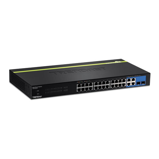
Page 10: Identifying External Components
Note: When the port was set to “Forced Mode”, the Auto MDI/MDIX IDENTIFYING EXTERNAL COMPONENTS will be disabled. This chapter describes the front panel, rear panel, and LED indicators of the Switch. Mini-GBIC slots (Port 25~26) The Switch is equipped with two combo mini-GBIC ports, supported Front Panel optional 1000BASE-SX/LX mini-GBIC module. -
Page 11: Understanding Led Indicators
UNDERSTANDING LED INDICATORS 100BASE-TX Port 1~24 Status LEDs Link/ACT: Link/Activity The front panel LEDs provides instant status feedback, and, helps monitor and troubleshoot when needed. : When the Link/ACT LED lights on, the respective port is successfully connected to an Ethernet network. Blinking : When the Link/ACT LED is blinking, the port is transmitting or receiving data on the Ethernet network. -
Page 12: 1000Base-T Port 27~28 Status Leds
When the respective port is connected to a 10Mbps Ethernet or 1000Mbps Gigabit Ethernet network. Follow the on-screen instructions to install the utility. Upon completion, go to Program Files TRENDnet Smart Switch Management Utility and open the Web Management utility. -
Page 13: Discovery List
System word definitions in the Discovery List: MAC Address: Shows the device MAC Address. IP Address: Shows the current IP address of the device. Protocol version: Shows the version of the Utility protocol. Product Name: Shows the device product name. System Name: Shows the appointed device system name. -
Page 14: Device Setting
“Set” to process the data changed Time, Device IP and the Event occurred. immediately. The default password of this TEG-424WS Gigabit Web The symbol “ ” represents the trap signal arise, this symbol will Smart Switch configuration is “admin”. -
Page 15: Toolbar
Toolbar The toolbar in the Web Management Utility have four main tabs, File, View, Options and Help. In the “File TAB”, there are Monitor Save, Monitor Save As, Monitor Password Change Load and Exit. Monitor Save: To record the setting of the Monitor List to the Firmware Upgrade: When the device has a new function, there will default, when you open the Web Management Utility next be a new firmware to update the device, use this function to update. -
Page 16: Configuring The Switch
IP Address, select the device shown in the Monitor List of the Web Management Utility to settle the The TEG-424WS Gigabit Web Smart Switch has a Web GUI interface device on the Web Browser. When the following dialog page for smart switch configuration. -
Page 17: Setup Setting
Speed: Setup Setting The 1~24 100BASE-TX port connections can operate in Forced Mode Find that there are seven items, including Port Setting, IEEE 802.1Q settings (100M Full, 100M Half, 10M Full, 10M Half), Auto, or VLAN Settings, Trunk Setting, Mirror Setting, IEEE 802.1p Default Disable. - Page 18 Untag VLAN Setting: Asymmetric VLAN The IEEE 802.1Q VLAN Configuration page provides powerful VID management functions. The original default VLAN setting has the IEEE 802.1Q Asymmetric VLAN default setting is “Disabled”, you VID as 01, named “default”, and contains all ports as “Untagged”. can press “Enabled”...
- Page 19 VID: A unique VLAN ID. PVID settings: VLAN Name: A VLAN name can be setting as user wish. While receiving an untagged frame from the port, the switch will assign a tag to the frame, using the PVID of the port as its VID. Port: The switch port number.
- Page 20 Step1: Set VLAN1 port 15~28 to “Not Member”, then apply setting. Example2: 802.1Q Asymmetric VLAN settings example: Port 1~28 in VLAN 1, port1~5 in VLAN 2, port1,6~9 in VLAN 3. All VLAN1~3 have access to Internet via port 1. Note: The multi-need server must be support IEEE 802.1Q VLAN Step1: Enable Asymmetric VLAN function.
- Page 21 Step 5: Set PVID Port 2~9 PVID value to below list: Step3: Create VID 02 and set port 1~5 to “Untag Port” member, then apply setting. Asymmetric VLAN’s PVID setting example Note: 1. Untag port VLAN member can exist in different VLAN groups simultaneously when Step4: Create VID 03 and set port 1, 6~9 to “Untag Port”...
- Page 22 Step1: Set VLAN1 port1 to “Tag Port” and port 15~28 to “Not Member”, then apply Tag VLAN Setting setting. The IEEE802.1Q protocol defines a new format of the frame; it adds a tag header in the original Ethernet frame, as follows: IEEE802.1Q Tag VLAN is divided by VLAN ID (VID).
-
Page 23: Trunk Setting
Example 4: Trunk Setting Setting Tag VLAN on two switches. Switch 1’s VLAN 1 (2 ~ 3 ports) The Trunking function enables the cascading of two or more ports for have access to the Switch 2’s VLAN 1 (2 ~ 3 ports). a combined larger bandwidth. -
Page 24: Mirror Setting
IEEE 802.1p Default Priority Mirror Setting This feature displays the status Quality of Service priority levels of Port Mirroring is a method of monitoring network traffic that forwards each port, and for packets that are untagged, the switch will assign the a copy of each incoming and/or outgoing packet from one port of the priority in the tag depending on your configuration. -
Page 25: Broadcast Storm Control Setting
Broadcast Storm Control Setting The Broadcast Storm Control feature provides the ability to control the receive rate of broadcasted packets. If Enabled (default is Disabled), threshold settings of 8,000 ~ 4,096,000 bytes per second can be assigned. Press Apply for the settings to take effect. IGMP Global Setting IGMP Snooping: Enable or Disable the IGMP Snooping function on Broadcast Storm Control Setting... -
Page 26: Igmp Vlan Setting
Robustness Variable (1-255): The Robustness Variable allows before above timer expires, the Leave message is dropped. Otherwise adjustment for the expected packet loss on a subnet. If a subnet is the Leave message is either forwarded to the port. Default is 1 second. expected to be lousy, the Robustness Variable may be increased. -
Page 27: System Setting
To view the Multicast Entry Table for a given VLAN, press the View System Setting button. Find that there are nine items, including System Information, System Setting, Trap Setting, Password Setting, Statistics, Factory Reset, Backup Setting, Firmware Upload and System Reboot in System menu. -
Page 28: System Setting
System Setting Trap Setting The System Setting includes IP Information and System information. By configuring the Trap Setting, it allows Web Management Utility to There are two ways for the switch to attain IP: Static and DHCP monitor specified events on this Web-Smart Switch. By default, Trap (Dynamic Host Configuration Protocol). -
Page 29: Password Setting
Clear Counter: To reset the details displayed. Password Setting To view the statistics of individual ports, click one of the Port ID as Setting a password is a invaluable tool for managers to secure the Web below. Smart Switch. After entering the old password and the new password two times, press Apply for the changes to take effect. -
Page 30: Backup Setting
Backup Setting System Reboot The backup setting help you to backup the current setting of the Provides to a safe way to reboot the system. Ensure the configuration Switch. Once you need to backup the setting, press the “Backup” has been saved, or all the changes you just made may be lost after button to save the setting. -
Page 31: Technical Specifications
TECHNICAL SPECIFICATIONS Performance Transmits General Store‐and‐forward Method: Standards IEEE 802.3 10BASE‐T Ethernet RAM Buffer: 128KBytes per device IEEE 802.3u 100BASE‐TX Fast Ethernet Filtering Address 8K entries per device IEEE 802.3ab 1000BASE‐T Gigabit Ethernet Table: IEEE 802.3z 1000BASE‐SX/LX Gigabit Ethernet MAC Address Automatic update Protocol CSMA/CD Learning: Data Transfer Ethernet: 10Mbps (half‐duplex), 20Mbps (full‐duplex) Packet Filtering / 10Mbps Ethernet: 14,880/pps Rate Fast Ethernet: 100Mbps (half‐duplex), 200Mbps (full‐duplex) Forwarding Rate: 100Mbps Fast Ethernet: 148,800/pps Gigabit Ethernet: 2000Mbps (full‐duplex) 1000Mbps Gigabit Ethernet: 1,488,000/pps Topology Star Network Cables 10BASET: 2‐pair UTP Cat. 3, 4, 5; up to 100m 100BASE‐TX: 2‐pair UTP Cat. 5; up to 100m 1000BASE‐T: 4‐pair UTP Cat. 5; up to 100m Fiber module: mini‐GBIC Fiber module Number of Ports 24 x 10/100M Auto‐MDIX Fast Ethernet ports ... -
Page 32: Limited Warranty
TEG-424WS - 5 Years Limited Warranty If a product does not operate as warranted above during the applicable warranty period, TRENDnet shall, at its option and expense, repair the TRENDNET SHALL NOT BE LIABLE UNDER THIS WARRANTY IF ITS TESTING AND EXAMINATION DISCLOSE THAT THE ALLEGED DEFECT IN defective product or deliver to customer an equivalent product to replace the THE PRODUCT DOES NOT EXIST OR WAS CAUSED BY CUSTOMER’S OR...
Need help?
Do you have a question about the TEG-424WS and is the answer not in the manual?
Questions and answers