Table of Contents
Advertisement
Advertisement
Table of Contents

Summary of Contents for BLX v100 positioner
-
Page 3: Table Of Contents
V100 Positioner CONTENTS 1 INTRODUCTION..........2 1.1 General ............ 2 1.2 Function ........... 2 1.3 Product Identification ....... 3 1.4 Air quality recommendations ....3 1.5 Safety Instructions ........4 2 INSTALLATION ..........5 2.1 Connections..........6 2.2 General mounting instructions ....6 2.2.1 Mounting on rotary actuators .... -
Page 4: Introduction
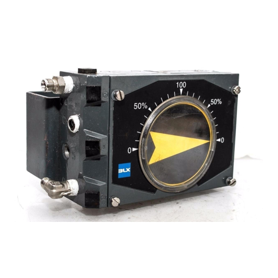
V100 Positioner Thank you for choosing the BLX V100 positioner 1. INTRODUCTION 1.1 General. BLX V100 is a compact, modular positioner for both BLX V100 corrosion resistant painting and sealing rotary and linear actuators, double or single acting. meet NEMA 4X as well as the sealing requirement IP 66. -
Page 5: Product Identification
The unit may completely fail. When the air cools in pipes etc. the moisture condenses and becomes liquid water. To ensure normal operational safety with BLX posit- Large quantities can build and sometimes flood ioner products, we recommend that a water separator small water separators. -
Page 6: Safety Instructions
V100 Positioner 1.5 Safety Instructions CAUTION: Beware of moving parts when positioner is operated! CAUTION: Beware of parts with live voltage! A voltage, which is normally not dangerous, is supplied to the positioner. Avoid touching live parts and bare wires as well as short circuting live parts and the housing. -
Page 7: Installation
V100 Positioner 2. INSTALLATION 2.1 Connections S – Supply air V100P: max. 145 PSI / 1 MPa V100E: 23 - 145 PSI / 0,15 -1 MPa – Input, pressure signal V100P: 3-15 PSI / 20-100 kPa V100E: Plugged – Input, current signal... -
Page 8: General Mounting Instructions
The V100 has the ISO F05 hole pattern(1) for mounting kits. 2.2.1 Rotary actuator The BLX V100 has a very stable and pro- perly sized drive shaft bearing. However, the positioner drive(A) should be aligned properly to the rotary actuator spindle(B). -
Page 9: Installation Instructions For Rotary Actuators
V100 Positioner 2.3 Installation instructions for rotary actuators Direct (CCW) 2.3.1 Double acting Signal opens Reverse (CW) Signal closes 2.3.2 Single acting Reverse (CW) Direct (CCW) Spring opens Spring closes Signal closes Signal opens Direct (CCW) Reverse (CW) Spring opens... -
Page 10: Installation Instructions For Linear Actuators
V100 Positioner 2.4 Installation instructions for linear actuators 2.4.1 Double acting Direct (CCW) Signal closes Signal opens Reverse (CW) Signal opens Signal closes 2.4.2 Single acting Spring opens Spring closes Direct (CCW) Signal closes Signal opens Spring opens Spring closes... -
Page 11: Cam
V100 Positioner 2.5 Cam The V100 is standard shipped with the C1-cam, factory set for 90° , direct (CCW) turning. ±1° 2.5.1 Adjustments Remove the front cover and indicator. (see page 12) 1. Loosen the lock screw(1) and the cam nut(2). -
Page 12: Ma Connection
V100 Positioner 2.6 4-20 mA connection 2.6.1 Connecting the control signal Remove the front cover and indicator. (see page 12) Loosen the screw(1) enough so that the connection card can be lifted. Secure the connection card into the small slot(2). -
Page 13: Calibration
V100 Positioner 2.7 Calibration The V100 is delivered factory calibrated 0-100 % ±1%. Calibration procedure Zero position 1. Set 0% input signal. 2. Wait until the valve has adjusted. 3. Adjust the zero position by turning the zeroing screw(3), with a screw- driver from the outside or by using a slot(3a) on the yellow wheel. -
Page 14: Maintenance
V100 Positioner 3. MAINTENANCE 3.1 Front cover and Indicator Removing the front cover Remove the four screws(1) and the front cover. Changing the sealing in the front cover Remove the indicator cover(2) by pressing from the backside.(see sketch) Remove the rubber gasket(3) and replace with a new gasket. -
Page 15: Pilot Valve
V100 Positioner 3.2 Pilot valve Removal Remove the front cover and indicator. (see page 12) Loosen the pilot retaining screw(1). Lift the pilot valve(2) straight up. Cleaning Remove the spool(3) from the valve housing. Clean the parts with a soft cloth and ;;;;... -
Page 16: I/P-Converter, Type Ea1
V100 Positioner 3.3 I/P-converter, type E1A Cleaning the restrictor nozzle The nozzle(1) can be removed for cleaning with the supply air on. Use caution when removing the nozzle in that the air pressure may cause the nozzle to ”shoot out” from the unit. -
Page 17: Filter
V100 Positioner 3.4 Filter Changing the filter 1. Remove the front cover and indicator. (See page 12) 2. Loosen the screw(1) and lift out the card. 3. Loosen the screws(3) and lift out the I/P-converter. 4. Loosen the screws(5) and remove the membrane cover(6). -
Page 18: Membrane
V100 Positioner 3.5 Membrane Removal Loosen the screws(1) and remove the membrane cover(2). Be cautious of the O-ring in the membrane cover. Loosen the screw(3). Remove the washer(4), membrane(5) and membrane piston(6). Mounting the membrane Install the membrane piston(6) over the cylindrical dowel(7). -
Page 19: Feedback Spring, Changing
V100 Positioner 3.6 Feedback spring, changing Removal The feedback spring(1) can be removed by inserting a screwdriver between the upper spring coils and compressing it so that the upper spring socket is released from its seat. Mounting Before the feedback spring is replaced, a basic adjustment must be performed. -
Page 20: Feed Back Spring, Disassembly
V100 Positioner 3.7 Feedback spring Disassembling A.Remove the spring support(1) from the red range nut(3). B.Disassemble the spring support(1) and the spring(4). C.Hold the spring socket(5) and try to push the spring off the socket by pressing a screwdriver or similar against the end of the spring. -
Page 21: Balance Arm
V100 Positioner 3.8 Balance arm Removal Before the balance arm can be remov- ed, the front cover(1), I/P-converter or cover(2), membrane cover(3), memb- rane(4), feedback spring(5) and pilot valve(6) must all be removed. Loosen the screws(7) and remove the balance arm(8). -
Page 22: Guide Arm, Changing
V100 Positioner 3.9 Guide arm, changing Removal Before the guide arm can be removed, the feedback spring (see page 17) and cam (see page 9) has to be removed. Remove the stop washer(1). Loosen the screws(2) and remove the arm(3) together with the guide pin(4) and spring(5). -
Page 23: Guide Arm, Disassembly
V100 Positioner 3.10 Guide arm, disassembly Ball bearing, changing Loosen the screw(1) and remove the ball bearing. Mount the new ball bearing with Loctite in the M4-hole on the arm and tighten the screw securely. Zeroing screw, removal. Loosen the socket set screw(2). -
Page 24: Drive Shaft
V100 Positioner 3.11 Drive shaft Removal Before the drive shaft can be loosened, the cam must be removed. Remove the drive shaft(1) by hand from the inside. If necessary replace defective O-rings(2 & 3). Mounting Apply a small amount of oil to the drive shaft’s surface and O-rings. -
Page 25: Drive
V100 Positioner 3.12 Drive BLX offers a variety of drives(1), suitable for the most frequently used actuator types. Removal “Pop out” the drive by prying two screwdrivers, equally under the edges(2) of the drive, using the housing as fulcrum. Mounting Press the drive down into the drive shaft hole. -
Page 26: Safety Valve
V100 Positioner 3.13 Safety valve Removal Loosen the screws(1). Remove the tightening cover(2) and the gasket(3). Lift out the safety valve(6). Safety valve, assembly The safety valve is designed with a weak spring(4) and a rubber plug(5). For proper functioning, the spring and the rubber plug need to be mounted together. -
Page 27: Converting
V100 Positioner 4. CONVERTING 4.1 Converting from V100P to V100E 1. Remove the front cover and indicator. (see page 12) 2. Loosen the screws(1) and remove the cover(2). 3. Unscrew the protective plug from the -connection(8). Please Note! Check the seals(3 & 4). -
Page 28: Spare Parts
V100 Positioner 5. SPARE PARTS 5.1 Exploded drawing... -
Page 29: Spare Parts List
V100 Positioner 5.2 Spare parts list Item Description Part no 1 ..Membrane cover ......... 10066 ..... Screw MCS 5x14-5 SS ........- Mylar washer ........10095 ..... - O-ring Ø 5x2 NBR .......... 2 ..Cover plate .......... 10061 ..... -
Page 30: Technical Info
V100 Positioner 6. TECHNICAL INFO 6.1 Specifications V100P V100E nput range: 3-15 PSI (20-100kPa) 4-20 mA (Ri<250ohms) Supply pressure: <145 PSI (<1MPa) 21.8-145 PSI (0.15-1MPa) Linearity error: <0.7% f.s <1.0% f.s Hysteresis: <0.4% f.s <0.6% f.s Repeatability: <0.3% f.s <0.5% f.s... -
Page 31: Dimensions
V100 Positioner 6.2 Dimensions...
Need help?
Do you have a question about the v100 positioner and is the answer not in the manual?
Questions and answers