Table of Contents
Advertisement
CONTENTS
SAFETY CONSIDERATIONS . . . . . . . . . . . . . . . . . . . . .1,2
INSTALLATION . . . . . . . . . . . . . . . . . . . . . . . . . . . . . . . . 2-36
Step 1 - Provide Unit Support . . . . . . . . . . . . . . . . . . . 2
Step 2 - Rig and Place Unit . . . . . . . . . . . . . . . . . . . . . 2
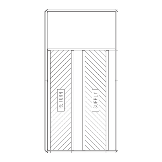
• POSITIONING
Step 3 - Field Fabricate Ductwork . . . . . . . . . . . . . . . 2
Step 4 - Make Unit Duct Connections . . . . . . . . . . . 2
Step 5 - Install Flue Hood . . . . . . . . . . . . . . . . . . . . . . 17
Step 6 - Trap Condensate Drain . . . . . . . . . . . . . . . . 17
Step 7 - Install Gas Piping . . . . . . . . . . . . . . . . . . . . . 18
Step 8 - Make Electrical Connections . . . . . . . . . . 18
Adjustments . . . . . . . . . . . . . . . . . . . . . . . . . . . . . . . . . . 30
Relief Damper Hood. . . . . . . . . . . . . . . . . . . . . . . . . . . 30
Step 12 - Install All Accessories . . . . . . . . . . . . . . . 30
Step 13 - Perform Field Modifications . . . . . . . . . . 33
BACnet Communication Option Wiring . . . . . . . . . 33
SAFETY CONSIDERATIONS
Installation and servicing of air-conditioning equipment can
be hazardous due to system pressure and electrical compo-
nents. Only trained and qualified service personnel should in-
stall, repair, or service air-conditioning equipment.
Untrained personnel can perform the basic maintenance
functions of cleaning coils and filters and replacing filters. All
other operations should be performed by trained service per-
sonnel. When working on air-conditioning equipment, observe
precautions in the literature, tags and labels attached to the unit,
and other safety precautions that may apply.
Follow all safety codes. Wear safety glasses and work
gloves. Use quenching cloth for unbrazing operations. Have
fire extinguishers available for all brazing operations.
WARNING
Before performing service or maintenance operations on
unit, turn off main power switch to unit. Electrical shock
could cause personal injury.
Manufacturer reserves the right to discontinue, or change at any time, specifications or designs without notice and without incurring obligations.
Catalog No. 04-53480095-01
Single Package Gas Heating/Electric Cooling
Rooftop Units with ComfortLink Controls
Installation Instructions
Page
Printed in U.S.A.
48A2,A3,A4,A5020-060
and PURON
®
1. Improper installation, adjustment, alteration, service,
or maintenance can cause property damage, personal
injury, or loss of life. Refer to the User's Information
Manual provided with this unit for more details.
2. Do not store or use gasoline or other flammable va-
pors and liquids in the vicinity of this or any other
appliance.
What to do if you smell gas:
1. DO NOT try to light any appliance.
2. DO NOT touch any electrical switch, or use any
phone in your building.
3. IMMEDIATELY call your gas supplier from a neigh-
bor's phone. Follow the gas supplier's instructions.
4. If you cannot reach your gas supplier, call the fire
department.
DO NOT USE TORCH to remove any component. System
contains oil and refrigerant under pressure.
To remove a component, wear protective gloves and gog-
gles and proceed as follows:
a. Shut off electrical power to unit.
b. Recover refrigerant to relieve all pressure from sys-
tem using both high-pressure and low pressure ports.
c. Traces of vapor should be displaced with nitrogen
and the work area should be well ventilated. Refrig-
erant in contact with an open flame produces toxic
gases.
d. Cut component connection tubing with tubing cutter
and remove component from unit. Use a pan to catch
any oil that may come out of the lines and as a gage
for how much oil to add to the system.
e. Carefully unsweat remaining tubing stubs when nec-
essary. Oil can ignite when exposed to torch flame.
Failure to follow these procedures may result in personal
injury or death.
DO NOT re-use compressor oil or any oil that has been
exposed to the atmosphere. Dispose of oil per local codes
and regulations. DO NOT leave refrigerant system open to
air any longer than the actual time required to service the
equipment. Seal circuits being serviced and charge with
dry nitrogen to prevent oil contamination when timely
repairs cannot be completed. Failure to follow these proce-
dures may result in damage to equipment.
Form 48A-12SI
Pg 1
WEATHERMAKER
Refrigerant (R-410A)
WARNING
WARNING
CAUTION
7-13
Replaces: 48A-10SI
®
Advertisement
Table of Contents

Related Manuals for Carrier WEATHERMAKER 48A2


Summary of Contents for Carrier WEATHERMAKER 48A2
-
Page 1: Table Of Contents
WEATHERMAKER ® 48A2,A3,A4,A5020-060 Single Package Gas Heating/Electric Cooling Rooftop Units with ComfortLink Controls and PURON ® Refrigerant (R-410A) Installation Instructions CONTENTS WARNING Page SAFETY CONSIDERATIONS .....1,2 1. -
Page 2: Installation
NOTE: On retrofit jobs, ductwork may be attached to the old unit instead of a roof curb. Be careful not to damage ductwork WARNING when removing old unit. Attach existing ductwork to roof curb instead of unit. Disconnect gas piping from unit when pressure testing at pressure greater than 0.5 psig. - Page 3 a48-6715...
- Page 4 a48-6716...
- Page 5 a48-6717...
- Page 6 a48-8687...
- Page 7 A48-8689...
- Page 8 a48-8691...
- Page 9 A48-8686...
- Page 10 a48-8688...
- Page 12 a48-8690...
- Page 13 Table 1 — Physical Data — 48A2,A3,A4,A5 Units UNIT 48A2,A3,A4,A5 020D/E 025D/E 027D/E 030D/E NOMINAL CAPACITY (tons) BASE UNIT See Unit Weights Table OPERATING WEIGHT (lb) COMPRESSOR Quantity ... Type (Ckt 1/Ckt 2) 2 ... ZP67/1…ZP91 2 ... ZP91/1…ZP91 2 ... ZP91/1…ZP91 2…ZP72, 2…ZP72 Number of Refrigerant Circuits Precharged...
- Page 14 Table 1 — Physical Data — 48A2,A3,A4,A5 Units (cont) UNIT 48A2,A3,A4,A5 035D/E 040D/E 050D/E 060D/E NOMINAL CAPACITY (tons) BASE UNIT See Unit Weights Table OPERATING WEIGHT (lb) COMPRESSOR Quantity ... Type (Ckt 1/Ckt 2) 2 ... ZP67/2…ZP103 2…ZP103/2…ZP103 2…ZP120/2…ZP120 2…ZP154/2…ZP154 Number of Refrigerant Circuits Precharged Precharged...
- Page 15 a48-8369...
- Page 16 Table 2 — Unit Operating Weights (lb) UNIT SIZE 48A2D,A3D 3825 3961 3961 3992 4340 4770 4914 7066 48A2E,A3E 3905 4041 4041 4072 4500 4930 5074 7306 48A4D,A5D 3865 4001 4001 4032 4380 4810 4954 7106 48A4E,A5E 3945 4081 4081 4112 4540 4970...
-
Page 17: Step 5 - Install Flue Hood
Table 6 — Evaporator Fan Motor Data MOTOR UNIT MOTOR MOTOR SHEAVE BUSHING SHEAVE BUSHING BELT BELT SIZE MOTOR SHAFT SHAFT DIA. SHEAVE PITCH DIAMETER SHEAVE PITCH DIAMETER (Quantity) TENSION 48A2,A3, SPEED (in.) (P/N) DIAMETER (in.) (P/N) DIAMETER (in.) (P/N) (lb at .25 in.) A4,A5 (rpm) -
Page 18: Step 7 - Install Gas Piping
Step 7 — Install Gas Piping — Unit is equipped for GAS SECTION use with natural gas. Installation must conform with local ACCESS PANEL building codes or, in the absence of local codes, with the Na- FLUE HOOD tional Fuel Gas Code, ANSI Z223.1. Install manual gas shutoff valve with a -in. -
Page 19: Field Power Supply
(sizes 040-060) knockouts for the field power wiring. See Fig. 4-9. If control wiring is to be brought in through the side of unit, a -in. diameter hole is provided in the condenser side post next to the control box. Do not route control wiring in the same conduit as power wiring. - Page 20 Table 8A — Electrical Data — 48A2,A3,A4,A5020-060 Units without Convenience Outlet COMPRESSOR VOLTAGE CONDENSER EVAPORATOR POWER UNIT EXHAUST POWER SUPPLY VOLTAGE RANGE FAN MOTOR FAN MOTOR SIZE Cir A, No. 1 Cir A, No. 2 Cir B, No. 1 Cir B, No. 2 3 PH, 60 Hz Min Max RLA LRA RLA LRA RLA LRA RLA LRA FLA (total)
- Page 21 Table 8A — Electrical Data — 48A2,A3,A4,A5020-060 Units without Convenience Outlet (cont) COMPRESSOR VOLTAGE CONDENSER EVAPORATOR POWER UNIT EXHAUST POWER SUPPLY VOLTAGE RANGE FAN MOTOR FAN MOTOR SIZE Cir A, No. 1 Cir A, No. 2 Cir B, No. 1 Cir B, No. 2 3 PH, 60 Hz Min Max RLA LRA RLA LRA RLA LRA RLA LRA FLA (total)
- Page 22 Table 8A — Electrical Data — 48A2,A3,A4,A5020-060 Units without Convenience Outlet (cont) COMPRESSOR VOLTAGE CONDENSER EVAPORATOR POWER UNIT EXHAUST POWER SUPPLY VOLTAGE RANGE FAN MOTOR FAN MOTOR SIZE Cir A, No. 1 Cir A, No. 2 Cir B, No. 1 Cir B, No. 2 3 PH, 60 Hz Min Max RLA LRA RLA LRA RLA LRA RLA LRA FLA (total)
- Page 23 Table 8A — Electrical Data — 48A2,A3,A4,A5020-060 Units without Convenience Outlet (cont) VOLTAGE COMPRESSOR CONDENSER EVAPORATOR POWER UNIT VOLTAGE POWER SUPPLY SIZE RANGE Cir A, No. 1 Cir A, No. 2 Cir B, No. 1 Cir B, No. 2 FAN MOTOR FAN MOTOR EXHAUST 3 PH, 60 Hz...
- Page 24 Table 8B — Electrical Data — 48A2,A3,A4,A5020-060 Units with Convenience Outlet COMPRESSOR VOLTAGE CONDENSER EVAPORATOR POWER CONVENIENCE POWER SUPPLY UNIT RANGE FAN MOTOR FAN MOTOR EXHAUST OUTLET VOLTAGE Cir A, No. 1 Cir A, No. 2 Cir B, No. 1 Cir B, No. 2 SIZE 3 PH, 60 Hz Min Max RLA LRA RLA LRA RLA LRA RLA LRA...
- Page 25 Table 8B — Electrical Data — 48A2,A3,A4,A5020-060 Units with Convenience Outlet (cont) COMPRESSOR VOLTAGE CONDENSER EVAPORATOR POWER CONVENIENCE POWER SUPPLY UNIT RANGE FAN MOTOR FAN MOTOR EXHAUST OUTLET VOLTAGE Cir A, No. 1 Cir A, No. 2 Cir B, No. 1 Cir B, No. 2 SIZE 3 PH, 60 Hz Min Max RLA LRA RLA LRA RLA LRA RLA LRA...
- Page 26 Table 8B — Electrical Data — 48A2,A3,A4,A5020-060 Units with Convenience Outlet (cont) COMPRESSOR VOLTAGE CONDENSER EVAPORATOR POWER CONVENIENCE POWER SUPPLY UNIT VOLTAGE RANGE FAN MOTOR FAN MOTOR EXHAUST OUTLET Cir A, No. 1 Cir A, No. 2 Cir B, No. 1 Cir B, No. 2 SIZE 3 PH, 60 Min Max RLA LRA RLA LRA RLA LRA RLA LRA...
-
Page 27: Field Control Wiring
® (variable volume Bring low-voltage control wiring through the -in. diame- variable temperature) or Carrier TEMP system control ter hole provided in the condenser section side post. Use strain operation. relief going into -in. diameter hole in bottom of unit control •... - Page 28 2 of the 3-pin plug. c. Insert and secure the black (–) wire to terminal 3 of T58 Communicating Thermostat — Carrier also has a fully the 3-pin plug. communicating thermostat which, if used, will be wired to the 4.
- Page 29 Remote IAQ Override — If the control is being used with non interface to fire and smoke control systems and allows for the Carrier building management system it supports the use of the following system overrides from remote switch inputs.
-
Page 30: Step 9 - Make Outdoor-Air Inlet
Step 9 — Make Outdoor-Air Inlet Adjustments 16. Slide two 20 x 25-in. filters into cross members of hood assembly. Attach filter cover over filters with screws and ECONOMIZER FIXED OUTDOOR speed clips provided. DAMPER — Hoods are used on all units with economizer or adjustable self-closing fixed outdoor air damper. - Page 31 HOOD TOP FLANGE BLACK HOOD SIDE SEAL STRIP HOOD SIDE 48-1104 Fig. 26 — Adding Seal Strip to Back of Hood Top Mounting Flange Fig. 23 — Adding Seal Strip to Top of Hood Sides GRAY FOAM STRIP CROSS MEMBER 48-1105 Fig.
- Page 32 Instructions are shipped with each accessory. Configuration of system with the Carrier Comfort Network ® [CCN] the controls for these accessories as well as the factory-installed...
-
Page 33: Step 13 - Perform Field Modifications
a48-3808 NOTES: 1. Unless otherwise specified, all dimensions are to outside of part. 2. Dimensions are in inches. 3. On 48A4,A5 units, accessory barometric relief or power exhaust must be mounted in the field-supplied return ductwork. Fig. 32 — Barometric Relief Damper and Power Exhaust Mounting Details barometric relief cannot be used because of return air ductwork will cover the power exhaust or barometric relief installation locations. - Page 34 97.78” (027-050), 150.47” (060) INSIDE DIMENSION 31.25” INSIDE a48-8371 Fig. 34 — Side Return Air Conversion Wire the controllers on an MS/TP network segment in a dai- 5. Verify communication with the network by viewing a sy-chain configuration. Wire specifications for the cable are module status report.
- Page 35 Table 12 — MS/TP Wiring Recommendations SPECIFICATION RECOMMMENDATION Cable Single twisted pair, low capacitance, CL2P, 22 AWG (7x30), TC foam FEP, plenum rated cable Conductor 22 or 24 AWG stranded copper (tin plated) Insulation Foamed FEP 0.015 in. (0.381 mm) wall 0.060 in. (1.524 mm) O.D. Color Code Black/White Twist Lay...
-
Page 36: Installation
Fig. 36 — Open System Network Wiring Fig. 37 — BT485 Terminator Installation © Carrier Corporation 2013 Manufacturer reserves the right to discontinue, or change at any time, specifications or designs without notice and without incurring obligations. Catalog No. 04-53480095-01 Printed in U.S.A.
Need help?
Do you have a question about the WEATHERMAKER 48A2 and is the answer not in the manual?
Questions and answers