Table of Contents
Advertisement
All rights are reserved by KIMESSA. Any reproduction, whether in hard or digital copy, even in part, without
written permission of KIMESSA-Swiss in any design and shape is prohibited.
The information in the documents are created according to current knowledge. Due to ongoing product deve-
KIMESSA AG
Rautistrasse 12
CH-8047 Zurich / Switzerland
Copyright © 2014 by KIMESSA –Switzerland
Operating Instructions
Alarm and Control system
right © 2015 by KIMESSA –Switzerland
lopments, technical changes or deviations may occur.
CANline 02
Tel.:
Fax: +41 (0)44 404 38 39
Email info@kimessa.com
Home www.kimessa.com
Page 1
+41 (0)44 404 38 38
CANline 02 Operating instructions 16.04.15hs/mb
Copy
py-
Advertisement
Table of Contents

Related Manuals for Kimessa CANline 02


Summary of Contents for Kimessa CANline 02
-
Page 1: Operating Instructions
Copy right © 2015 by KIMESSA –Switzerland All rights are reserved by KIMESSA. Any reproduction, whether in hard or digital copy, even in part, without written permission of KIMESSA-Swiss in any design and shape is prohibited. The information in the documents are created according to current knowledge. Due to ongoing product deve- lopments, technical changes or deviations may occur. -
Page 2: Table Of Contents
ELECTRICIANS AND MAINTENANCE TECHNICIANS PERSONAL PROTECTIVE EQUIPMENT 2 USAGE ..........................12 2.1 I .................................. 12 NTRODUCTION 3 CANLINE 02 CONSTRUCTION ................... 13 4 INSTALLATION ........................14 4.1 C ? ...... 14 ONDITIONS OF USE NSTALLATION HERE AND HOW WILL THE CONTROL UNIT BE MOUNTED 4.2 M... - Page 3 10.8 „T “ ..............................47 IMERS 10.9 „F “ ................................48 10.10 „P “ (P ) ......................49 RINT ETTINGS ROTOCOL 10.11 „S “ ..............................49 ERVICE Copyright © 2015 by KIMESSA –Switzerland Page 3/63 CANline 02 Operating instructions 28.07.15mb...
- Page 4 14 MAINTENANCE / REPAIR ....................58 14.1 M ..........................60 AINTENANCE ERVICE DISPLAY 14.2 M ..............................60 AINTENANCE CYCLE 15 FAULTS, CAUSES AND SOLUTIONS ................. 62 16 DECLARATION OF CONFORMITY ..................63 Copyright © 2015 by KIMESSA –Switzerland Page 4/63 CANline 02 Operating instructions 28.07.15mb...
-
Page 5: General Information
This applies both for property and for personal injury of any kind. KIMESSA disclaims any liability for any advice and execution errors by personnel which are not permanent employees of KIMESSA. Even if the dealer is acting on behalf of the company, they shall be liable for their own actions. -
Page 6: Warranty
1.4 Warranty KIMESSA AG guarantees the quality of all its products. It grants a guarantee on the material, under normal use and regular maintenance, for 12 months from the date of purchase. A later commissioning of the products does not extend the guarantee period, since for example sensors age due to storage conditions. KIMESSA shall re- pair or replace free of charge any part which proves to be defective within the warranty period. -
Page 7: Risk / Potential Hazard
1.8 Risk / Potential hazard KIMESSA gas detection systems and transmitters pose no risks subject to a proper and appropriate. use of our systems and components, these represent no hazard. A threat of non-execution or false alarm is only given when untrained and unauthorized personnel operate the gas detection system, transmitters and input signals. - Page 8 During installation and operation of the equipment, it must be ensured that no electrostatic • charges (no high flow rate; cleaning with a damp cloth, etc.) occur on the plastic parts (type label, plastic housing). Copyright © 2015 by KIMESSA –Switzerland Page 8/63 CANline 02 Operating instructions 28.07.15mb...
-
Page 9: Definition Of The Signal Words
Please note the regulations concerning the transport and storage of gas bottles. Gas detection systems are used for protection of persons and property and may be retrieved or serviced only by trained personnel. A product training and authorisation by KIMESSA is com- pulsory. - Page 10 If at the CANline 02 so-called ex-sensor is to be connected, it must meet the requirements for testing personnel (explosion protection) Tester Training Experience Timely action ü Instruction ü Usage; application ü regular use "Trained" ü Desired condition ü Annual training Person ü...
-
Page 11: E Lectrical Installation
PSA is not necessary Disposal Employee represen- the appropriate collection is per- None tatives formed according to EU Directive (2002/96 / EC) Copyright © 2015 by KIMESSA –Switzerland Page 11/63 CANline 02 Operating instructions 28.07.15mb... -
Page 12: Usage
3 alarm thresholds per measuring point and can be split into 2 fire/ventilation zones or groups. The CANline 02 control unit also has an alarm for over- and undershooting the measurement signal, with which relevant relays can be programmed that then, for example, visualize a fault accordingly. -
Page 13: Canline 02 Construction
3 CANline 02 Construction The CANline 02 consists of a lower part and an upper part, plastic, grey, RAL 7035. The lower part comes with mounting holes and carries the cable relief and cable glands for the connection cable between the sensor and the power supply. -
Page 14: Installation
The cable glands are mounted on the lower part of the CANline 02 housing, facing downwards. It is important to ensure that the gas detection control unit is always accessible. Note that the upper part of housing opens upwards for wiring, programming and during maintenance work. -
Page 15: Mechanical Installation Of Can Line 02
After installation, attach the upper part again (plastic brackets). Close the control unit and check the fit: If the back panel is properly installed, the control unit closes easily. Copyright © 2015 by KIMESSA –Switzerland Page 15/63 CANline 02 Operating instructions 28.07.15mb... -
Page 16: Delivery Contents, Canline 02 Gas Detection Control Unit
4.3 Delivery contents, CANline 02 gas detection control unit 4.4 CANline/opening/closing the control unit D = 212 mm L = 230 mm Fig. 1 Installation hole 4.5 Installation measurements E = 84 mm H = 90 mm W = 130 mm 26.5 mm... -
Page 17: T2 Amp Fuses
In each case, the cable cross section must be calculated. The length of the + wire and the −wire and the total power consumption must be taken into consideration Copyright © 2015 by KIMESSA –Switzerland Page 17/63 CANline 02 Operating instructions 28.07.15mb... -
Page 18: Kimessa-Cable
The insulation and sheath are made of a special plastic (LSZH) which prevents halogen gases from being emitted in the case of a fire. KIMESSA electronics cables are therefore suitable for installation in public buildings (hospitals, theaters, etc. ). The good protection by the shield of a thin and effective copper braid allows for interference-free signal and impulse transfer. - Page 19 16 Volt at the end of the cable is just enough; less than a 16 VDC supply is too small for the CO sensor. Copyright © 2015 by KIMESSA –Switzerland Page 19/63 CANline 02 Operating instructions 28.07.15mb...
-
Page 20: Electrical Installation/Emc And Atex
(the size depends on the type of Rosette made of braided screw joint). shield Gland body and nut must be tightened with a torque of 20 Nm Copyright © 2015 by KIMESSA –Switzerland Page 20/63 CANline 02 Operating instructions 28.07.15mb... - Page 21 - ?-wired standard cable with shield - Conductor cross-section: 1 mm2 - Cable diameter 7.1 mm, KIMESSA special cable Running cable • - If risk of mechanical damage is possible, the cable must be appropriately protected (protective tube, etc.)
- Page 22 - Check whether the device is ready for operation ü The parameterization for this application must be carried out ü All interfaces such as inputs and outputs for control purposes must be connected and ready. Copyright © 2015 by KIMESSA –Switzerland Page 22/63 CANline 02 Operating instructions 28.07.15mb...
-
Page 23: Canline 02 Connections
(Analogue) connection 1 Fig. 4 CANLine 02-connection-board Connection Bus-line Connection Reset (exter- connection 2 Sensor 3 and 4 nal, digital) (Analogue) 230 VAC "inactive" power connec- tion Copyright © 2015 by KIMESSA –Switzerland Page 23/63 CANline 02 Operating instructions 28.07.15mb... -
Page 24: Wiring Schematic For 2 X 4
5.1 Wiring Schematic for 2 x 4..20mA detectors 5.2 Wiring Schematic for 2 x digital BUS detectors Copyright © 2015 by KIMESSA –Switzerland Page 24/63 CANline 02 Operating instructions 28.07.15mb... -
Page 25: Wiring Schematic For Realy Contacst
5.3 Wiring Schematic for realy contacst (standard) Copyright © 2015 by KIMESSA –Switzerland Page 25/63 CANline 02 Operating instructions 28.07.15mb... -
Page 26: User Comfort
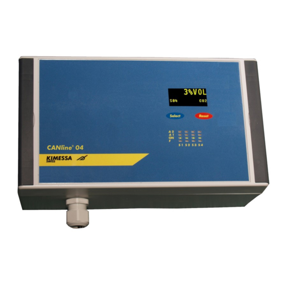
6 User comfort 6.1 Front view, dimensions and control elements Dimensions: Height Width Depth Weight 1.10 6.2 Front functions Copyright © 2015 by KIMESSA –Switzerland Page 26/63 CANline 02 Operating instructions 28.07.15mb... -
Page 27: Alarm Reset
With the appropriate programming of the CANline 02 control unit, in the event of an alarm, the acoustic alarm (signal horn) can be turned off by pressing the "RESET button" or by remote reset. -
Page 28: Switching On
Fig. 6 CANline02 System Start Fig 1 TEST As seen on the display (right), the menu can be accessed by using the buttons. Fig. 7CANline Systemstart 2 Copyright © 2015 by KIMESSA –Switzerland Page 28/63 CANline 02 Operating instructions 28.07.15mb... -
Page 29: Main Menu
- Sensor 1 and Sensor 2 - Relay 1 - Relay 5 are only in the visible variation, which allows for programming the CANline 02 control unit via the buttons. Programming via the buttons is described on page 47. Copyright © 2015 by KIMESSA –Switzerland Page 29/63 CANline 02 Operating instructions 28.07.15mb... -
Page 30: Normal Operation / Sensor Display
Menu, the respective menu item is high- lighted in yellow, and the buttons Previous "<" ; "Ok" and forward ">" are visible in the display Fig. 9 Manual programming Copyright © 2015 by KIMESSA –Switzerland Page 30/63 CANline 02 Operating instructions 28.07.15mb... -
Page 31: System Info Menu
"Service Message Service Reset Now," whereby the display of the message returns to "System Info Next Service" in the menu without changing the setting of the interval. Copyright © 2015 by KIMESSA –Switzerland Page 31/63 CANline 02 Operating instructions 28.07.15mb... -
Page 32: Quantity Of Sensors - System Info
Return to "normal operation" by pressing the ">" button or "<" button until you reach "Exit": "OK" button; for "System Info," with ">" button or "<" button until you reach "Exit": "OK" button: for "Normal operation" Copyright © 2015 by KIMESSA –Switzerland Page 32/63 CANline 02 Operating instructions 28.07.15mb... -
Page 33: Dc Voltage Info - System Power
Return to "normal operation" by pressing the ">" button or "<" button until you reach "Exit": "OK" button; for "System Info," with ">" button or "<" button until you reach "Exit": "OK" button: for "Normal operation," Copyright © 2015 by KIMESSA –Switzerland Page 33/63 CANline 02 Operating instructions 28.07.15mb... -
Page 34: Alarm History 1 ... 10 - S Ensor 3 Alarm - History 2 - System Info
"Alarm History 1 ... 10" and then the ">" button or the "<" button to" Exit ": "OK" button; for "System Info," with ">" button or "<" button until you reach "Exit": "OK" button: for "Normal operation" Copyright © 2015 by KIMESSA –Switzerland Page 34/63... -
Page 35: Relay Check 1 ... 5 / M Enu Structure / System Info
Return to "normal operation" with the "OK" button; for "Relay check," "<" button or "<" button unto "Exit": "OK" button; for "Relay Check 1 ... 5,": "> Button" or "<button" until "Exit" "OK" button: for "Normal operati- on" Copyright © 2015 by KIMESSA –Switzerland Page 35/63 CANline 02 Operating instructions 28.07.15mb... -
Page 36: Exit To Main Menu
Fig. 11 exit to the main menu / input Likewise, by using the button functions ">", "OK / SELECT" and ">" buttons you can return to the main menu. Copyright © 2015 by KIMESSA –Switzerland Page 36/63 CANline 02 Operating instructions 28.07.15mb... -
Page 37: Exit To "Normal Operation
8.13 "Normal operation" via "Exit" in the main menu Likewise, by using the button functions ">", "OK / SELECT" and ">" buttons you can return to the main menu. Copyright © 2015 by KIMESSA –Switzerland Page 37/63 CANline 02 Operating instructions 28.07.15mb... -
Page 38: Commissioning
Caution! Set the jumper for the bus termination resistor correctly (see also section "Bus-end resistance”) Connect Central with the PC - Startup Tools - canLine Copyright © 2015 by KIMESSA –Switzerland Page 38/63 CANline 02 Operating instructions 28.07.15mb... -
Page 39: Programming By Software
The suitable software CANlineCMConfigurator and the necessary USB-Driver is available from KIMESSA info@kimessa.com To program the monitor, connect the USB-Cable (available from KIMESSA) to the P3-Connector on the CPU-Board. The black USB- Cable must be connected to the white arrow beside P3 Copyright ©... -
Page 40: Start
(Typically in the menu „Programs“ – Kimessa) 10.2 Menu-Item „Firmware“ To program a CANline 02 or a CANline 04 by the CANline CM Configurator, you have to start with a Firmware-Update to overwrite the Factory-Firmware, which is designed for Button programming. - Page 41 Firmware* for Soft- ware-Configuration you want to update *CM_PC-FIRMWARE_XXX.bin 3. Press “Download” à after approx. 1. minute the CANline will restart again and you can start programming Copyright © 2015 by KIMESSA –Switzerland Page 41/63 CANline 02 Operating instructions 28.07.15mb...
-
Page 42: Start: Import Data From Canline
3. As as soon as you hear a „beep“ sound the download has been completed If you have started with a Firmware-Upgrade on a CANline 02/04 (point 10.2), don't start with „receive“, because the montor has no settings file. Use instead “File” -> „Open“ and open the *.bin settings file (provided by KIMESSA) and press „Transmit“... -
Page 43: Menu-Item „Settings
(Factory Default: 60 seconds) in days, until message „Service Now“ occurs. After maintenance, Service Interval: this message will be reset by service staff, authorized by Kimessa or agents of Kimessa only (see point “Servicemessage) Copyright © 2015 by KIMESSA –Switzerland Page 43/63 CANline 02 Operating instructions 28.07.15mb... -
Page 44: Menu-Item „Sensors
Sensor text: for example, CO, NO, NO2, O2, etc... Here you can program the Sensor location, e.g, Location: “car space 51”, "Heating 3", "laboratory No. 56, left” Copyright © 2015 by KIMESSA –Switzerland Page 44/63 CANline 02 Operating instructions 28.07.15mb... -
Page 45: Menu-Item „Sensors" (Alarm-Matrix)
Alarm level, if exceeded the alarm will be active Time delay in seconds, until the alarm will be active On delay: Concentration when the alarm switches off, Kimessa recommends a Off: Hysteresis of 20%, e.g. On = 50ppm, Off = 40ppm... -
Page 46: Menu-Item „Relays
Select an Energised or De-Energised state of the relay in normal Energized: mode It is possible to reset a relay even if the gas concentration is still ImmediateReset: above the alarm level, e.g to mute a buzzer Copyright © 2015 by KIMESSA –Switzerland Page 46/63 CANline 02 Operating instructions 28.07.15mb... -
Page 47: Menu-Item „Timers
First a "Timer Id" has to be selected (max, 5) e.g. in this example, "Timer Id" 1. Now in the submenu «Timer» the points can be programmed. Copyright © 2015 by KIMESSA –Switzerland Page 47/63 CANline 02 Operating instructions 28.07.15mb... -
Page 48: Menu-Item „File
CANlineCM Configurator Save as: Save programmed settings onto your PC as a .bin file Import settings from CANline monitor. Receive: Send programmed settings back to Transmit: CANline monitor Copyright © 2015 by KIMESSA –Switzerland Page 48/63 CANline 02 Operating instructions 28.07.15mb... -
Page 49: Menu-Item „Print-Settings" (Protocol)
All settings can be saved and printed as PDF-File in English or German language. Menu-Item „Service“ The CANline Time can be easily synchronised with the Windows-PC 10.11 Menu-Item „Service“ The CANline Time can be easily synchronised with the Windows-PC Copyright © 2015 by KIMESSA –Switzerland Page 49/63 CANline 02 Operating instructions 28.07.15mb... -
Page 50: Button Programming
11 Button programming CANline 02 and CANline 04 can be programmed with button firmware and also using buttons without PC. However, the options are limited, i.e. extra features are available in the PC version (e.g. further limits, sensor names, timers etc.). -
Page 51: Sensor Number
MA Alarm Level Off so desired. MA On Delay (sec) MA Off Delay (sec) MA Relay Exit Figure 4 sensor inputs 1 ... 10/32 Copyright © 2015 by KIMESSA –Switzerland Page 51/63 CANline 02 Operating instructions 28.07.15mb... -
Page 52: Gas Designation, Co, Co2, Etc
For all other gas types the gas sensors must have the O2 mode switched off! With the ">" and the "<" buttons the O2 Mode can be enabled or disabled. Copyright © 2015 by KIMESSA –Switzerland Page 52/63 CANline 02 Operating instructions 28.07.15mb... -
Page 53: Relay
After the last "digit" you reach the entry level by using the "SELECT" button. By pressing the ">" button you reach the sub-menu for setting the level and by pressing the "OK" button you reach the input field Copyright © 2015 by KIMESSA –Switzerland Page 53/63 CANline 02 Operating instructions 28.07.15mb... -
Page 54: Auto-Reset, Manual
The "OK" button returns you to the previous menu. Using the ">", "<" and the" OK" buttons you can go to the next menu item "Service Message" Copyright © 2015 by KIMESSA –Switzerland Page 54/63 CANline 02 Operating instructions 28.07.15mb... -
Page 55: Service Message - Menu
After successful input you return to the main menu again via the button functions ">" button, the "OK / SELECT" button and the ">" button to the main menu. Copyright © 2015 by KIMESSA –Switzerland Page 55/63 CANline 02 Operating instructions 28.07.15mb... -
Page 56: Reset - Service Now
The "Service Now" display may be reset once for 30 days by pressing the "OK" & "RESET" buttons for 20 seconds. Please inform the KIMESSA customer service and arrange a maintenance schedule. After 30 days the "Service Now" display comes on again and can then only be reset by a service technician. -
Page 57: Addressing The Bus Sensors
DIP switch setting, DIP switch on the gas sensor 1 2 4 8 16 Caution; the numbering of the DIP-Switch is on the print surface, not on the DIP-switch Copyright © 2015 by KIMESSA –Switzerland Page 57/63 CANline 02 Operating instructions 28.07.15mb... -
Page 58: Bus-End Resistor
In this way you can avoid costly action by the fire brigade or other safety organizations. The maintenance of the transmitter must be carried out by trained persons authorized by KIMESSA. Copyright © 2015 by KIMESSA –Switzerland Page 58/63 CANline 02 Operating instructions 28.07.15mb... - Page 59 Controlling parts (wear parts), which differ in their function or function change and thus affect the de- • vice function Executing test functions or simple function tests • Documentation comprising what was done by whom and when the inspection occurred • Copyright © 2015 by KIMESSA –Switzerland Page 59/63 CANline 02 Operating instructions 28.07.15mb...
-
Page 60: Maintenance / Service Display
14.2 Maintenance cycle Maintenance of the gas sensor is subject to the maintenance cycle of the gas detection system. KIMESSA recommends performing maintenance once or twice a year depending on the entire gas detection system. In specific cases it may be possible to deviate from this recommendation. - Page 61 6 months System control 12 months (incl. visual and functional inspec- tions) Records (see recurring inspection according 36 months to BetrSichV [Ordinance on Industrial Safety and Health]: Copyright © 2015 by KIMESSA –Switzerland Page 61/63 CANline 02 Operating instructions 28.07.15mb...
-
Page 62: Faults, Causes And Solutions
BUS terminal resistor should be inspected and set as per documents "Zero-point" drift Zero point calibrated with "zero gas" Faulty wiring BUS / Analogue Inspect wiring of the transmitter. Copyright © 2015 by KIMESSA –Switzerland Page 62/63 CANline 02 Operating instructions 28.07.15mb... -
Page 63: Declaration Of Conformity
16 Declaration of Conformity Copyright © 2015 by KIMESSA –Switzerland Page 63/63 CANline 02 Operating instructions 28.07.15mb...
Need help?
Do you have a question about the CANline 02 and is the answer not in the manual?
Questions and answers