Sign In
Upload
Manuals
Brands
KIMESSA Manuals
Security System
CANline 02
KIMESSA CANline 02 Manuals
Manuals and User Guides for KIMESSA CANline 02. We have
2
KIMESSA CANline 02 manuals available for free PDF download: Operating Instructions Manual, User Manual
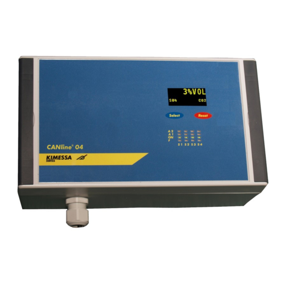
KIMESSA CANline 02 Operating Instructions Manual (63 pages)
Gas detector
Brand:
KIMESSA
| Category:
Security System
| Size: 2 MB
Table of Contents
Operating Instructions
1
Table of Contents
2
1 General Information
5
Imitation of Iability
5
Retention of Title
5
Warning
5
L Imitation of
5
Warranty
6
Conditions for Storage and Transport
6
Disposal of the Product
6
Importance of Instructions
6
Risk / Potential Hazard
7
Safety / Responsibility
7
If Ex-Measuring Sensors Are Connected in Hazardous Areas the Following Must be Observed
7
Definition of the Signal Words
9
Target Group, Electricians and Maintenance Technicians; Personal Protective Equipment
9
E Lectrical Installation
11
2 Usage
12
Introduction
12
3 Canline 02 Construction
13
4 Installation
14
Conditions of Use /Installation /Where and How will the Control Unit be Mounted
14
Wiring
14
Mechanical Installation of Can Line 02
15
Delivery Contents, Canline 02 Gas Detection Control Unit
16
Canline/Opening/Closing the Control Unit
16
Installation Measurements
16
Electrical Installation/Connecting the Control Unit
16
T2 Amp Fuses
17
Power Supply
17
Sensor-Cable BUS-Installation
17
Kimessa-Cable
18
Electrical Installation/Emc and ATEX
20
5 Canline 02 Connections
23
Wiring Schematic for 2 X 4
24
Wiring Schematic for 2 X Digital Bus Detectors
24
Wiring Schematic for Realy Contacst
25
6 User Comfort
26
Front View, Dimensions and Control Elements
26
Front Functions
26
Alarm Reset
27
Switch to Inactive" Button Function, One Sensor
27
Switch to Inactive " Button Function, Several Sensors
27
7 Switching on
28
8 Main Menu
29
Normal Operation / Sensor Display
30
First Steps to the Menu
30
System Info Menu
31
Next Service - System Info
31
Quantity of Sensors - System Info
32
Firmware Version
32
System Info
32
DC Voltage Info - System Power
33
Power DC Current - System Info
33
Alarm History 1 ... 10 - S Ensor 3 Alarm - History 2 - System Info
34
Relay Check 1 ... 5 / M Enu Structure / System Info
35
Exit to Main Menu
36
Exit to "Normal Operation
37
Normal Operation" Via "Exit" in the Main Menu
37
9 Commissioning
38
Commissioning Tools - BUS Cable, Connection Check
38
Connect Central with the PC - Startup Tools - Canline
38
10 Programming by Software
39
Start
40
Menu-Item „Firmware
40
Start: Import Data from Canline
42
Menu-Item „Settings
43
Menu-Item „Sensors
44
Menu-Item „Sensors" (Alarm-Matrix)
45
Menu-Item „Relays
46
Menu-Item „Timers
47
Menu-Item „File
48
Menu-Item „Print-Settings" (Protocol)
49
Menu-Item „Service
49
P Rint -S Ettings " (P Rotocol )
49
11 Button Programming
50
Sensor Settings - Menu Structure - System Info
50
Password Input - Sensor Settings - System Info
50
Sensor Number
51
Measuring Range
51
Sub-Menu - Sensors 1
51
Gas Designation, CO, CO2, Etc
52
The O2 Mode
52
Relay
53
Enu Structure
53
Auto-Reset, Manual
54
Reset Manual Override
54
Energizing / De-Energizing
54
Pulsating
54
Buzzer
54
Exit
54
Service Message - Menu
55
Reset - Service Now
56
Set Service Interval
56
Exit to Main Menu
56
12 Addressing the Bus Sensors
57
13 Bus-End Resistor
58
14 Maintenance / Repair
58
Maintenance / Service Display
60
Maintenance Cycle
60
15 Faults, Causes and Solutions
62
16 Declaration of Conformity
63
Advertisement
Kimessa CANline 02 User Manual (37 pages)
Alarm and Control System
Brand:
Kimessa
| Category:
Security System
| Size: 1 MB
Table of Contents
Table of Contents
2
1 General Information
4
Limitation of Liability
4
Retention of Title
4
Warning
4
Warranty
5
Conditions for Storage and Transport
5
Disposal of the Product
5
Importance of Instructions
5
Risk / Potential Hazard
6
Safety / Responsibility
6
If Ex-Measuring Sensors Are Connected in Hazardous Areas the Following Must be Observed
6
Definition of the Signal Words
8
Target Group, Electricians and Maintenance Technicians; Personal Protective Equipment
8
2 Usage
11
Introduction
11
3 Canline 02 Construction
12
4 Installation
13
Conditions of Use/Installation/Where and How will the Control Unit be Mounted
13
Mechanical Installation of Can Line 02
14
Delivery Contents, Canline 02 Gas Detection Control Unit
15
Canline/Opening/Closing the Control Unit
15
Installation Measurements
15
Electrical Installation/Connecting the Control Unit
16
T2 Amp Fuses
16
Power Supply
16
Sensor-Cable BUS-Installation
16
Kimessa-Cable
17
Electrical Installation/Emc and ATEX
18
5 Canline 02 Connections
21
Wiring Schematic for 2 X 4
22
Digital Bus Detectors
22
Wiring Schematic for Realy Contacst (Standard)
24
6 User Comfort
25
Front View, Dimensions and Control Elements
25
Front Functions
25
Alarm Reset
26
Switch to Inactive" Button Function, One Sensor
26
Switch to Inactive " Button Function, Several Sensors
26
7 Switching on
27
8 Main Menu
28
Normal Operation / Sensor Display
29
First Steps to the Menu
29
System Info Menu
30
Next Service - System Info
30
Quantity of Sensors - System Info
31
Firmware Version - System Info
31
DC Voltage Info - System Power
32
Power DC Current - System Info
32
Alarm History 1 ... 10 - S Ensor 3 Alarm - History 2 - System Info
33
Relay Check 1 ... 5 / M Enu Structure / System Info
34
Exit to Main Menu
35
Exit to "Normal Operation
36
Normal Operation" Via "Exit" in the Main Menu
36
9 Declaration of Conformity
37
Advertisement
Related Products
Kimessa CANline 04
Kimessa CANline 10
KIMESSA Categories
Security System
Control Systems
More KIMESSA Manuals
Login
Sign In
OR
Sign in with Facebook
Sign in with Google
Upload manual
Upload from disk
Upload from URL