
Related Manuals for Allied Healthcare AHP300


Summary of Contents for Allied Healthcare AHP300
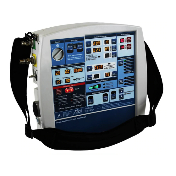
- Page 1 Model: AHP300 Electrically Controlled Ventilator 1720 Sublette Ave St. Louis, MO 63110 Phone 314-771-2400 S168-AHP300-001-CE Rev. - Covered by U.S.A. Patent #9,022,746 Other U.S.A. and Foreign Patents Pending...
-
Page 2: Table Of Contents
AHP300P Transport Ventilator Basic Model (requires pneumatic gas source) CAUTION: Federal law restricts this device to sale by or on the order of a physician. Warning: The AHP300 Ventilator should not be used on children with a weight of 5 kg (11 lbs) or less. -
Page 3: Intended Use
1. Intended Use: The AHP300 is intended to be used as an electrically controlled emergency ventilator that can use an external compressed gas source or its internal compressor. This ventilator is designed to provide emergency respiratory support by means of a face mask or tube inserted into the patient’s airway. -
Page 4: Product Description
-18C to 50C (0F to 122F) and 5% to 95% RH non-condensing. The AHP300 is intended to be used on one patient at a time. The unit can be reused after it has been cleaned and the single use patient circuit has been replaced. -
Page 5: Explanation Of Abbreviations
4. Explanation of Abbreviations: Delivered Tidal Volume Breaths per Minute (Respiratory Frequency) Respiratory Frequency Inspiratory Time Pounds per Square Inch cm H Centimeters of Water Kilopascal Milliliters Liters per minute Millimeters Light emitting diode Cardio Pulmonary Resuscitation Low pressure alarm High pressure alarm Relative Humidity Peak Inspiratory Pressure... -
Page 6: Controls And Connections
6. Controls and Connections: Control Panel Item # Description Item # Description Power On/Off Low Airway Pressure Alarm Setting Quick Start Adult Button Ventilation Mode Selection Quick Start Child Button Custom Mode Selection Tidal Volume Setting Parameter Adjustment Buttons O2 % Setting Control Lock Button I time Setting Manual Breath Button... - Page 7 Ventilator Connections: Item # Description Item # Description AC Power Remote Alarm Connection External Battery Patient Circuit Connection Port O2 Source (Fresh Gas) Patient Airway Pressure (blue) Air Source (Fresh Gas) Exhalation Valve Control Low Pressure O2 Source Air Intake Port (Fresh Gas)
-
Page 8: Operating The Ahp300 Ventilator
Oxygen and one for Medical Air. Connect the appropriate 3.4 bar (344 kPa) (50 psi) gas source with a minimum of 80 LPM flow capacity to these fittings. The AHP300 may be used without an external gas source. The AHP300 has an internal compressor that can be used to supply ambient air to the patient. - Page 9 Warning: Do not use unapproved patient circuits as loss of performance may result. Ventilator Patient Circuit The AHP300 uses a universal single limb ventilator patient circuit (pictured below). Allied Healthcare Products Adult Circuit Allied Healthcare Products Pediatric Circuit Part number L599-600 Part number L599-650 Dead space = 64.1 ml*...
- Page 10 *Too large of an apparatus dead space can affect the oxygen and other gas levels delivered to the patient. The addition of accessories may impact the dead space and must be considered when they are used. ^Addition of accessories may impact the exhalation resistance. Do not use circuits with “anti-static”...
- Page 11 Turn the ventilator “ON” by rotating the knob in the “Power” section of the control panel to the “│” position. Select the Desired Ventilation Mode: If the control lock is activated as shown below it must be deactivated before any adjustments can be made.
- Page 12 Select the Required Parameters: ‘ The ventilator will automatically populate the required fields with the current values. The table below shows the parameters that must be set in each mode. Volume Control Pressure Control CPAP Ti (Inspiratory Time) Required Required BPM (Frequency) Required...
- Page 13 If only oxygen is connected, the AHP300 will use the internal compressor to supply air and there will not be an alarm. If you select a %O2 of 70 when only oxygen is available, the ventilator will activate the internal compressor to provide the required air flow so that the set tidal volumes can be delivered.
- Page 14 Spontaneous Breathing by the Patient: Should the patient begin to breathe spontaneously the AHP300 will sense this breath and deliver the breath per the ventilator setting. The LED (light) indicating a spontaneous breath by the patient will come on after the spontaneous breath is delivered by the ventilator.
-
Page 15: Ventilation Modes
For safety, the ventilator contains an internal anti-suffocation valve. Warning: A CBRN Filter is required when the ventilator compressor is used in an environment where air is not safe to breath. 8. Ventilation Modes: Volume Control: In volume control the ventilator will deliver a set tidal volume at a time cycled interval determined by the inspiratory time and respiratory frequency (BPM) settings. - Page 16 Pressure Control: In this mode the ventilator will deliver flow to the patient until a set pressure is reached. The flow rate will be variable and will slow down as the airway pressure approaches the set pressure. The ventilator will measure the time and pressures at various points in the breath and then adjust the flows automatically to achieve the pressure curve shown below.
- Page 17 Seamless Transition between Volume and Pressure Modes To facilitate rapid and safe adjustment of therapy by respiratory care professionals the AHP300 incorporates what we call “Seamless Mode Transition”. When moving from a pressure regulated mode to a volume regulated mode, the prior...
-
Page 18: Breath Types
9. Breath Types: Assist Control (AC): The ventilator will guarantee that the numbers of breaths given will be equal to or greater than the BPM setting. The patient may trigger additional breaths. When the ventilator detects a spontaneous breath it will deliver a breath per the volume or pressure control settings. -
Page 19: Programmable Presets
10. Programmable Presets: The ventilator has 2 different programmable presets, Quick Start and Custom modes. The Quick Start modes are for adult and child and have a button for each mode. There are 3 Custom modes that can be set up. One must use the Custom Mode button and the parameter adjustment buttons to select the desired Custom Mode. - Page 20 Table 1 Adult Button Child Button Ventilation Mode: Pressure AC Ventilation Mode: Pressure AC BPM Setting: BPM Setting: Setting: 2 seconds Setting: 1.0 seconds % O2 100% % O2: 100% PIP: 15 cmH2O PIP: 15 cmH2O PEEP: 3 cm H2O PEEP: 3 cm H2O Low Pressure Alarm:...
- Page 21 Using the Quick Start Buttons: To use the Quick Start mode push one of the Quick Start buttons and the light below the button will blink and the stored settings will be displayed. Push the button a second time and these settings will be activated. If you do not push the button a second time in 10 seconds the displays will revert back to the current ventilator settings and you will need to start the process over.
-
Page 22: Custom Modes
These custom modes allow a common treatment options to be preprogrammed on all AHP300 ventilators that a hospital or EMS service may use based on the physician’s direction. For example custom mode #1 could be CPAP at 10 cmH2O. - Page 23 Table 2 Default Custom Modes Ventilation Mode: Volume Control Breath Type: Assist Control BPM Setting: Setting: 1 seconds % O2: 100% Tidal Volume: 500 ml PEEP: 0 cm H2O Low Pressure Alarm: 10 cm H2O High Pressure Alarm: 30 cm H2O Trigger Sensitivity: 2 cm H2O The ventilator will begin operating in the stored default settings.
- Page 24 now flash rapidly. You may now adjust the mode and any applicable parameter. To store these settings in the current custom mode, the user will depress and hold the “Custom Mode Selection” button first and then press the “Mode Selection” button. The ventilator will sound a short beep to indicate the custom mode has been saved.
-
Page 25: O2 Conserve Mode
11. O2 Conserve Mode: O2 Conserve Mode: This mode allows the use up to 10 LPM of oxygen at .2 to 2.8Bar (20.7 to 275kPa), (3 to 40 psi) through the DISS port or .2 to 2.8Bar (20.7 to 68.9kPa) (3 to 10 psi) through the low pressure, low flow O connection. -
Page 26: Manual Breaths
12. Manual Breaths: Manual breaths may be delivered using the manual breath button. Each time this button is pushed the ventilator will deliver one breath with the set tidal volume. The unit will deliver only one breath per the ventilator settings when the button is pushed. The button must be released and pushed again to deliver a second breath. -
Page 27: Alarms
14. Alarms: Electronic Alarms: Alarm Sound Level is greater than 70 decibels. A large general alarm indicator light will light when any alarm is detected. The light next to the specific alarm will also turn on. Alarms will clear the audible alarm when the alarm condition is cleared but not the visual indicators next to the specific alarm. - Page 28 Clears 8 seconds after pressure is restored. The alarm is an indication that the unit may stop operating soon and the gas source should be replaced immediately. The AHP300 will automatically switch to 100% air when the ventilator can no longer operate on the compressed O source.
- Page 29 The plateau pressure may be measured by temporarily occluding the outlet of the patient valve during and for a short period at the end of inspiration. The PIP display will show the peak inspiratory pressure for a short time at the end of inspiration and then show the current pressure which in this case will be the plateau pressure.
-
Page 30: External Alarm Connection
15. External Alarm Connection: An external alarm connection is provided. This connection uses a standard ¼ inch phono jack. This jack is commonly used as an auxiliary connection in nurse call systems. The connection is normally open and closes when an alarm occurs. The connection will be capable of handling a maximum of .5 amps @ 125 volts AC or 1 amp at 30 volts DC signal. -
Page 31: Battery Parameters
16. Battery Parameters: Battery Level The battery level is shown in the Battery Parameters of the control panel. The ventilator will monitor battery voltage and display the current battery voltage. When the battery level has reached a low level the left 2 lights will turn red indicating the ventilator should be connected to an external power source. -
Page 32: Ac Power Inlet And Auxiliary Power Connection
The MCV-AUXBAT contains batteries capable of delivering 10 amp-hours of power. This is approximately twice as much power as contained in the internal battery of the AHP300. Use of this device can approximately triple the battery run time. - Page 33 AHP300 with Auxiliary Power Source MCV-AUXBAT Warning: Auxiliary power connection is keyed. Make sure that connectors are properly aligned before insertion, do not force. Damage to the ventilator may occur making the ventilator unavailable for use. Caution: Use only the MCV-AUXBAT external battery pack, damage to the ventilator may occur with a non-approved battery pack.
-
Page 34: Cleaning
18. Cleaning: The AHP300 should be cleaned after each use. To clean the ventilator, keep the gas supply hose on the unit to prevent contamination of the oxygen circuit. Warning: Cleaning procedures should be performed in an environment free of oil and petroleum based products. -
Page 35: Check Out Procedure
Confirm that the low gas LED indicator is on and the main alarm light is on. b. Confirm that the low source gas alarm sounds Should the unit fail any of the tests contact Allied Healthcare Products, Inc. Service Department at 314-771-2400. -
Page 36: Pneumatic Diagram
20. Pneumatic Diagram:... -
Page 37: Maintenance
Particle Filter Replacement: Air Intake Port The AHP300 contains a particle filter located inside the air inlet on the side of the unit. This filter cleans the ambient air drawn in by the compressor. This filter should be checked every 4 months and changed if visibly dirty. Stockpiled ventilators that are not being used may skip this step as no dirt will collect when not in use. - Page 38 Battery Maintenance/ Replacement: The AHP300 battery level should be checked every four months. If not kept on continuous charge, charge the battery at this time. If the battery does not reach full charge within 5 hours, the battery should be replaced at that time. If the battery does not recharge in 7 hours all the lights will blink on the battery indicator letting the user know the battery does not have full capacity and should be replaced.
- Page 39 This maintenance also includes calibration and performance testing of the ventilator. This maintenance must be performed by Allied Healthcare Products or personnel trained by Allied Healthcare Products on how to maintain this ventilator. If problems are noted with this product, contact the Allied Healthcare Products, Inc.
- Page 40 Calibration and Battery Replacement Replace Battery Calibrate & Performance Test Unit * Must be performed by Allied Healthcare Products or by factory trained personnel. Year 4 Maintenance Check List Verification of Calibration and Function Time Required 30 Minutes...
- Page 41 Connect the ventilator circuit to the AHP300 outlet and the ventilator calibrator. Set the tidal volume to 300 setting and turn the AHP300 on. Readjust the gas source to 50 psi if necessary. Set the gas selection to 100% O2.
- Page 42 The following is a sample log that may be used for recording test records during Yearly Verification of Calibration and Function. Test Log Test Date: Acceptable Range Reading 9 to 11 18 to 22 27 to 33 36 to 44 45 to 55 54 to 66 Tidal Volume...
- Page 43 AC Inlet Fuse Replacement The AC power inlet is protected by 2 fuses. If a fuse is blown the unit will not charge the battery. Should one of the fuses need to be replaced it can be replaced as follows; Remove the fuse by tuning the fuse holder ¼...
-
Page 44: Specifications
Specifications: Power/Gas Supply A. Gas Supply Pressure: High Pressure: 280 kPa (40.6 psi) to 600 kPa (87.0 psi) Oxygen DISS and Air DISS or 69 kPa (10 psi) to 275 kPa (40.0 psi) Oxygen DISS in O2 conservation mode. Connections: CGA V5 O2 and Air DISS Inputs ISO 5356 22 mm Output Low Pressure O2: Up to 10 LPM at less than 10 PSI Connections: 1/8”... - Page 45 I. Tidal Volume (V Accuracy: ±10% with 100% Oxygen or 100% Air, ±12% for blended gases For temperatures below 15F: Accuracy: ±12% with 100% Oxygen or 100% Air, ±14% for blended gases Flows from 5 to 60 LPM produce the following tidal volumes Tidal Volume Range .5 Second Inspiratory Time = 40ml to 500ml Tidal Volume Range .75 Second Inspiratory Time = 60ml to 750ml Tidal Volume Range 1 Second Inspiratory Time = 80ml to 1000ml...
- Page 46 S. Custom Ventilation Modes: The ventilator allows 3 custom modes to be stored and recalled. The custom modes may be any of the ventilation modes and the appropriate parameters. T. Battery Parameters: A battery level indicator shows the battery status for the battery in use.
- Page 47 External Alarm Connection: A ¼ Phono style jack connection will be provided. This connection will provide a normally open switch that will close when an alarm occurs. The connection will be capable of handling a maximum of .5 amps @ 125 volts AC or 1 amp at 30 volts DC signal. The minimum signal is 1 ma @ 5 volts.
-
Page 48: Accessories And Replacement Parts
22. Accessories and Replacement Parts: Part Number Description Qty per Usage See page for Package instructions 6’ Adult Single Limb Vent Circuit L599-600 Disposable (22mm Corrugated Tubing) Single Patient use 6’ Pediatric Single Limb Vent Circuit L599-650 Disposable (15mm Corrugated Tubing) Single Patient use L595161-10 Disposable Cuffed Oxygen Mask,... -
Page 49: Nbr Filter
This filter should be used when a patient may breath spontaneously in a hazardous environment. The air inlet fitting on the AHP300 has an internal 40 mm threaded connection per EN 148- 1:1999. This is the standard thread connection for respiratory protective devices typically used by industry, law enforcement, and the military. -
Page 50: Oxygen Cylinder Depletion Times
24. Oxygen Cylinder Depletion Times: These times are approximate and assume full cylinder capacity. Always monitor the cylinder pressure and low pressure alarm to make sure you do not run out of oxygen. E Cylinder Capacity = 682 Liters Oxygen Capacity (4.6 Liters Water Capacity) Breaths per Minute Tidal... -
Page 51: Approximate Tidal Volume Settings Based On Height
25. Approximate Tidal Volume Settings based on Height: APPROXIMATE SETTINGS BASED ON PATIENT HEIGHT Tidal Volume (ml) 900 1000 1100 1200 @10 ml/Kg Height Male 22.5* 35* 60 inches (cm) (57) (89) (114) (134) (147) (152) (163) (175) (185) (196) (208) (218) (229) Height Female 22.5* 35* inches (cm) -
Page 52: Warranty
26. Warranty:... -
Page 53: Applicable Standards
Increase the separation between the equipment Consult the manufacturer or field service technician for help The AHP300 is intended to provide emergency respiratory support for children and adults. The product is intended to meet the following safety and performance standards: Performance and Safety Requirements ... - Page 54 For the latest revision of the instruction manual, please refer to the company website at www.alliedhpi.com. This manual is also available in other languages. Please call 800-411-5136 for more information on obtaining this manual in other languages. Authorized Representative in Europe Emergo Europe Molenstraat 15 2513 BH, The Hague...
Need help?
Do you have a question about the AHP300 and is the answer not in the manual?
Questions and answers