
Subscribe to Our Youtube Channel
Related Manuals for Grundfos alpha2l


Summary of Contents for Grundfos alpha2l
- Page 1 GRUNDFOS INSTRUCTIONS GRUNDFOS ALPHA2 L Installation and operating instructions ALPHA2 L ALPHA2 L ALPHA2 LPHA2 LPHA2 www.grundfos.com...
- Page 2 EC declaration of conformity We, Grundfos, declare under our sole responsibility that the product GRUNDFOS ALPHA2 L, to which this declaration relates, is in conformity with these Council directives on the approximation of the laws of the EC member states: —...
-
Page 3: Table Of Contents
CONTENTS Page Symbols used in this document ........General description . -
Page 4: Symbols Used In This Document
Warning Prior to installation, read these installation and operating instructions. Installation and operation must comply with local regulations and accepted codes of good practice. Warning The use of this product requires experience with and knowledge of the product. Persons with reduced physical, sensory or mental capabilities must not use this product, unless they are under supervision or have been instructed in the use of the product by a person responsible for their safety. -
Page 5: General Description
2.1 The GRUNDFOS ALPHA2 L circulator pump 2.2 Advantages of installing a GRUNDFOS ALPHA2 2.1 The GRUNDFOS ALPHA2 L circulator pump The GRUNDFOS ALPHA2 L circulator pump is designed for the circulation of water in heating systems. Install the GRUNDFOS ALPHA2 L in •... -
Page 6: Applications
75 °C 90 °C 110 °C Fig. 2 Pumped liquids and operating conditions GRUNDFOS ALPHA2 L is suitable for • systems with constant or variable flows where it is desirable to optimise the setting of the pump duty point •... - Page 7 3.3 System pressure Maximum 1.0 MPa (10 bar). See fig. 2. 3.4 Relative air humidity (RH) Maximum 95 %. See fig. 2. 3.5 Enclosure class IP42. See fig. 2. 3.6 Inlet pressure Minimum inlet pressure in relation to liquid temperature. See fig. 2. Minimum inlet pressure Liquid temperature [MPa]...
-
Page 8: Installation
Mounting the GRUNDFOS ALPHA2 L Arrows on the pump housing indicate the liquid flow direction through the pump. 12.2 Installation dimensions, GRUNDFOS ALPHA2 L XX-40, XX-45, XX-50, XX-60. 1. Fit the two gaskets supplied when the pump is mounted in the pipe. -
Page 9: Pumped Liquids
4.2 Control box positions ALPHA2 L PHA2 PHA2 Fig. 4 Control box positions Warning The pumped liquid may be scalding hot and under high pressure! Drain the system or close the isolating valves on either side of the pump before the screws are removed. When the position of the control box has been changed, fill the Caution system with the liquid to be pumped or open the isolating valves. - Page 10 The heat loss from the pump and pipework can be reduced by insulating the pump housing and the pipe. See fig. 5. As an alternative, polystyrene insulation shells can be ordered from Grundfos. See Accessories. Do not insulate the control box or cover the control panel.
-
Page 11: Electrical Connection
5. Electrical connection ALPHA2 L ALPHA2 L + 6% 1 x 230V ~ , 50 Hz -10% PHA2 2 PHA2 PHA2 A A L PHA2 2 PHA2 PHA2 Min. ø5 mm Max. ø10 mm Max. 1.5 mm 7 mm 7 mm 12 mm 17 mm Click... -
Page 12: Control Panel
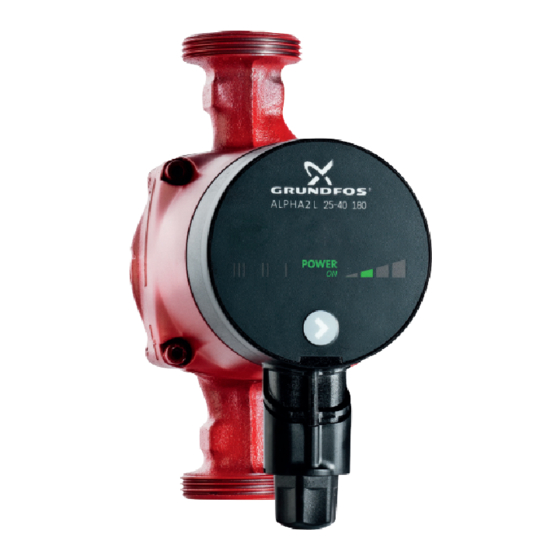
6.1 Elements on the control panel ALPHA2 L 25-40 180 POWER Fig. 7 GRUNDFOS ALPHA2 L control panel The control panel on the GRUNDFOS ALPHA2 L comprises: Pos. Description "POWER ON" indicator light Seven light fields indicating the pump setting Push-button for selection of pump setting 6.2 "POWER ON"... - Page 13 6.3 Light fields indicating the pump setting GRUNDFOS ALPHA2 L has seven optional settings which can be selected with the push-button. See fig. 7, pos. 3. The pump setting is indicated by seven different light fields. See fig. 8. POWER III II I Fig.
-
Page 14: Setting The Pump
7. Setting the pump Contents: 7.1 Pump setting for system type 7.2 Pump control. 7.1 Pump setting for system type ALPHA2 L PHA2 PHA2 POWER POWER POWER ER POWER POWER POWER OWER POWER POWER POWER POWER POWER POWER Fig. 9 Selection of pump setting for system type Factory setting = Highest proportional-pressure curve (PP2). - Page 15 7.2 Pump control During operation, the pump head will be controlled according to the principle "proportional-pressure control" (PP) or "constant-pressure control" (CP). In these control modes, the pump performance and consequently the power consumption are adjusted according to the heat demand in the system.
-
Page 16: Systems With Bypass Valve Between Flow And Return Pipes
8. Systems with bypass valve between flow and return pipes Contents: 8.1 Purpose of bypass valve 8.2 Manually operated bypass valve 8.3 Automatic bypass valve (thermostatically controlled). 8.1 Purpose of bypass valve ALPHA2 L PHA2 PHA2 2 2 2 BYPASS ALPHA2 min. - Page 17 8.3 Automatic bypass valve (thermostatically controlled) Follow this procedure: 1. Adjust the bypass valve with the pump in setting I (speed I). The minimum flow (Q ) for the system must always be observed. min. Consult the manufacturer's instructions. 2. When the bypass valve has been adjusted, set the pump to the lowest or highest constant-pressure curve.
-
Page 18: Start-Up
9. Start-up Contents: 9.1 Before start-up 9.2 Venting the pump 9.3 Venting of heating systems. 9.1 Before start-up Do not start the pump until the system has been filled with liquid and vented. The required minimum inlet pressure must be available at the pump inlet. - Page 19 The heating system can be vented via an air escape valve installed above the pump (1). In heating systems that often contain much air, Grundfos recommends the installation of pumps with pump housing with air separator, i.e. ALPHA2 L pumps, type ALPHA2 L XX-XX A.
-
Page 20: Pump Settings And Pump Performance
10. Pump settings and pump performance Contents: 10.1 Relation between pump setting and pump performance. 10.1 Relation between pump setting and pump performance Figure shows the relation between pump setting and pump performance by means of curves. See also 13. Performance curves. - Page 21 Setting Pump curve Function ALPHA2 L runs at a constant speed and consequently on a constant curve. Speed II In speed II, the pump is set to run on the medium curve under all operating conditions. See fig. 13. ALPHA2 L runs at a constant speed and consequently on a constant curve.
-
Page 22: Fault Finding Chart
11. Fault finding chart Warning Before starting any work on the pump, make sure that the electricity supply has been switched off and that it cannot be accidentally switched on. Control Fault Cause Remedy panel 1. The pump Light off. a) One fuse in the Replace the fuse. -
Page 23: Technical Data And Installation Dimensions
12. Technical data and installation dimensions Contents: 12.1 Technical data 12.2 Installation dimensions, GRUNDFOS ALPHA2 L XX-40, XX-45, XX- XX-60. 12.3 Installation dimensions, GRUNDFOS ALPHA2 L XX-40, XX-45, XX- 12.4 Installation dimensions, GRUNDFOS ALPHA2 L XX-40, XX-45, XX- 12.1 Technical data... - Page 24 12.2 Installation dimensions, GRUNDFOS ALPHA2 L XX-40, XX-45, XX-50, XX-60 Fig. 14 Dimensional sketches, ALPHA2 L XX-40, XX-45, XX-50, XX-60 Dimensions Pump type ALPHA2 L 15-40 130 ALPHA2 L 20-40 130 1 1/4 ALPHA2 L 25-40 130 1 1/2 ALPHA2 L 25-40 180...
- Page 25 12.3 Installation dimensions, GRUNDFOS ALPHA2 L XX-40, XX-45, XX-60 For the German market Fig. 15 Dimensional sketches, ALPHA2 L XX-40, XX-45, XX-60 Dimensions Pump type ALPHA2 L 15-40 130 DE ALPHA2 L 20-40 130 DE 1 1/4 ALPHA2 L 25-40 130 DE...
- Page 26 12.4 Installation dimensions, GRUNDFOS ALPHA2 L XX-40, XX-45, XX-60 For the Austrian and Swiss markets Fig. 16 Dimensional sketches, ALPHA2 L XX-40, XX-45, XX-60 Dimensions Pump type ALPHA2 L 15-40 130 AT/CH ALPHA2 L 20-40 130 AT/CH 1 1/4 ALPHA2 L 25-40 130 AT/CH...
-
Page 27: Performance Curves
13. Performance curves Contents: 13.1 Guide to performance curves 13.2 Curve conditions 13.3 Performance curves, ALPHA2 L XX-40 13.4 Performance curves, ALPHA2 L 20-45 N 150 13.5 Performance curves, ALPHA2 L XX-50 13.6 Performance curves, ALPHA2 L XX-60. - Page 28 13.1 Guide to performance curves Each pump setting has its own performance curve (Q/H curve). A power curve (P1 curve) belongs to each Q/H curve. The power curve shows the pump power consumption (P1) in Watt at a given Q/H curve. The P1 value corresponds to the value that can be read from the pump display.
- Page 29 13.2 Curve conditions The guidelines below apply to the curves on the next pages: • Test liquid: Airless water. The curves apply to a density of ρ = 983.2 kg/m • and a liquid temperature of +60 °C. • All curves show average values and should not be used as guarantee curves.
-
Page 30: Q [M³/H]
13.3 Performance curves, ALPHA2 L XX-40 [kPa] [kP a] Q [m³/h] Q [m³/h] Q [l/s] Q [l/s] [W ] Q [m³/h] Q [m³/h] Fig. 18 Performance curves, ALPHA2 L XX-40 13.4 Performance curves, ALPHA2 L 20-45 N 150 [kPa] Q [m³/h] Q [l/s] Q [m³/h] Fig. - Page 31 13.5 Performance curves, ALPHA2 L XX-50 [kPa] Q [m³/h] Q [l/s] Q [m³/h] Fig. 20 Performance curves, ALPHA2 L XX-50 13.6 Performance curves, ALPHA2 L XX-60 [kPa] Q [m³/h] Q [l/s] Q [m³/h] Fig. 21 Performance curves, ALPHA2 L XX-60...
-
Page 32: Features
14. Features Contents: 14.1 Nameplate 14.2 Type key. 14.1 Nameplate ALPHA2L 25-40 180 ALPHA2 25-40 180 ALPHA2 L 25-40 180 POWER AUTO ADAPT P1(W) Prod. No. 95047562 Serial No. 00000001 Min. 0.05 KM07183 PC 0833 TF110 Max. 0.19 IP 42 230V ~ 50Hz 0.23 - Part 2... -
Page 33: Accessories
25 - XX 32 - XX 505822 15 - XX A 25 - XX A 595562 Fig. 23 Accessories Accessories for GRUNDFOS ALPHA2 L. See fig. 23. Accessories include • fittings (unions and valves) • insulation kits (insulation shells) •... -
Page 34: Disposal
This product or parts of it must be disposed of in an environmentally sound way: 1. Use the public or private waste collection service. 2. If this is not possible, contact the nearest Grundfos company or service workshop. Subject to alterations. - Page 35 GRUNDFOS Hellas A.E.B.E. Минске Turkey 20th km. Athinon-Markopoulou Av. New Zealand 220125, Минск GRUNDFOS POMPA San. ve Tic. Ltd. Sti. P.O. Box 71 ул. Шафарнянская, 11, оф. 56 GRUNDFOS Pumps NZ Ltd. Gebze Organize Sanayi Bölgesi GR-19002 Peania Тел.: +7 (375 17) 286 39 72, 286 39 73...
- Page 36 Being responsible is our foundation Thinking ahead makes it possible Innovation is the essence 95047490 1212 Repl. 95047490 0908 www.grundfos.com...
Need help?
Do you have a question about the alpha2l and is the answer not in the manual?
Questions and answers