Sign In
Upload
Manuals
Brands
simex Manuals
Controller
multicon cmc-99
simex multicon cmc-99 Manuals
Manuals and User Guides for simex multicon cmc-99. We have
1
simex multicon cmc-99 manual available for free PDF download: User Manual
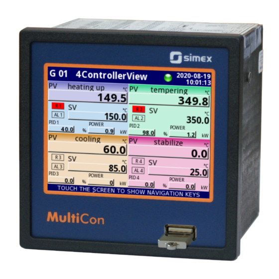
simex multicon cmc-99 User Manual (300 pages)
compact-multichannel-controller with a capability to record data
Brand:
simex
| Category:
Controller
| Size: 5 MB
Table of Contents
Table of Contents
2
1 Basic Requirements and User Safety
5
The Use of Touch-Screen
6
2 General Characteristics
6
3 Technical Data
9
4 Device Installation
10
Unpacking
11
Assembly
12
Connection Method
14
Available Modules
17
Maintenance
31
5 Introduction to Multicon CMC-99/141
31
Understanding Controller/Data Recorder Multicon CMC-99/141
31
Logical Channels
32
Groups
34
Hardware Configurations
35
6 Working with the Multicon CMC-99/141
36
Multicon CMC-99/141 Power up
36
The Use of the Touch-Screen
36
Display
36
Information Bar
37
Navigation Bar
38
Data Panels
39
Important Messages
42
7 Configuration of the Multicon CMC-99/141
43
Edit Dialogues
43
Main Menu Selection Panel
46
Files Management
47
Device Information, Licence, Firmware Update, Remote Display, Export Manual and Renew Configuration
53
Device Configuration
56
Configuration Menu Structure
59
Settings
61
General Settings
63
Logical Channels
67
Logical Channels - General Settings
67
Logical Channels - Hardware Input Mode
84
Logical Channels - Hardware Output Monitor Mode
87
7.8.1. Logical Channels - General
87
Logical Channels - Modbus Mode
89
7.8.1. Logical Channels - General
90
Logical Channels - Set Point Value Mode
92
User Manual for - CONTROLLER/DATA RECORDER Multicon CMC
93
Logical Channels - Math Function Mode
95
7.8.1. Logical Channels - General
95
7.8.1. Logical Channels - General
96
Logical Channels - Controller Mode
105
7.8.1. Logical Channels - General
106
Logical Channels - Profile/Timer Mode
107
7.8.1. Logical Channels - General
107
7.8.1. Logical Channels - General
108
Logical Channels - Profile/Timer (Cycle Counter) Mode
109
7.8.1. Logical Channels - General
109
Logical Channels - Data from Other Channel Mode
110
7.8.1. Logical Channels - General
110
Examples of Logical Channels Configuration
111
Application of Logical Channel in the Hardware Input Mode for UI4 Module
111
7.8.1. Logical Channels - General
111
Application of Logical Channel in the Hardware Input Mode for TC4 Modules
118
Application of Logical Channel in the Hardware Input Mode for RT4 Modules
121
Application of Logical Channel in the Hardware Output Monitor Mode for R45
123
Modules
123
Application of Logical Channel in the Modbus Mode
125
Application of Logical Channel in the Hardware Input for TC8 Modules
127
Application in Math Function Mode
129
Application of Logical Channel in the Controller Mode
131
Application of Logical Channel in the Profile/Timer Mode
133
Application of Logical Channel in the Hardware Input Mode and Data from
135
Other Channel for FT4 Module
135
User Manual for - CONTROLLER/DATA RECORDER Multicon CMC
135
Built-In Inputs
137
Built-In Inputs - General Settings
137
Built-In Inputs - Input Modules
139
Built-In Inputs - Binary Input Inp.x2 : Digital 24V
139
Built-In Inputs - Demo Input Numbered X3, X4, X5
140
Built-In Inputs - Modules
141
Voltage and Current Measurement Modules
141
Mixed UIN/UID Modules
141
Isolated Current Inputs Module
143
Analogue Flowmeter Modules
143
Pulse Flowmeter Modules
144
Thermocouples Sensor Measurement Modules
145
Settings
146
RTD Measurement Modules
147
Isolated Universal Inputs Modules
147
Optoisolated Digital Inputs Modules
148
Optoisolated Universal Counters Modules
148
Optoizolated Hourmeters Modules
150
Built-In Outputs
152
Built-In Outputs - General Settings
152
Configurations
153
Built-In Output - Relays, Sound Signal, Virtual Relays
154
Settings
156
Settings
157
Build-In Output - PWM (Pulse-Width Modulation) Mode for SSR Relay Output
158
Built-In Output - Current Output
160
Examples of Build-In Output Configurations
162
Application of the Output for R45 Modules
162
Output
163
Application of Output for IO Modules
164
External Outputs
165
External Outputs - General Settings
165
External Outputs - Control Type: as a Relay
167
External Outputs - Control Type: as a Linear Output
169
Examples of External Output Configurations
171
Application of External Output for Protocol Modbus in the MASTER Mode
171
Profiles/Timers
174
Profile/Timer - General Settings
174
Profiles/Timers - Triggering Mode: Level (Gate), Edge (Once), Edge (Retrig.)
178
Time
178
Profiles/Timers - Triggering Mode: on Time
180
Examples of Profile/Timer Configurations
182
Application of the Profiles/Timers
182
Application of the Profiles/Timers Triggered on Time
184
Controllers
186
Controllers - General Settings
186
Examples of Controller Configurations
189
Application of the Controllers
189
Application of the Controllers in Cooperation with Heater Which Is Controlled by SSR Output
190
Groups
193
Groups - General Settings
193
Settings
197
Groups - Logging Options
198
Groups - Examples of Visualisations of Groups
200
Single Channel - One Big Needle
200
Three Channels View - One Bigger, Two Smaller
201
Modbus
202
Modbus - General Settings
203
Modbus - SLAVE Mode
203
Modbus SLAVE - Modbus Templates for SLAVE Mode
204
Modbus SLAVE - Device Channels for SLAVE Mode
205
Modbus SLAVE - the Modbus Protocol Handling
207
Modbus SLAVE - List of Registers
207
Block
207
Modbus SLAVE - Transmission Errors Handling
209
Modbus SLAVE- Example of Query/Answer Frames
209
Modbus - MASTER Mode
210
Modbus MASTER - Device Templates Parameter Block
211
Modbus MASTER - Device Channels Parameter Block
212
Modbus MASTER - Register Settings
214
Modbus MASTER - Register Blocks Parameter Block
215
Modbus - Example of Modbus Protocol Configuration in the Device
217
Input Configuration of Modbus Protocol in MASTER Mode
217
Settings
217
Configuration of the Modbus Input in the MASTER Mode
220
Module
220
Network and Remote Display Settings
223
Access Options
225
Printouts
229
Notifications
231
8 Appendices
234
Ps3, Ps4, Ps32, Ps42 - Power Supply Module
234
Ui4, Ui8, Ui12, U16, U24, I16, I24 - Voltage and Current Measurement Modules
235
Ui4N8, Ui4D8, Ui8N8, Ui8D8 - Mixed Uin/Uid Modules
241
Is6 - Isolated Current Inputs Module
244
Fi2. Fi4, Ft2, Ft4 - Flowmeter Modules
246
Tc4, Tc8, Tc12 - Thermocouple Sensor Measurement Modules
249
Rt4 , Rt6 - Rtd Measurement Modules
252
Un3, Un5 - Optoisolated Universal Inputs Modules
255
Module
255
D8, D16, D24 - Optoisolated Digital Inputs Module
261
Cp2, Cp4 - Optoisolated Universal Counters Modules
263
Hm2, Hm4 - Optoizolated Hourmeters Modules
266
S8, S16, S24 - Solid State Relay Drivers Modules
268
Output
268
R45, R81, R65, R121 - Relay Modules
272
Io2, Io4, Io6, Io8 - Passive Current Output
274
Communication Modules
278
Multipint Mlp-149 - External Printer
279
General Characteristic
279
Technical Data
279
Working with Multiprint MLP-149
280
Data Format
285
Settings
290
Direct Access to Log Files Using Http Protocol
294
Advertisement
Advertisement
Related Products
simex multicon cmc-141
Simex MultiCon CMC-N16
Simex MultiCon CMC-99/141
Simex cuff M
Simex cuff S
Simex CRV-808
Simex CRV-809
Simex PUR-44D
Simex PUR-49D
Simex PUR-94
simex Categories
Measuring Instruments
Cash Counter
Controller
Data Loggers
Control Unit
More simex Manuals
Login
Sign In
OR
Sign in with Facebook
Sign in with Google
Upload manual
Upload from disk
Upload from URL