Table of Contents
Advertisement
Installation Instructions
24V dc FLEX I/O
16 Sink Input Module
(Cat. No. 1794-IB16)
3
4
Module Installation
This module mounts on a 1794 terminal base unit.
1. Rotate keyswitch (1) on terminal base unit (2) clockwise to position 2
as required for this type of module.
2. Make certain the flexbus connector (3) is pushed all the way to the left
to connect with the neighboring terminal base/adapter. You cannot
install the module unless the connector is fully extended.
3. Make sure that the pins on the bottom of the module are straight so
they will align properly with the connector in the terminal base unit.
If you remove or insert the module while the
WARNING
backplane power is on, an electrical arc can occur.
This could cause an explosion in hazardous location
!
installations. Be sure that power is removed or the
area is nonhazardous before proceeding.
4. Position the module (4) with its alignment bar (5) aligned with the
groove (6) on the terminal base.
5. Press firmly and evenly to seat the module in the terminal base unit.
The module is seated when the latching mechanism (7) is locked into
the module.
FLEX I/O is a trademark of
Publication 1794 IN072C-EN-P - October 2001
Rockwell Automation
7
1
2
6
5
Advertisement
Table of Contents

Related Manuals for AB Quality 1794-IB16

Summary of Contents for AB Quality 1794-IB16
- Page 1 Installation Instructions 24V dc FLEX I/O 16 Sink Input Module (Cat. No. 1794-IB16) Module Installation This module mounts on a 1794 terminal base unit. 1. Rotate keyswitch (1) on terminal base unit (2) clockwise to position 2 as required for this type of module.
- Page 2 24V dc FLEX I/O 16 Sink Input Module To use this module in a complementary I/O system, ATTENTION refer to your Remote I/O Adapter module documentation. Important User Information Because of the variety of uses for the products described in this publication, those responsible for the application and use of these products must satisfy themselves that all necessary steps have been taken to assure that each application and use meets all performance and safety requirements, including any applicable laws,...
- Page 3 24V dc FLEX I/O 16 Sink Input Module 3 Identifies information about practices or ATTENTION circumstances that can lead to personal injury or death, property damage, or economic loss. Environment and Enclosure ATTENTION This equipment is intended for use in a Pollution Degree 2 industrial environment, in overvoltage Category II applications (as defined in IEC publication 60664–1), at altitudes up to 2000 meters without derating.
- Page 4 24V dc FLEX I/O 16 Sink Input Module Preventing Electrostatic Discharge ATTENTION This equipment is sensitive to electrostatic discharge, which can cause internal damage and affect normal operation. Follow these guidelines when you handle this equipment: Touch a grounded object to discharge potential static.
- Page 5 24V dc FLEX I/O 16 Sink Input Module 5 Wiring to a 1794 TB3 or TB3S Terminal Base Unit If you connect or disconnect wiring while the field WARNING side power is on, an electrical arc can occur. This could cause an explosion in hazardous location installations.
- Page 6 24V dc FLEX I/O 16 Sink Input Module Row A 9 10 11 12 13 14 15 Row B 19 20 21 22 23 24 25 26 27 28 29 30 31 32 Row C 35 36 37 38 39 40 41 42 43 44 45 46 47 48 49 50 Label placed at top of wiring area.
- Page 7 24V dc FLEX I/O 16 Sink Input Module 7 Input Voltage Common Input Terminal Terminal Terminal Input 0 C-35 B-17 Input 1 C-36 B-18 Input 2 C-37 B-19 Input 3 C-38 B-20 Input 4 C-39 B-21 Input 5 C-40 B-22 Input 6 C-41 B-23...
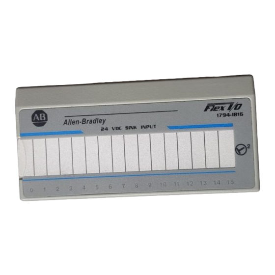
- Page 8 24V dc FLEX I/O 16 Sink Input Module Indicators Allen Bradley 1794-IB16 24 VDC SINK INPUT A = Status indicators – yellow – show status of individual inputs. B = Insertable label for writing individual input designations. Memory Map Dec.
- Page 9 24V dc FLEX I/O 16 Sink Input Module 9 Setting the Input Filter Time You can select the input filter time (FT) for each group of channels (channels 00 through 11, or channels 12 through 15). Select the input filter time by setting the corresponding bits in the output image table (complementary word) for the module.
- Page 10 24V dc FLEX I/O 16 Sink Input Module The following information applies when operating this equipment in hazardous locations: Products marked CL I, DIV 2, GP A, B, C, D" are suitable for use in Class I Division 2 Groups A, B, C, and D Hazardous Locations and nonhazardous locations only.
- Page 11 24V dc FLEX I/O 16 Sink Input Module 11 Specifications - 24V dc Input Module Cat. No. 1794 IB16 Number of Inputs 16 (1 group of 16), non isolated, sinking Module Location Cat. No. 1794 TB3, TB3S Terminal Base ON state Voltage 10V dc minimum;...
- Page 12 24V dc FLEX I/O 16 Sink Input Module Specifications - 24V dc Input Module Cat. No. 1794 IB16 Storage Temperature IEC 60068-2-1 (Test Ab, Unpackaged, Nonoperating Cold) IEC 60068-2-2 (Test Bb, Unpackaged, Nonoperating Dry Heat) IEC 60068-2-14 (Test Na, Unpackaged, Nonoperating Thermal Shock) -40 to 185 F (-40 to 85 C) Relative Humidity...
- Page 13 24V dc FLEX I/O 16 Sink Input Module 13 Specifications - 24V dc Input Module Cat. No. 1794 IB16 Agency Certification UL Listed Industrial Control Equipment (when product is UL Listed for Class I, Division 2 Group A, B, C and D marked) Hazardous Locations CSA Certified Process Control Equipment for Class I,...
- Page 14 24V dc FLEX I/O 16 Sink Input Module Observe the following additional Zone 2 certification requirements: IMPORTANT This equipment is not resistant to sunlight or other sources of UV radiation. The secondary of a current transformer shall not be open-circuited. The marking ALCR"...
- Page 15 24V dc FLEX I/O 16 Sink Input Module 15 Derating Curve 31.2 Í Í Í Í Í Í Í Í Í Í Í Í Í Í Í Í Í Í Í Í Í Í Í Í Í Í Í Í 28.5 27.5 Í...
- Page 16 24V dc FLEX I/O 16 Sink Input Module With major offices worldwide. World Headquarters, Allen Bradley, 1201 South Second Street, Milwaukee, WI 53204 USA, Tel: (1) 414 382 2000 Fax: (1) 414 382 4444 Publication 1794 IN072C-EN-P - October 2001 Pub.
Need help?
Do you have a question about the 1794-IB16 and is the answer not in the manual?
Questions and answers