HP 260 G2 Maintenance And Service Manual
Desktop mini pc
Hide thumbs
Also See for 260 G2:
- Hardware reference manual (33 pages) ,
- Product end-of-life disassembly instructions (15 pages)
Table of Contents
Advertisement
Advertisement
Table of Contents

Related Manuals for HP 260 G2


Summary of Contents for HP 260 G2
- Page 1 Maintenance and Service Guide HP 260 G2 Desktop Mini PC...
- Page 2 Intel Corporation in the U.S. and bound by the terms of the HP End User License Not all features are available in all editions of other countries. Bluetooth is a trademark Agreement (EULA).
- Page 3 Safety warning notice WARNING! To reduce the possibility of heat-related injuries or of overheating the device, do not place the device directly on your lap or obstruct the device air vents. Use the device only on a hard, flat surface. Do not allow another hard surface, such as an adjoining optional printer, or a soft surface, such as pillows or rugs or clothing, to block airflow.
- Page 4 Safety warning notice...
-
Page 5: Table Of Contents
Table of contents 1 Product features ............................1 Standard configuration features ........................... 1 Serial number location ............................1 Front panel components ............................2 Rear panel components ............................2 2 Illustrated parts catalog ..........................3 Chassis spare parts ..............................3 Computer major components ......................3 Miscellaneous parts .......................... - Page 6 Cable management .............................. 12 4 Removal and replacement procedures ......................13 Preparation for disassembly ..........................13 Access panel ................................. 14 Hard drive ................................15 Memory ................................17 DDR4-SDRAM SODIMMs ........................17 Populating SODIMM sockets ......................18 Replacing SODIMMs ........................... 19 WLAN module ..............................
- Page 7 Creating recovery media ........................92 Creating recovery media using HP Recovery Manager (select models only) ....93 Creating recovery discs with HP Recovery Disc Creator (select models only) ....94 Creating recovery discs ................94 Backing up your information ..................94...
- Page 8 System Recovery when Windows is not responding ............96 System Recovery using recovery media (select models only) ........97 Using HP Recovery Disc operating system discs (select models only) ......97 Appendix A Power Cord Set Requirements ......................99 General Requirements ............................99 Japanese Power Cord Requirements ........................
-
Page 9: Product Features
Product features Standard configuration features Features may vary depending on the model. For a complete listing of the hardware and software installed in the computer, run the diagnostic utility (included on some computer models only). NOTE: This computer model can be used in a tower orientation or a desktop orientation. The tower stand is sold separately. -
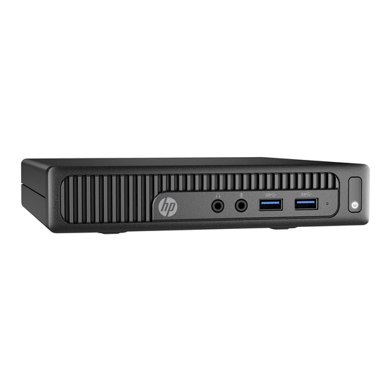
Page 10: Front Panel Components
Front panel components Drive configuration may vary by model. Front panel components Audio-out (headphone) jack Hard drive activity light Audio-in (microphone) jack Power button USB 3.0 ports NOTE: The Power On light is normally white when the power is on. If it is flashing red, there is a problem with the computer and it is displaying a diagnostic code. -
Page 11: Illustrated Parts Catalog
Chassis spare parts NOTE: HP continually improves and changes product parts. For complete and current information on supported parts for your computer, go to http://partsurfer.hp.com, select your country or region, and then follow the on-screen instructions. Computer major components Item... -
Page 12: Miscellaneous Parts
Item Description Heat sink Speaker Hard drive connector and cable WLAN module (HP WLAN 802.11 b/g/n 1x1 + Bluetooth 4.0) Hard drive cage Antennas and transceivers (not illustrated) Power supply, 65W, 89% efficiency (not illustrated) Stand (not illustrated) HP Ultraslim Keyed Cable Lock (not illustrated) -
Page 13: Drives And Memory
Item Description HP USB slim HP USB Essential HP wireless keyboard and mouse with dongle Power cord, 1.83 m; (not illustrated) Drives and memory Item Description Hard drive 1 TB, 5400 rpm hard drive, 2.5-inch 500 GB, 5400 rpm hard drive, 2.5-inch... -
Page 14: Routine Care, Sata Drive Guidelines, And Disassembly Preparation
Routine care, SATA drive guidelines, and disassembly preparation This chapter provides general service information for the computer. Adherence to the procedures and precautions described in this chapter is essential for proper service. CAUTION: When the computer is plugged into an AC power source, voltage is always applied to the system board. -
Page 15: Preventing Electrostatic Damage To Equipment
Preventing electrostatic damage to equipment Many electronic components are sensitive to ESD. Circuitry design and structure determine the degree of sensitivity. The following packaging and grounding precautions are necessary to prevent damage to electric components and accessories. ● To avoid hand contact, transport products in static-safe containers such as tubes, bags, or boxes. ●... -
Page 16: Recommended Materials And Equipment
Recommended materials and equipment Materials and equipment that are recommended for use in preventing static electricity include: ● Antistatic tape ● Antistatic smocks, aprons, or sleeve protectors Conductive bins and other assembly or soldering aids ● ● Conductive foam ● Conductive tabletop workstations with ground cord of one-megohm +/- 10% resistance ●... -
Page 17: Routine Care
● Never cover the ventilation slots on the monitor with any type of material. Install or enable power management functions of the operating system or other software, including ● sleep states. Routine care General cleaning safety precautions Never use solvents or flammable solutions to clean the computer. Never immerse any parts in water or cleaning solutions;... -
Page 18: Cleaning The Monitor
The screws used in the computer are not interchangeable. They may have standard or metric threads and may be of different lengths. If an incorrect screw is used during the reassembly process, it can damage the unit. HP strongly recommends that all screws removed during disassembly be kept with the part that was removed, then returned to their proper locations. -
Page 19: Hard Drives
Batteries, battery packs, and accumulators should not be disposed of together with the general household waste. In order to forward them to recycling or proper disposal, please use the public collection system or return them to HP, their authorized partners, or their agents. Service considerations... -
Page 20: Sata Hard Drives
6.0 Gb/s SATA hard drive cables SATA data cable Always use an HP approved SATA 6.0 Gb/s cable as it is fully backwards compatible with the SATA 1.5 Gb/s drives. Current HP desktop products ship with SATA 6.0 Gb/s hard drives. -
Page 21: Removal And Replacement Procedures
Not all features listed in this guide are available on all computers. NOTE: HP continually improves and changes product parts. For complete and current information on supported parts for your computer, go to http://partsurfer.hp.com, select your country or region, and then follow the on-screen instructions. Preparation for disassembly Routine care, SATA drive guidelines, and disassembly preparation on page 6 for initial safety procedures. -
Page 22: Access Panel
Access panel Prepare the computer for disassembly (Preparation for disassembly on page 13). Remove the screw on the rear of the computer (1), and then slide the panel forward and lift if off the computer (2). To install the access panel, reverse the removal procedure. Chapter 4 Removal and replacement procedures... -
Page 23: Hard Drive
Hard drive Description Hard drives 1 TB, 5400 rpm hard drive, 2.5-inch 500 GB, 5400 rpm hard drive, 2.5-inch Solid-state drives 256 GB 128 GB Grommet, hard drive NOTE: Before you remove the old hard drive, be sure to back up the data from the old hard drive so that you can transfer the data to the new hard drive. - Page 24 Remove the silver and blue isolation mounting guide screws from the sides of the old hard drive. Reverse this procedure to replace the hard drive. Chapter 4 Removal and replacement procedures...
-
Page 25: Memory
Memory Description 16-GB, PC4-17000, SODIMM 8-GB, PC4-17000, SODIMM 4-GB, PC4-17000, SODIMM 2-GB, PC4-17000, SODIMM The computer comes with at least one preinstalled double data rate 4 synchronous dynamic random access memory (DDR4-SDRAM) small outline dual inline memory module (SODIMM). There are two memory sockets on the system board that can be populated with up to 32 GB of memory. -
Page 26: Populating Sodimm Sockets
Populating SODIMM sockets There are two SODIMM sockets on the system board, with one socket per channel. The sockets are labeled DIMM1 and DIMM3. The DIMM1 socket operates in memory channel B. The DIMM3 socket operates in memory channel A. Item Description System Board Label... -
Page 27: Replacing Sodimms
Replacing SODIMMs CAUTION: You must disconnect the power cord and wait approximately 30 seconds for the power to drain before adding or removing memory modules. Regardless of the power-on state, voltage is always supplied to the memory modules as long as the computer is plugged into an active AC outlet. Adding or removing memory modules while voltage is present may cause irreparable damage to the memory modules or system board. - Page 28 Slide the new SODIMM into the socket at approximately a 30° angle (1) then press the SODIMM down (2) so that the latches lock it in place. NOTE: A memory module can be installed in only one way. Match the notch on the module with the tab on the memory socket.
-
Page 29: Wlan Module
WLAN module The WLAN module is located near from the front of the computer. The module is secured with one Phillips screw and has two connected antennas. The main antenna connects to a transceiver near the speaker assembly. The auxiliary antenna connects to a transceiver on the rear of the chassis. NOTE: WLAN module appearance may vary. -
Page 30: Speaker
Speaker A single speaker is located behind the front bezel. It is secured by one plastic pin. A wireless antenna transceiver mounts to the front of the speaker assembly. To remove the speaker: Prepare the computer for disassembly (Preparation for disassembly on page 13). - Page 31 Lift the speaker out of the computer (3) To install the speaker, reverse the removal procedures. Speaker...
-
Page 32: Fan
The fan sits atop the heat sink and is secured with two Torx screws. Prepare the computer for disassembly (Preparation for disassembly on page 13). Remove the access panel (Access panel on page 14). Disconnect the fan cable from the system board connector labeled CPUFAN (1). Remove the two Torx screws that secure the fan to the heat sink (2). -
Page 33: Rtc Battery
The lithium battery is only used when the computer is NOT connected to AC power. HP encourages customers to recycle used electronic hardware, HP original print cartridges, and rechargeable batteries. For more information about recycling programs, go to http://www.hp.com/recycle. - Page 34 To release the battery from its holder, pull back the metal clamp that extends above one edge of the battery (1). When the battery pops up, lift it out of the holder (2). To insert the new battery, make sure the positive side of the battery is facing up and slide one edge of the replacement battery under the metal clamp that was pulled back when removing the old battery.
-
Page 35: Heat Sink
Heat sink The heat sink is secured with four captive Torx screws. Be sure to remove and replace the screws in the order indicated on the heat sink. Prepare the computer for disassembly (Preparation for disassembly on page 13). Remove the access panel (Access panel on page 14). -
Page 36: Drive Cage And Drive Cable
Drive cage and drive cable The drive cage is located next to the heat sink and is secured with three Torx screws. The drive cable connects to the system board under in the drive cage. You have to remove the drive cage to access the drive cable connector underneath. - Page 37 Remove the drive cage from the computer to access the drive cable connector under the drive cage (2). Disconnect the drive connector cable from the SATA0 connector on the system board, and then remove the connector/cable from the computer. To install the drive cage and drive cable, reverse the removal procedures. Drive cage and drive cable...
-
Page 38: System Board
System board NOTE: All system board spare part kits include replacement thermal material. NOTE: System board appearance may vary. Description System board with embedded Intel Core i5-4210U processor System board with embedded Intel Core i3-4030U processor System board with embedded Intel Pentium 3558U processor System board with embedded Intel Celeron 2957U processor Prepare the computer for disassembly (Preparation for disassembly on page... - Page 39 Lift the front of the system board, and then pull the board away from the rear connectors to remove it from the computer (2). To install the system board, reverse the removal procedures. NOTE: When replacing the system board, you must change the chassis serial number in the BIOS. Updating SMBIOS Information When replacing the system board, you must reprogram the SMBIOS information on the affected computer.
- Page 40 System ID Setup Page Setup Field Name Comment Label Product Name Enter the Model name/number or Flexbuild marketing name. Serial Number Enter the Serial Number of Unit. Support SKU Number Enter the SKU or Product Number including Support Localization Code. Asset Tag Enter the 18-byte identifier assigned to the Support...
-
Page 41: System Board Callouts
System board callouts Sys Bd Label Color Component Sys Bd Label Color Component CMOS Yellow CMOS reset button SPKR White Speaker connector CPUFAN Black Fan connector PSWD Black/blue Password header and jumper DIMM3 Black Primary memory socket XBT1 Black RTC battery DIMM1 Black Secondary memory... -
Page 42: Wireless Antennas
Wireless antennas The antenna cables route from the WLAN module to antennas on the front near the speaker and on the rear of the chassis. To replace the antennas: Prepare the computer for disassembly (Preparation for disassembly on page 13). Remove the access panel (Access panel on page 14). - Page 43 Remove the antenna while routing the cable through the hole in the front of the computer. Remove the antenna cable from the clips in the bottom of the chassis. Wireless antennas...
- Page 44 Remove the cover from atop the rear antenna by pressing down on the tab at the top of the cover (1), and then rotating the cover off the computer (2). Remove the rear antenna by pressing the tab on the inside of the computer to disengage the antenna. Chapter 4 Removal and replacement procedures...
- Page 45 Remove the antenna while routing the cable through the hole in the rear of the computer. Reverse the removal procedure to install the wireless antennas. When installing wireless antennas, use the following images to determine how to properly route the cables into the chassis.
-
Page 46: Installing An Optional Rear Port Cover
Installing an optional rear port cover To install the optional rear port cover, connect the cables, and then insert the hooks on the port cover into the slots on the rear of the computer and slide the port cover to the right. Chapter 4 Removal and replacement procedures... -
Page 47: Computer Setup (F10) Utility
Computer Setup (F10) Utility Computer Setup (F10) Utilities Use Computer Setup (F10) Utility to do the following: ● Change factory default settings. Set the system date and time. ● ● Set, view, change, or verify the system configuration, including settings for processor, graphics, memory, audio, storage, communications, and input devices. -
Page 48: Using Computer Setup (F10) Utilities
Using Computer Setup (F10) Utilities Computer Setup can be accessed only by turning the computer on or restarting the system. To access the Computer Setup Utilities menu, complete the following steps: Turn on or restart the computer. Repeatedly press when the monitor light turns green to access the utility. You can also press to a menu that allows you to access different options available at startup, including the Computer Setup utility. -
Page 49: Computer Setup-File
Computer Setup—File NOTE: Support for specific Computer Setup options may vary depending on the hardware configuration. Table 5-1 Computer Setup—File Option Description System Information Lists: ● Manufacturer ● Product name ● SKU number ● Serial number ● Born on Date ●... -
Page 50: Computer Setup-Storage
Computer Setup—Storage NOTE: Support for specific Computer Setup options may vary depending on the hardware configuration. Table 5-2 Computer Setup—Storage Option Description Device Configuration Lists all installed BIOS-controlled storage devices. When a device is selected, detailed information and options are displayed. The following options may be presented: ●... -
Page 51: Computer Setup-Security
Computer Setup—Security NOTE: Support for specific Computer Setup options may vary depending on the hardware configuration. Table 5-3 Computer Setup—Security Option Description Setup Password Allows you to set and enable a setup (administrator) password. NOTE: If the setup password is set, it is required to change Computer Setup options, flash the ROM, and make changes to certain plug and play settings under Windows. - Page 52 (PK) that verifies kernels during system start up, allowing you to use alternative operating systems. Selecting HP Keys causes the computer boot using the preloaded HP-specific boot keys. Default is HP Keys.
-
Page 53: Computer Setup-Power
Computer Setup—Power NOTE: Support for specific Computer Setup options may vary depending on the hardware configuration. Table 5-4 Computer Setup—Power Option Description OS Power Management Runtime Power Management—Enable/Disable. Allows certain operating systems to reduce ● processor voltage and frequency when the current software load does not require the full capabilities of the processor. -
Page 54: Recovering The Configuration Settings
Table 5-5 Computer Setup—Advanced (for advanced users) (continued) Option Description Select the Legacy device's IRQ, DMA, and I/O Range. The settings may not take effect for all operating systems. To hide a device from the operating system, see Security > Device Security. Bus Options Allows you to enable or disable: ●... -
Page 55: Troubleshooting Without Diagnostics
To assist you in resolving problems online, HP Instant Support Professional Edition provides you with self- solve diagnostics. If you need to contact HP support, use HP Instant Support Professional Edition's online chat feature. Access HP Instant Support Professional Edition at: http://www.hp.com/go/ispe. -
Page 56: Helpful Hints
If it becomes necessary to call for technical assistance, be prepared to do the following to ensure that your service call is handled properly: Be in front of your computer when you call. ● ● Write down the computer serial number, product ID number, and monitor serial number before calling. ●... -
Page 57: Solving General Problems
● If you have installed an operating system other than the factory-installed operating system, check to be sure that it is supported on the system. ● If the system has multiple video sources (embedded, PCI, or PCI-Express adapters) installed (embedded video on some models only) and a single monitor, the monitor must be plugged into the monitor connector on the source selected as the primary VGA adapter. - Page 58 In case of forgotten password, power loss, or computer malfunction, you must manually disable the Smart Cover lock . A key to unlock the Smart Cover Lock is not available from HP. Keys are typically available from a hardware store.
- Page 59 Poor performance. Cause Solution Low on memory. Add more memory. Hard drive fragmented. Defragment hard drive. Program previously accessed did not release reserved memory Restart the computer. back to the system. Virus resident on the hard drive. Run virus protection program. Too many applications running.
- Page 60 System does not power on and the LEDs on the front of the computer are not flashing. Cause Solution System unable to power on. Press and hold the power button for less than 4 seconds. If the hard drive LED turns white, then: If equipped with a voltage selector, check that the voltage selector (located on the rear of the power supply) is set to the appropriate voltage.
-
Page 61: Solving Power Problems
Solving power problems Common causes and solutions for power problems are listed in the following table. Power supply shuts down intermittently. Cause Solution If equipped with a voltage selector, voltage selector switch on Select the proper AC voltage using the selector switch. rear of computer chassis (some models) not switched to correct line voltage (115V or 230V). -
Page 62: Solving Hard Drive Problems
Solving hard drive problems Hard drive error occurs. Cause Solution Hard disk has bad sectors or has failed. In Windows 7, click Start, click Computer, and right-click on a drive. Select Properties, and then select the Tools tab. Under Error-checking click Check Now. In Windows 10, type file in the taskbar search box, and then select File Explorer from the list of applications. - Page 63 Nonsystem disk/NTLDR missing message. Cause Solution The system is trying to start from the hard drive but the hard ▲ Perform Drive Protection System (DPS) testing in system drive may have been damaged. ROM. System files missing or not properly installed. Insert bootable media and restart the computer.
-
Page 64: Solving Media Card Reader Problems
Solving media card reader problems Media card will not work in a digital camera after formatting it in Windows. Cause Solution By default, Windows will format any media card with a capacity Either format the media card in the digital camera or select FAT greater than 32MB with the FAT32 format. -
Page 65: Solving Display Problems
After installing the media card reader and booting to Windows, the reader and the inserted cards are not recognized by the computer. Cause Solution The operating system needs time to recognize the device if the Wait a few seconds so that the operating system can recognize reader was just installed into the computer and you are turning the reader and the available ports, and then recognize the media the PC on for the first time. - Page 66 Reseat DIMMs. Power on the system. Replace DIMMs one at a time to isolate the faulty module. Replace third-party memory with HP memory. Replace the system board. Blank screen and the power LED flashes Red six times, once every second, followed by a two second pause, and the computer beeps six times.
- Page 67 Monitor does not function properly when used with energy saver features. Cause Solution Monitor without energy saver capabilities is being used with Disable monitor energy saver feature. energy saver features enabled. Dim characters. Cause Solution The brightness and contrast controls are not set properly. Adjust the monitor brightness and contrast controls.
- Page 68 “No Connection, Check Signal Cable” displays on screen. Cause Solution Monitor video cable is disconnected. Connect the video cable between the monitor and computer. CAUTION: Ensure that the computer power is off while connecting the video cable. “Out of Range” displays on screen. Cause Solution Video resolution and refresh rate are set higher than what the...
-
Page 69: Solving Audio Problems
Solution with the synchronization, go to the following Web site, select the appropriate monitor, and download either SP32347 or SP32202: http://www.hp.com/support Graphics card is not seated properly or is bad (some models). Reseat the graphics card. Replace the graphics card. - Page 70 Sound does not come out of the speaker or headphones. Cause Solution Headphones or devices connected to the line-out connector mute Turn on and use headphones or external speakers, if connected, the internal speaker. or disconnect headphones or external speakers. Computer is in Sleep state.
-
Page 71: Solving Printer Problems
There is no sound or sound volume is too low. Cause Solution The application is set to use a different audio device than Some graphics cards support audio over the DisplayPort speakers. connection (if applicable), so multiple audio devices may be listed in Device Manager. -
Page 72: Solving Keyboard And Mouse Problems
Printer prints garbled information. Cause Solution The correct printer driver for the application is not installed. Install the correct printer driver for the application. The cables may not be connected properly. Reconnect all cables. Printer memory may be overloaded. Reset the printer by turning it off for one minute, then turn it back Printer will not print. -
Page 73: Solving Hardware Installation Problems
Mouse does not respond to movement or is too slow. Cause Solution Mouse connector is not properly plugged into the back of the Shut down the computer using the keyboard. computer. Windows 7: Press the Ctrl keys at the same time (or press the Windows logo key) to display the Start menu. - Page 74 WARNING! When the computer is plugged into an AC power source, voltage is always applied to the system board. To reduce the risk of personal injury from electrical shock and/or hot surfaces, be sure to disconnect the power cord from the wall outlet and allow the internal system components to cool before touching. Table 6-1 Solving Hardware Installation Problems A new device is not recognized as part of the system.
-
Page 75: Solving Network Problems
DIMM1 or XMM1 must always be installed. DIMM1 must be installed before DIMM2, and DIMM3 must be installed before DIMM4 Replace third-party memory with HP memory. Replace the system board. Solving Network Problems Some common causes and solutions for network problems are listed in the following table. These guidelines do not discuss the process of debugging the network cabling. - Page 76 Table 6-2 Solving Network Problems (continued) Network status link light never flashes. NOTE: The network status light is supposed to flash when there is network activity. Cause Solution To access Device Manager in Windows 10, type device manager in the taskbar search box, and then select Device Manager from the list of applications.
- Page 77 Network controller stopped working when an expansion board was added to the computer. Cause Solution The network controller requires drivers. Verify that the drivers were not accidentally deleted when the drivers for a new expansion board were installed. Network controller stops working without apparent cause. Cause Solution The files containing the network drivers are corrupted.
-
Page 78: Solving Memory Problems
Management Engine (ME) settings). To avoid damage to the DIMMs or the system board, you must unplug the computer power cord before attempting to reseat, install, or remove a memory module. For those systems that support ECC memory, HP does not support mixing ECC and non-ECC memory. Otherwise, the computer will not boot the operating system. -
Page 79: Solving Usb Flash Drive Problems
Memory is installed incorrectly or is bad. Reseat DIMMs. Power on the system. Replace DIMMs one at a time to isolate the faulty module. Replace third-party memory with HP memory. Replace the system board. Solving USB flash drive problems If you encounter USB flash drive problems, common causes and solutions are listed in the following table. -
Page 80: Solving Front Panel Component Problems
Solving front panel component problems If you encounter problems with devices connected to the front panel, refer to the common causes and solutions listed in the following table. A USB device, headphone, or microphone is not recognized by the computer. Cause Solution Device is not properly connected. - Page 81 Unable to connect to the Internet. Cause Solution In the Browsing history section on the General tab, click the Delete button. Select the Cookies check box and click the Delete button. Windows 10: Type control panel in the taskbar search box, and then select Control Panel from the list of applications.
-
Page 82: Solving Software Problems
If you have installed an operating system other than the factory-installed operating system, check to be sure it is supported on the system. If you encounter software problems, see the applicable solutions listed in the following table. Computer will not continue and the HP logo does not display. Cause Solution ROM issue - POST error has occurred. -
Page 83: Post Error Messages And Diagnostic Front Panel Leds And Audible Codes
POST error messages and diagnostic front panel LEDs and audible codes This appendix lists the error codes, error messages, and the various indicator light and audible sequences that you may encounter during Power-On Self-Test (POST) or computer restart, the probable source of the problem, and steps you can take to resolve the error condition. - Page 84 Control panel message Description Recommended action RTC (real-time clock) battery may need to problem persists, replace the RTC battery. See be replaced. the Removal and Replacement section for instructions on installing a new battery. 008–Microcode Patch Error Processor is not supported by the BIOS. Upgrade BIOS to proper version.
- Page 85 Run the Drive Protection erroneous error message.) System test under using F2 Diagnostics when booting the computer. Apply hard drive firmware patch if applicable. (Available at http://www.hp.com/support.) POST numeric codes and text messages...
- Page 86 System test under using F2 Diagnostics when booting the computer. Apply hard drive firmware patch if applicable. (Available at http://www.hp.com/support.) Back up contents and replace hard drive. 309 – 30C: Hard Disk 3–6: SMART Hard Drive Hard drive is about to fail. (Some hard drives...
- Page 87 Control panel message Description Recommended action Reconfigure card resources and/or run Computer Setup or Windows utilities. 419-Out of Memory Space for Option ROMs Recently added PCI expansion card contains an If a PCI expansion card was recently ▲ option ROM too large to download during POST. added, remove it to see if the problem remains.
-
Page 88: Interpreting System Validation Diagnostic Front Panel Leds And Audible Codes
Control panel message Description Recommended action 90B-Fan Failure The system has detected that a cooling fan is Reseat fan. not operating correctly. Reseat fan cable. Replace fan. 90D-System Temperature Thermal shutdown occurred. The system BIOS Make sure system has proper airflow. has detected your machine was previously shut down to avoid overheating. - Page 89 Number of long beeps/blinks Error category Thermal System board Patterns of blink/beep codes are determined by using the following parameters: ● 1 second pause occurs after the last major blink. ● 2 second pause occurs after the last minor blink. ●...
-
Page 90: Password Security And Resetting Cmos
If you lose or forget the password when in stringent security mode, the system can only be reset by System Management Command. This is a way for HP Service and Support to provide a secure method to access the BIOS and command a password reset for a specifically identified unit under the direction of the owner. This scenario may not be covered under warranty. - Page 91 Shut down the operating system properly, then turn off the computer and any external devices, and disconnect the power cord from the power outlet. With the power cord disconnected, press the power button again to drain the system of any residual power.
-
Page 92: Clearing And Resetting The Bios
Clearing and resetting the BIOS The CMOS button resets BIOS settings to default, but does not clear the passwords or affect any of the other Security settings. On Intel systems with advanced manageability features, the CMOS button will also partially unprovision AMT. - Page 93 Reconnect the external devices. Plug in the computer and turn on power. NOTE: You will receive POST error messages after clearing CMOS and rebooting advising you that configuration changes have occurred. Use Computer Setup to reset any special system setups along with the date and time.
-
Page 94: Using Hp Pc Hardware Diagnostics (Uefi)
Using HP PC Hardware Diagnostics (UEFI) HP PC Hardware Diagnostics is a Unified Extensible Firmware Interface (UEFI) that allows you to run diagnostic tests to determine whether the computer hardware is functioning properly. The tool runs outside the operating system so that it can isolate hardware failures from issues that are caused by the operating system or other software components. - Page 95 Select your computer, and then select your operating system. In the Diagnostic section, follow the on-screen instructions to select and download the UEFI version you want. Downloading HP PC Hardware Diagnostics (UEFI) to a USB device...
-
Page 96: 10 System Backup And Recovery
Use HP Recovery Manager to create HP Recovery media after you successfully set up the computer. This ● step creates a backup of the HP Recovery partition on the computer. The backup can be used to reinstall the original operating system in cases where the hard drive is corrupted or has been replaced. For... -
Page 97: Using Windows Tools
DVD-R, DVD+R, DVD-R DL, or DVD+R DL discs. Do not use rewritable discs such as CD±RW, DVD±RW, double-layer DVD±RW, or BD-RE (rewritable Blu-ray) discs; they are not compatible with HP Recovery Manager software. Or, instead, you can use a high- quality blank USB flash drive. -
Page 98: Recovering Using Hp Recovery Manager
Creating HP Recovery media (select products only) on page ● If your computer does not allow the creation of HP Recovery media or if the HP Recovery media does not work, you can obtain recovery media for your system from support. See the Worldwide Telephone Numbers booklet included with the computer. -
Page 99: Using The Hp Recovery Partition (Select Products Only)
Using HP Recovery media to recover You can use HP Recovery media to recover the original system. This method can be used if your system does not have an HP Recovery partition or if the hard drive is not working properly. -
Page 100: Backing Up, Restoring, And Recovering In Windows 7
IMPORTANT: After you remove the HP Recovery partition, you will not be able to perform System Recovery or create HP recovery media from the HP Recovery partition. So before you remove the Recovery partition, create HP Recovery media; see Creating HP Recovery media (select products only) on page NOTE: The Remove Recovery Partition option is only available on products that support this function. -
Page 101: Creating Recovery Media Using Hp Recovery Manager (Select Models Only)
Click the Start button, click All Programs, click Security and Protection, click Recovery Manager, and then click HP Recovery Media Creation. If prompted, click Yes to allow the program to continue. Click Create recovery media using blank DVD(s), and then click Next. -
Page 102: Creating Recovery Discs With Hp Recovery Disc Creator (Select Models Only)
Creating recovery discs with HP Recovery Disc Creator (select models only) HP Recovery Disc Creator is a software program that offers an alternative way to create recovery discs on select models. After you successfully set up the computer, you can create recovery discs using HP Recovery Disc Creator. -
Page 103: System Restore
If you were not able to create system recovery DVDs or USB flash drive, you can order a recovery disc set from support. Go to http://www.hp.com/support, select your country or region, and follow the on-screen instructions. -
Page 104: System Recovery When Windows Is Responding
Disconnect all peripheral devices from the computer, except the monitor, keyboard, and mouse. Press the power button to turn on the computer. As soon as you see the HP logo screen, repeatedly press the key on your keyboard until the Windows is Loading Files…... -
Page 105: System Recovery Using Recovery Media (Select Models Only)
Using HP Recovery Disc operating system discs (select models only) Use the steps provided in this section if you used HP Recovery Disc Creator to create a Windows 7 operating system DVD and a Driver Recovery DVD. If you created recovery media using... - Page 106 To order a Windows 7 operating system DVD, contact support. Go to http://www.hp.com/support, select your country or region, and follow the on-screen instructions. CAUTION: Using a Windows 7 operating system DVD completely erases the hard drive contents and reformats the hard drive. All files that you have created and any software that you have installed on the computer are permanently removed.
-
Page 107: Appendix A Power Cord Set Requirements
Power Cord Set Requirements The power supplies on some computers have external power switches. The voltage select switch feature on the computer permits it to operate from any line voltage between 100-120 or 220-240 volts AC. Power supplies on those computers that do not have external power switches are equipped with internal switches that sense the incoming voltage and automatically switch to the proper voltage. -
Page 108: Country-Specific Requirements
Country-Specific Requirements Additional requirements specific to a country are shown in parentheses and explained below. Country Accrediting Agency Country Accrediting Agency Australia (1) EANSW Italy (1) Austria (1) Japan (3) METI Belgium (1) CEBC Norway (1) NEMKO Canada (2) Sweden (1) SEMKO Denmark (1) DEMKO... -
Page 109: Appendix B Statement Of Volatility
Follow the instructions to flash the BIOS that are found on the website. Flashing the BIOS will reset it back to factory settings. Turn on the system, and while system is powering on, and after the HP splash screen, press the to enter BIOS setup screen. - Page 110 To clear the Setup or Power-On passwords if set, and clear any other settings, power down the computer and remove the AC power cord and the computer hood. Locate the green/blue two pin password jumper on header E49 (labeled PSWD) and remove it. Remove the AC power, wait 10 seconds until the unit AC power has drained out, then press the clear CMOS button.
-
Page 111: Appendix C Specifications
Specifications Table C-1 Specifications Dimensions (with stand) 6.9 in 175 mm Height 7.0 in 177 mm Width 1.3 in 34 mm Depth Approximate Weight 2.3 lb 1.05 kg Temperature Range 41° to 95°F 5° to 35°C Operating -22° to 149°F -30°... -
Page 112: Index
25 HP PC Hardware Diagnostics (UEFI) codes 75, 80 battery replacement 25 downloading 86 messages 75 beep codes 80 HP Recovery Disc Creator, using 94 BIOS clearing and resetting 84 F10 Setup booting options installing access problem 49... - Page 113 socket population 18 recovery discs, steps for creating specifications specifications 17 Windows 7 93 computer 103 monitor problems 57 recovery discs, using for restore 97 static electricity 6 mouse recovery media, creating 94 system board cleaning 10 recovery media, creating Windows illustrated 3 problems 64 7 92...
- Page 114 Windows 7 operating system media creating 94 WLAN antennas removal and replacement 34 WLAN module illustrated 4 removal and replacement 21 106 Index...
Need help?
Do you have a question about the 260 G2 and is the answer not in the manual?
Questions and answers