Table of Contents
Advertisement
Quick Links
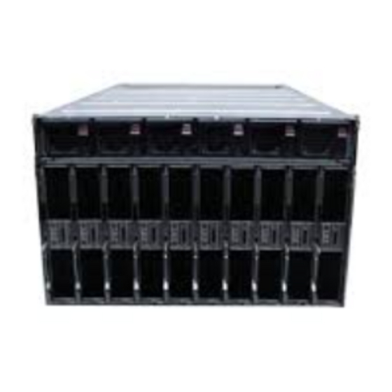
HPE Apollo a6000 Chassis
Maintenance and Service Guide
Abstract
This guide is for an experienced service technician. Hewlett Packard Enterprise assumes you are qualified in the servicing of computer
equipment and trained in recognizing hazards in products with hazardous energy levels and are familiar with weight and stability
precautions for rack installations.
Part Number: 752045-002R
November 2015
Edition: 3
Advertisement
Table of Contents
Troubleshooting

Related Manuals for HP Apollo a6000 Chassis


Summary of Contents for HP Apollo a6000 Chassis
- Page 1 HPE Apollo a6000 Chassis Maintenance and Service Guide Abstract This guide is for an experienced service technician. Hewlett Packard Enterprise assumes you are qualified in the servicing of computer equipment and trained in recognizing hazards in products with hazardous energy levels and are familiar with weight and stability precautions for rack installations.
- Page 2 © Copyright 2014, 2015 Hewlett Packard Enterprise Development LP The information contained herein is subject to change without notice. The only warranties for Hewlett Packard Enterprise products and services are set forth in the express warranty statements accompanying such products and services. Nothing herein should be construed as constituting an additional warranty.
-
Page 3: Table Of Contents
Contents Customer self repair ..........................5 Parts only warranty service ............................5 Illustrated parts catalog ........................15 Chassis system and mechanical components ....................... 15 Power shelf components ............................17 Removal and replacement procedures ....................20 Required tools ................................ 20 Preparation procedures ............................20 Power down the server .......................... - Page 4 Loose connections............................53 Service notifications............................. 53 Power cycle the HPE Apollo a6000 Chassis ....................53 Server does not power on when power is applied to the chassis or when the server is installed into a chassis that has power applied ..........................54 Specifications ............................
-
Page 5: Customer Self Repair
Customer self repair Hewlett Packard Enterprise products are designed with many Customer Self Repair (CSR) parts to minimize repair time and allow for greater flexibility in performing defective parts replacement. If during the diagnosis period Hewlett Packard Enterprise (or Hewlett Packard Enterprise service providers or service partners) identifies that the repair can be accomplished by the use of a CSR part, Hewlett Packard Enterprise will ship that part directly to you for replacement. - Page 6 • Obligatoire—Pièces pour lesquelles la réparation par le client est obligatoire. Si vous demandez à Hewlett Packard Enterprise de remplacer ces pièces, les coûts de déplacement et main d'œuvre du service vous seront facturés. • Facultatif—Pièces pour lesquelles la réparation par le client est facultative. Ces pièces sont également conçues pour permettre au client d'effectuer lui-même la réparation.
- Page 7 NOTA: alcuni componenti Hewlett Packard Enterprise non sono progettati per la riparazione da parte del cliente. Per rispettare la garanzia, Hewlett Packard Enterprise richiede che queste parti siano sostituite da un centro di assistenza autorizzato. Tali parti sono identificate da un "No" nel Catalogo illustrato dei componenti.
- Page 8 Support Center anrufen und sich von einem Mitarbeiter per Telefon helfen lassen. Den Materialien von Hewlett Packard Enterprise, die mit einem CSR-Ersatzteil geliefert werden, können Sie entnehmen, ob das defekte Teil an Hewlett Packard Enterprise zurückgeschickt werden muss. Wenn es erforderlich ist, das defekte Teil an Hewlett Packard Enterprise zurückzuschicken, müssen Sie dies innerhalb eines vorgegebenen Zeitraums tun, in der Regel innerhalb von fünf (5) Geschäftstagen.
- Page 9 deberá hacerlo en el periodo de tiempo especificado, normalmente cinco días laborables. Los componentes defectuosos deberán devolverse con toda la documentación relacionada y con el embalaje de envío. Si no enviara el componente defectuoso requerido, Hewlett Packard Enterprise podrá cobrarle por el de sustitución.
- Page 10 Enterprise u voor het vervangende onderdeel kosten in rekening brengen. Bij reparatie door de klant betaalt Hewlett Packard Enterprise alle verzendkosten voor het vervangende en geretourneerde onderdeel en kiest Hewlett Packard Enterprise zelf welke koerier/transportonderneming hiervoor wordt gebruikt. Neem contact op met een Service Partner voor meer informatie over het Customer Self Repair programma van Hewlett Packard Enterprise.
- Page 11 Para obter mais informações sobre o programa de reparo feito pelo cliente da Hewlett Packard Enterprise, entre em contato com o fornecedor de serviços local. Para o programa norte-americano, visite o site da Hewlett Packard Enterprise (http://www.hpe.com/support/selfrepair). Serviço de garantia apenas para peças A garantia limitada da Hewlett Packard Enterprise pode incluir um serviço de garantia apenas para peças.
- Page 12 Customer self repair 12...
- Page 13 Customer self repair 13...
- Page 14 Customer self repair 14...
-
Page 15: Illustrated Parts Catalog
Power management cable assembly* 747038-001 Mandatory Mandatory HPE Apollo a6000 Chassis Rail kit* 747036-001 *Not shown **For more information about the I/O module option spare parts, see the server maintenance and service guide on the Hewlett Packard Enterprise website (http://www.hpe.com/info/Apollo_6000/docs). - Page 16 Non—Certaines pièces Hewlett Packard Enterprise ne sont pas conçues pour être remplacées par le client. Afin de se conformer aux exigences de la garantie la garantie du client, Hewlett Packard Enterprise demande à un fournisseur de services agréé de procéder au remplacement de la pièce. Ces pièces sont signaléespar le mot « Non »...
-
Page 17: Power Shelf Components
Power shelf components Item Description Spare part number Customer self repair (on page 5) — Power shelf — Power management module 747329-001 Mandatory AC input module — — Mandatory a) Single-phase module 413494-001 b) Three-phase module 413495-001 Mandatory Illustrated parts catalog 17... - Page 18 Item Description Spare part number Customer self repair (on page 5) c) Three-phase module (non-US) 413496-001 Mandatory — Power supplies — a) 2450W Platinum Power Supply 588733-001 Mandatory Mandatory b) 2650W Platinum Power Supply 733830-001 Power cables — — a) DC, 116.84 cm (46.00 in) 746090-001 Mandatory b) DC, 98.43 cm (38.75 in)
- Page 19 Obligatorio—Componentes cuya reparación por parte del usuario es obligatoria. Si solicita a Hewlett Packard Enterprise que realice la sustitución de estos componentes, tendrá que hacerse cargo de los gastos de desplazamiento y de mano de obra de dicho servicio. Opcional—Componentes cuya reparación por parte del usuario es opcional. Estos componentes también están diseñados para que puedan ser reparados por el usuario.
-
Page 20: Removal And Replacement Procedures
Removal and replacement procedures Required tools You need the following items for some procedures: • T-10 Torx screwdriver • T-15 Torx screwdriver Preparation procedures To access some components and perform certain service procedures, you might need to perform one or more of the following procedures: •... -
Page 21: Remove The Management Module
IMPORTANT: When removing a server from an even numbered bay that remains unoccupied by another server for an extended period of time, the performance of the server installed in the bay to the immediate left may be impacted. Power down the server (on page 20). Disconnect all peripheral cables from the server. -
Page 22: Remove The Chassis From The Rack
Remove the management module. Remove the chassis from the rack WARNING: The chassis is very heavy. To reduce the risk of personal injury or damage to the equipment: • Always use either a lift that can handle the load of the product or at least four people to lift and stabilize the product pieces during assembly, installation, or removal, especially when the chassis is not installed in the rack. -
Page 23: Install The Service Tray
Remove the screws that secure the chassis to the rail. Remove the chassis from the rack. Place the chassis on a flat surface. Install the service tray CAUTION: To prevent improper cooling and thermal damage, operate servers only when the open side of the server is enclosed by either another server, a divider, or the chassis wall. -
Page 24: Install The Chassis Into The Rack
Install the component as indicated. Install the chassis into the rack WARNING: The chassis is very heavy. To reduce the risk of personal injury or damage to the equipment, do the following: • Observe local occupational health and safety requirements and guidelines for manual material handling. - Page 25 CAUTION: Hewlett Packard Enterprise has not tested or validated the Apollo a6000 Chassis with any third-party racks. Before installing the Apollo a6000 Chassis in a third-party rack, be sure to properly scope the limitations of the rack. Before proceeding with the installation, consider the following: •...
-
Page 26: Installing A Server
Installing a server CAUTION: To prevent improper cooling and thermal damage, operate servers only when the open side of the server is enclosed by either another server, a divider, or the chassis wall. When installing servers in the chassis, observe the following guidelines to ensure proper air flow: •... -
Page 27: Installing The Power Shelf
Installing the power shelf CAUTION: To prevent damage to the component, power down the chassis and disconnect all power cords before removing or installing the component. To install the component: Install the power shelf rack rails into the rack. For more information, see the HPE Apollo 6000 Power Shelf Rack Rail in HPE Racks Installation Instructions. - Page 28 Install the power supplies into the power shelf, if needed. NOTE: If additional clearance is required to install power cables, loosen the thumb screw on either side of the shelf and slide the shelf out while installing the cables. Use caution to avoid bending the shelf.
- Page 29 Slide the cables toward the center, allowing them to straighten and hang from the rear of the power shelf. Install the cable guard. NOTE: Cables are removed for clarity. Removal and replacement procedures 29...
-
Page 30: Safety Considerations
Install the power supply vent cover to protect the power supply vents. Safety considerations Before performing service procedures, review all the safety information. Preventing electrostatic discharge To prevent damaging the system, be aware of the precautions you need to follow when setting up the system or handling parts. -
Page 31: Warnings And Cautions
This symbol on an RJ-45 receptacle indicates a network interface connection. WARNING: To reduce the risk of electric shock, fire, or damage to the equipment, do not plug telephone or telecommunications connectors into this receptacle. This symbol indicates the presence of a hot surface or hot component. If this surface is contacted, the potential for injury exists. -
Page 32: I/O Module
• Each fan contains two rotors. If one rotor fails, the fan is degraded and continues to operate. The health LED on the degraded fan changes to red and a management event is logged. The chassis can operate normally with one degraded fan (one failed rotor) until that fan is replaced. •... -
Page 33: Management Module
Remove the I/O module. To replace the component, reverse the removal procedure. Management module IMPORTANT: Always complete the installation of both power cages before installing the management module. To remove the component: Power down all servers ("Power down the server" on page 20). Remove the management module. -
Page 34: Power Cage
Power cage To remove the component: Power down all servers ("Power down the server" on page 20). Remove the management module ("Management module LEDs and buttons" on page 45, "Management module" on page 33). Remove the power cage. To replace the component, reverse the removal procedure. Power backplane To remove the component: Power down all servers... -
Page 35: Power Shelf Procedures
Remove the chassis rear cage. Remove the power backplane. To replace the component, reverse the removal procedure. Power shelf procedures This section provides removal and replacement procedures for power shelf components. Removal and replacement procedures 35... -
Page 36: Power Supplies
Power supplies Remove the component as indicated. To replace the component, reverse the removal procedure. Power cable retention brackets (left and right) Remove the component as indicated. To replace the component, reverse the removal procedure. Power management module To remove the component: Power down servers installed in the chassis connected to the power shelf ("Power down the server"... -
Page 37: Ac Input Module
Remove the power management module. To replace the component, reverse the removal procedure. AC input module To remove the component: Power down servers installed in the chassis connected to the power shelf ("Power down the server" on page 20). Remove the AC power cables. Remove the safety guard. - Page 38 Remove the AC input module. To replace the component, reverse the removal procedure. Removal and replacement procedures 38...
-
Page 39: Diagnostic Tools
Diagnostic tools Troubleshooting resources The HPE ProLiant Gen9 Troubleshooting Guide, Volume I: Troubleshooting provides procedures for resolving common problems and comprehensive courses of action for fault isolation and identification, issue resolution, and software maintenance on ProLiant servers and server blades. To view the guide, select a language: •... -
Page 40: Hpe Insight Diagnostics
• From within the iLO web interface • From within HPE Insight Diagnostics (on page 40) HPE Insight Diagnostics The Insight Diagnostics is a proactive server management tool, available in both offline and online versions, that provides diagnostics and troubleshooting capabilities to assist IT administrators who verify server installations, troubleshoot problems, and perform repair validation. -
Page 41: Hpe Smart Storage Administrator
HPE Smart Storage Administrator The HPE SSA is a configuration and management tool for HPE Smart Array controllers. Starting with HPE ProLiant Gen8 servers, HPE SSA replaces ACU with an enhanced GUI and additional configuration features. The HPE SSA exists in three interface formats: the HPE SSA GUI, the HPE SSA CLI, and HPE SSA Scripting. -
Page 42: Component Identification
Component identification Server tray bay numbering Rear panel components Item Description I/O modules (10) Fan assemblies (5) Power cage (Right) Management module Power cage (Left) Component identification 42... -
Page 43: Fan Assembly Bay Numbering
Fan assembly bay numbering The chassis has five fan assemblies located in the rear of the chassis. The following figure identifies the fan assemblies by device number. Fan LED Status Description The fan is working or the power is off. The fan has failed. -
Page 44: Management Module Components
Having both ports connected at the same time results in a loopback condition. IMPORTANT: If you have an APM connected to an Apollo a6000 Chassis, do not connect the iLO port of the APM and the iLO port of the enclosure to the network at the same time. Having both ports connected at the same time results in a loopback condition. -
Page 45: Management Module Leds And Buttons
Management module LEDs and buttons Item Description UID LED iLO network 1 link LED iLO network 1 activity LED iLO network 2 link LED iLO network 2 activity LED I/O module bay numbering I/O modules are specific to each server and are installed in the rear of the chassis. The chassis has ten I/O module bays located in the rear of the chassis. -
Page 46: Power Supply Leds
NOTE: The single-phase power shelf is shown below. A three-phase power shelf is also available. Item Description Power management connectors (6) APM module connector (PDM) AC input module power connectors (6) Power supply LEDs Power LED 1 Fault LED 2 Condition (green) (amber) -
Page 47: Cabling
Cabling Cabling overview WARNING: Be sure that all circuit breakers are locked in the off position before connecting any power components. CAUTION: To avoid damaging the fiber cables, do not drape cables from one side of the rack to the other and do not run cables over a hard corner or edge. CAUTION: To avoid damaging the cable, squeeze the thermal boot on the cable before disconnecting from the connector. - Page 48 Connect the power management cable to the power shelf with the cable's plastic tab facing up. CAUTION: To prevent damage to the power management cable, release the cable by pressing the latches when disconnecting, instead of pulling directly. IMPORTANT: When connecting the power management cable to the chassis management module and the power shelf, be sure to install the cable with the plastic tab on the top of the connector.
- Page 49 • Connecting three chassis to one power shelf Cabling 49...
-
Page 50: Example Configurations
• Connecting four chassis to one power shelf Cable quantity and length are determined by the configuration of components. For more information, see the Hewlett Packard Enterprise Power Advisor (http://www.hpe.com/info/hpepoweradvisor). Example configurations Configuration examples can be calculated using the Hewlett Packard Enterprise Power Advisor Tool (http://www.hpe.com/info/hpepoweradvisor). -
Page 51: Connecting Power Cables And Applying Power To The Chassis
Connect the APM to the power shelf (shown in blue). IMPORTANT: If you have an APM connected to an Apollo a6000 Chassis, do not connect the iLO port of the APM and the iLO port of the enclosure to the network at the same time. Having both ports connected at the same time results in a loopback condition. - Page 52 Connect the AC power cables to the power source (UPS or wall outlet) or to an installed PDU. Cabling 52...
-
Page 53: Troubleshooting
(http://www.hpe.com/info/hpesc). Enter the product name or number, and then click Go. Select Advisories, Bulletins & Notices. The complete list of documents is displayed. Power cycle the HPE Apollo a6000 Chassis Many issues that require troubleshooting will require that the power be removed and re-applied to the chassis. -
Page 54: Server Does Not Power On When Power Is Applied To The Chassis Or When The Server Is Installed Into A Chassis That Has Power Applied
Disengage the server from the chassis. The server can remain in the bay, but must be disengaged from the backplane. After all servers are disengaged, remove the management module ("Management module LEDs and buttons" on page 45, "Management module" on page 33). Remove both power cages ("Power cage"... - Page 55 Observe the entire chassis for at least 25 minutes. Check to see if all of the servers within the chassis reboot at the same time at some point within the 25 minute window.If not, proceed as follows. Power cycle the Apollo a6000 Chassis ("Power cycle the HPE Apollo a6000 Chassis" on page 53).
-
Page 56: Specifications
Specifications Chassis specifications Specification Value 22.02 cm (8.67 in) Height 86.23 cm (33.95 in) Depth 44.81 cm (17.64 in) Width 97.98 kg (216.00 lb) Weight, fully loaded 25.85 kg (57.00 lb) Weight, empty Chassis environmental specifications Specification Value — Temperature range* 10°C to 35°C (50°F to 95°F) Operating -30°C to 60°C (-22°F to... -
Page 57: Hot-Plug Power Supply Calculations
For hot-plug power supply specifications and calculators to determine electrical and heat loading for the server, see the Hewlett Packard Enterprise Power Advisor website (http://www.hpe.com/info/rackandpower). Power specifications The power requirements for the Apollo a6000 Chassis are met by the following components: • HPE 2450W Platinum Hot Plug Redundant Power Supply •... -
Page 58: Three-Phase Power (International)
Specification 2450W Platinum Hot Plug 2650W Platinum Hot Plug Redundant Power Supply Redundant Power Supply Input requirements 200 VAC to 208 VAC line to line 200 VAC to 208 VAC line to line Rated input voltage 3-phase delta 3-phase delta 50 Hz to 60 Hz 50 Hz to 60 Hz Rated input frequency... -
Page 59: Acronyms And Abbreviations
Acronyms and abbreviations Array Configuration Utility baseboard management controller Customer Self Repair HPE APM HPE Advanced Power Manager HPE SSA HPE Smart Storage Administrator Integrated Lights-Out power distribution unit PPIC HPE ProLiant Power Interface Control Utility RBSU ROM-Based Setup Utility Service Pack for ProLiant uninterruptible power system Acronyms and abbreviations 59... -
Page 60: Documentation Feedback
Documentation feedback Hewlett Packard Enterprise is committed to providing documentation that meets your needs. To help us improve the documentation, send any errors, suggestions, or comments to Documentation Feedback (mailto:docsfeedback@hpe.com). When submitting your feedback, include the document title, part number, edition, and publication date located on the front cover of the document. For online help content, include the product name, product version, help edition, and publication date located on the legal notices page. -
Page 61: Index
Index error messages 39 examples 50 AC input module 37 ACU (Array Configuration Utility) 41 Array Configuration Utility (ACU) 41 fan LED 43 fan module location 43 fans 31, 43 features 42 bay numbering, fan 43 firmware upgrade utility, troubleshooting 53 bay numbering, I/O module 45 front panel components 42 buttons 42... - Page 62 management tools 39 server specifications 56 mechanical components 15 server, powering down 20 server, removal 20 service notifications 53 Service Pack for ProLiant 40 operating systems supported 40 single-phase power specifications 57 spare part numbers 15, 17 specifications 56, 57 specifications, environmental 56 part numbers 15 specifications, power 57, 58...
Need help?
Do you have a question about the Apollo a6000 Chassis and is the answer not in the manual?
Questions and answers