Table of Contents
Advertisement
Order Number MAC1008001CE
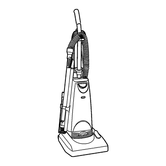
Vacuum Cleaner
MC-UG509-00
Specifications are subject to change without notice for further improvement.
©
2010
PANASONIC
HOME
APPLIANCES
COMPANY,
DIVISION
OF
PANSONIC
CORPORATION OF NORTH AMERICA. All rights
reserved. Unauthorized copying and distribution is a
violation of law.
Advertisement
Table of Contents

Related Manuals for Panasonic MC-UG509-00


Summary of Contents for Panasonic MC-UG509-00
- Page 1 Order Number MAC1008001CE Vacuum Cleaner MC-UG509-00 Specifications are subject to change without notice for further improvement. © 2010 PANASONIC HOME APPLIANCES COMPANY, DIVISION PANSONIC CORPORATION OF NORTH AMERICA. All rights reserved. Unauthorized copying and distribution is a violation of law.
-
Page 2: Table Of Contents
MC-UG509-00 CONTENTS Page Page 1 WIRING DIAGRAM AND DRAWING 3.3. Brush Replacement 1.1. Wiring Diagram 3.4. Belt Replacement 1.2. PICTORIAL DIAGRAM 3.5. Handle Release Assembly 2 EXPLODED VIEW AND PARTS LIST 3.6. Carpet/Bare Floor Assembly 2.1. Body 4 REPLACEMENT INSTRUCTIONS 2.2. -
Page 3: Wiring Diagram And Drawing
MC-UG509-00 1 WIRING DIAGRAM AND DRAWING 1.1. Wiring Diagram... -
Page 4: Pictorial Diagram
MC-UG509-00 1.2. PICTORIAL DIAGRAM NOTE: For general servicing, it is necessary to eliminate pinching of any wire during reassembly. After servicing any electrical component or electrical enclosure, the unit should be reassembled and checked for dielectric breakdown or current leakage. -
Page 5: Exploded View And Parts List
MC-UG509-00 2 EXPLODED VIEW AND PARTS LIST 2.1. Body 2.1.1. Exploded View... - Page 6 MC-UG509-00 2.1.2. Parts List (Body) Ref. No. Part No. Part Name & Description Quantity Remarks AC78KDJGZV07 DUST COVER INCLUDES ITEMS 54 & 55 AC70PJPZV07 WAND HOLDER INCLUDES ITEM 3 AXTN4+16BFY SCREW (WAND HOLDER) SHIPPED 10 PER PACKAGE AMC98E-V010U SWITCH INCLUDES ITEMS 5 15 & 16...
-
Page 7: Nozzle Housing
MC-UG509-00 2.2. Nozzle Housing 2.2.1. Exploded View... - Page 8 MC-UG509-00 2.2.2. Parts List (Nozzle Housing) Ref. No. Part No. Part Name & Description Quantity Remarks AC97ADDWZV07 LOWER BODY UNIT AC01CDDWZV07 WHEEL AC16CNXZ00 ROLLER SHAFT AC27ADDWZ000 LOWER PLATE AXTN4+10BFY SCREW SHIPPED 10 PER PACKAGE AC99QCYBZV06 WHEEL UNIT AC11ADDXZ000 FELT (LOWER)
-
Page 9: Packing Materials
MC-UG509-00 2.3. Packing Materials 2.3.1. Exploded View 2.3.2. Parts List (Packing Materials) Ref. No. Part No. Part Name & Description Quantity Remarks AC61ZDKVZ000 Packing Assembly Includes 1 and items a thru f AC01ZDKXZ000 Operating Instructions... -
Page 10: Replacement Instructions
MC-UG509-00 3 REPLACEMENT INSTRUCTIONS 3.1. Lower Plate Replacement 3.1.1. Removal 1. Before servicing any parts, disconnect vacuum from electrical outlet. 2. Place paper under nozzle whenever lower plate is removed to protect floor. 3. Place handle in upright position and turn vacuum over to expose lower plate. -
Page 11: Belt Replacement
3.4.2. Installation the agitator tube. 1. Loop new belt (Panasonic Type UB8 only) around motor shaft and agitator pulley; see illustration for correct belt routing. 2. Reinstall slide arc into end cap slots, as outlined in the Agitator Assembly Replacement section. -
Page 12: Carpet/Bare Floor Assembly
MC-UG509-00 3. Once the carpet/bare floor pedal assembly is out it can be disassembled for parts replacement as shown in the Exploded View diagram. 3. Remove the three (3) screws that secure the handle release 3.6.2. Installation assembly to the nozzle housing. -
Page 13: Replacement Instructions
MC-UG509-00 4 REPLACEMENT INSTRUCTIONS 4.1. Motor Replacement pinching of any wire during reassembly. After servicing any electrical component or electrical enclosure, the vacuum 4.1.1. Removal cleaner should be reassembly and checked for dielectric breakdown or current leakage. 1. Remove the dust cover. -
Page 14: Power Cord / On-Off Switch Replacement
MC-UG509-00 4.3. Power Cord / On-Off Switch 4.2.2. Installation Replacement 1. Install new bulb socket into motor case. 2. Connect yellow lead wire to fan motor. 4.3.1. Removal 3. Connect white lead wire from bulb socket, black lead wire 1. Remove the dust cover and switch cover to expose the from motor a wire nut. -
Page 15: Nozzle Replacement
MC-UG509-00 3. Ensure that the insulator packing is installed correctly. 4. Once left side has cleared, remove nozzle housing from motor shaft. 4.4.2. Installation 1. Fit the nozzle from the motor shaft side first, and rotate it into place on the dust container.
Need help?
Do you have a question about the MC-UG509-00 and is the answer not in the manual?
Questions and answers