Advertisement
Quick Links
Basys 2™ FPGA Board Reference Manual
Revised April 8, 2016
This manual applies to the Basys 2 rev. C
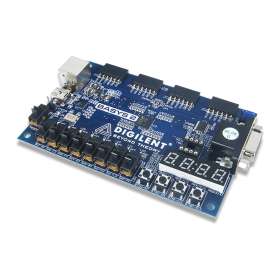
Overview
The Basys 2 board is a circuit design and implementation platform that anyone can use to gain experience building
real digital circuits. Built around a Xilinx Spartan-3E Field Programmable Gate Array and a Atmel AT90USB2 USB
controller, the Basys 2 board provides complete, ready-to-use hardware suitable for hosting circuits ranging from
basic logic devices to complex controllers. A large collection of on-board I/O devices and all required FPGA support
circuits are included, so countless designs can be created without the need for any other components.
Full Speed
USB2 Port
(JTAG and data transfers)
Data
JTAG
20
port
port
Xilinx Spartan3E-100 CP132
32
2
PS/2
VGA Port
I/O Devices
Port
Figure 1. The Basys 2 board block diagram and features.
Four standard expansion ports allow designs to grow beyond the Basys 2 board using breadboards, user-designed
circuit boards, or Pmods (Pmods are inexpensive analog and digital I/O modules that offer A/D & D/A conversion,
motor drivers, sensor inputs, and many other features). Signals on the 6-pin connectors are protected against ESD
damage and short-circuits, ensuring a long operating life in any environment. The Basys 2 board works seamlessly
with all versions of the Xilinx ISE tools, including the free WebPack. It ships with a USB cable that provides power
and a programming interface, so no other power supplies or programming cables are required.
The Basys 2 board can draw power and be programmed via its on-board USB2 port. Digilent's freely available PC-
based Adept software automatically detects the Basys 2 board, provides a programming interface for the FPGA and
Platform Flash ROM, and allows user data transfers (see
DOC#: 502-155
Other product and company names mentioned may be trademarks of their respective owners.
Platform
Settable Clock
Flash
Source
(config ROM)
(25 / 50 / 100 MHz)
8 bit
4
4
4
color
JA
JB
JC
JD
Pmod Connectors
Copyright Digilent, Inc. All rights reserved.
100,000-gate Xilinx Spartan 3E FPGA
Atmel AT90USB2 Full-speed USB2 port
providing board power and programming/data
transfer interface
Xilinx Platform Flash ROM to store FPGA
configurations
8 LEDs, 4-digit 7-segment display, 4 buttons, 8
slide switches
PS/2 port and 8-bit VGA port
4
User-settable clock (25/50/100MHz), plus
nd
socket for 2
clock
Four 6-pin header expansion connectors
ESD and short-circuit protection on all I/O
signals.
www.digilentinc.com
for more information).
1300 Henley Court
Pullman, WA 99163
509.334.6306
www.digilentinc.com
Page 1 of 12
Advertisement

Related Manuals for Digilent Basys 2


Summary of Contents for Digilent Basys 2
- Page 1 This manual applies to the Basys 2 rev. C Overview The Basys 2 board is a circuit design and implementation platform that anyone can use to gain experience building real digital circuits. Built around a Xilinx Spartan-3E Field Programmable Gate Array and a Atmel AT90USB2 USB controller, the Basys 2 board provides complete, ready-to-use hardware suitable for hosting circuits ranging from basic logic devices to complex controllers.
-
Page 2: Board Power
The Basys 2 board uses a four layer PCB, with the inner layers dedicated to VCC and GND planes. The FPGA and the other ICs on the board have large complements of ceramic bypass capacitors placed as close as possible to each VCC pin, resulting in a very clean, low-noise power supply. - Page 3 Basys2™ FPGA Board Reference Manual To program the Basys 2 board, set the mode jumper Atmel to PC and attach the USB cable to the board. Start the Adept software, and wait for the FPGA and the AT90USB2 Mode Jumper Platform Flash ROM to be recognized.
-
Page 4: Seven-Segment Display
If the update or “refresh” rate is slowed to a given point (around 45 hertz), then most people will begin to see the display flicker. Copyright Digilent, Inc. All rights reserved. Page 4 of 12 Other product and company names mentioned may be trademarks of their respective owners. - Page 5 A PS/2 interface circuit can be implemented in the FPGA to create a keyboard or mouse interface. Copyright Digilent, Inc. All rights reserved. Page 5 of 12 Other product and company names mentioned may be trademarks of their respective owners.
- Page 6 Pin6: Clock DATA Pin8: Clock 6-pin mini-DIN (bottom up) Figure 9. PS/2 connector and Basys 2 PS/2 circuit. Keyboard Tck Tck The keyboard uses open-collector drivers so the keyboard or an Edge 0 Edge 10 attached host device can drive the two-wire bus (if the host ‘0’...
- Page 7 Start bit Stop bit Start bit Start bit Idle state Idle state Figure 12. Mouse data format. Copyright Digilent, Inc. All rights reserved. Page 7 of 12 Other product and company names mentioned may be trademarks of their respective owners.
-
Page 8: Vga Port
VGA Port The Basys 2 board uses 10 FPGA signals to create a VGA port with 8-bit color and the two standard sync signals (HS – Horizontal Sync, and VS – Vertical Sync). The color signals use resistor-divider circuits that work in conjunction with the 75-ohm termination resistance of the VGA display to create eight signal levels on the red and green VGA signals, and four on blue (the human eye is less sensitive to blue levels). - Page 9 Horizontal display time Video data typically comes from a video time refresh memory, with one or more bytes time assigned to each pixel location (the Basys 2 Horizontal sync signal uses three bits per pixel). The controller must "front porch" "back porch"...
- Page 10 Expansion Connectors (6-pin Headers) The Basys 2 board provides four 6-pin peripheral module connectors. Each connector provides Vdd, GND, and four unique FPGA signals. Several 6-pin module boards that can attach to this connector are available from Digilent, including A/D converters, speaker amplifiers, microphones, H-bridge amplifiers, etc.
-
Page 11: Built-In Self Test
Basys2™ FPGA Board Reference Manual FPGA Pin Definitions The table below shows all pin definitions for the Spartan-3E on the Basys 2 board. Pins in grey boxes are not available to the user. FPGA pin definition table color key Grey... - Page 12 If the self test is not resident in the Platform Flash ROM, it can be programmed into the FPGA or reloaded into the ROM using the Adept programming software. Copyright Digilent, Inc. All rights reserved. Page 12 of 12 Other product and company names mentioned may be trademarks of their respective owners.
Need help?
Do you have a question about the Basys 2 and is the answer not in the manual?
Questions and answers