Advertisement
SPECIFICATIONS
Power source
Input power
Water lift
Cord length
Radio of operation
Net weight
Dimensions (LxWxH) mm
Attachments:
Floor nozzle
Metallic tube
Dusting brush
Crevice nozzle
Upholstery nozzle
Specifications are subject to change without notice for further improvement.
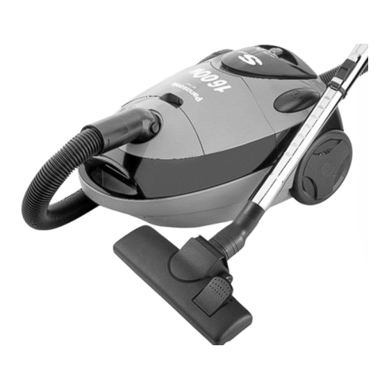
MODELS MC-E881, MC-E883, MC-E885
MC-E881
MC-E883
AC230V
AC230V
AC230-240V
AC230-240V
50Hz
50Hz
450-1500W
450-1600W
30 kPa
31 kPa
5.5 m
5.5 m
8.2 m
8.2 m
7.0 kg
7.2 kg
460x313x243
460x313x243
•
•
Extension tube
Telescopic tube
•
•
•
•
•
•
MC-E885
AC230V
Depending on version
AC230-240V
50Hz
450-1600W
31 kPa
5.5 m
8.2 m
7.3 kg
460x313x243
•
Telescopic tube
•
•
•
Matsushita Electric España, S.A.
DIVISION DE ASPIRADORAS
Zona Industrial del Polígono de CELRÀ
17460 CELRÀ (Girona) SPAIN
Ref.: Z32P6000
Vacuum Cleaner
Advertisement
Table of Contents

Related Manuals for Panasonic MC-E881


Summary of Contents for Panasonic MC-E881
-
Page 1: Specifications
Ref.: Z32P6000 Vacuum Cleaner MODELS MC-E881, MC-E883, MC-E885 SPECIFICATIONS MC-E881 MC-E883 MC-E885 Power source AC230V AC230V AC230V Depending on version AC230-240V AC230-240V AC230-240V 50Hz 50Hz 50Hz Input power 450-1500W 450-1600W 450-1600W Water lift 30 kPa 31 kPa 31 kPa Cord length 5.5 m... -
Page 2: Table Of Contents
TABLE OF CONTENTS PAGE SPECIFICATIONS ................SCHEMATIC DIAGRAM . -
Page 3: Schematic Diagram
SCHEMATIC DIAGRAM MC-E881 / MC-E883 / MC-E885 VR12 VR22 VR21 VR11 TRIAC Yellow DIAC C3 + THERMAL CUT-OUT Black Black THS1 POWER SUPPLY ON/OFF SWITCH White PICTORIALWIRING DIAGRAM MC-E881 / MC-E883 / MC-E885 White MOTOR White POTENTIOMETER Blue Grey White... -
Page 4: Exploded View
EXPLODED VIEW... - Page 5 EXPLODED VIEW...
- Page 6 EXPLODED VIEW...
- Page 7 EXPLODED VIEW...
-
Page 8: Spare Parts List
SPARE PARTS LIST Applied for REF. No. DESCRIPTION PART No. Pcs/Set MC-E881 MC-E883 MC-E885 REMARKS all countries ( ) HOSE UNIT AMC8A92P1034 • • • HOSE AMC8A0131034 • • • CURVED TUBE ASS’Y AMC8A94P1034 • • • HOSE HOLDER AMC8A1125034 •... - Page 9 SPARE PARTS LIST Applied for REF. No. DESCRIPTION PART No. Pcs/Set REMARKS MC-E881 MC-E883 MC-E885 all countries ( ) FLOOR NOZZLE HOOK AMC8C25L1034 • • • TAPPING SCREW XTN4+18B • • • HANDLE COVER AMC8T23P1034 • • • TAPPING SCREW XTN4+18B •...
- Page 10 SPARE PARTS LIST Applied for REF. No. DESCRIPTION PART No. Pcs/Set MC-E881 MC-E883 REMARKS MC-E885 all countries ( ) SWIVEL BASE AMC8T40J1034 • • • DUST BAG SEAL AMC8F05P1000 • • • SWIVEL BASE COVER AMC8T41J1134 • • • FRONT COVER (White colour) AMC8T11P1020 •...
-
Page 11: Replacement Of Main Parts
REPLACEMENT OF MAIN PARTS IMPORTANT: Before replacing any part always Screw DISCONNECT THE CLEANER FROM THE ELECTRICITY SUPPLY. • MOTOR / CARBON BRUSHES (1) Motor Pedal cover 1. Remove 1 screw from the pedal cover and take it out. (Fig. 1) Fig. - Page 12 REMPLACEMENT OF MAIN PARTS 4. Remove the lead wires (provided with quick-connect Quick-connect terminals terminal) from the contact springs tab-terminals and take out cord reel ass’y. (Fig. 3) Cord reel ass’y Fig. 3 5. Take out motor ass’y, and disconnect from the power control circuit tabs yellow and white lead wires (provided with Tab-terminals Motor cover...
- Page 13 REPLACEMENT OF MAIN PARTS (2) Carbon brushes Cut metal end NOTE: Replace both carbon brushes at the same time. 1. Take out motor ass’y and remove motor cover as explai- ned in paragraph (1) Motor, points 1-6. 2. Bend the metal end of the carbon brush holder and take out the carbon brush.
- Page 14 REPLACEMENT OF MAIN PARTS • POWER CONTROL CIRCUIT / SLIDING Power control circuit POTENTIOMETER (1) Power control circuit 1. Remove upper body as explained in paragraph (1) Motor, points 1-4. 2. Take out body cover and release power control circuit from its fastening points.
- Page 15 REPLACEMENT OF MAIN PARTS • CORD REEL UNIT / POWER CORD SUPPLY (1) Cord reel unit Cord reel Cord reel support assembly 1. Remove upper body and cord reel ass’y as explained in paragraph (1) Motor, points 1-4. 2. Unwind the power cord to release the cord reel spring. Then remove the screw from the cord reel support.
- Page 16 REPLACEMENT OF MAIN PARTS • BRAKE LEVER UNIT Cord reel 1. Remove upper body as explained in paragraph (1) Motor, pedal points 1-3. 2. Take out cord reel pedal prising on its shaft with a flat-head Spring screwdriver. (Fig. 18) Pedal shaft Fig.
-
Page 17: Trouble Shooting Guide
TROUBLE SHOOTING GUIDE CONDITION CHECKPOINT METHOD OF INSPECTION CAUSE / REMEDY Motor fails to rotate. Power cord Check power cord continuity between If there is no continuity, (no noise is heard connection. plug pins and base contact. replace the power cord. at all). -
Page 18: Packing Instructions
PACKING INSTRUCTIONS...
Need help?
Do you have a question about the MC-E881 and is the answer not in the manual?
Questions and answers