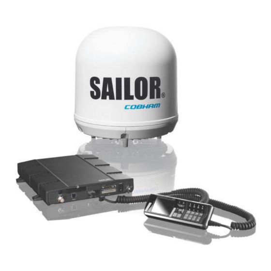
COBHAM SAILOR 150 User Manual
Fleetbroadband
Hide thumbs
Also See for SAILOR 150:
- Installation manual (88 pages) ,
- Quick manual (2 pages) ,
- Quick reference (2 pages)
Table of Contents
Advertisement
Quick Links
Advertisement
Table of Contents
Troubleshooting

Related Manuals for COBHAM SAILOR 150


Summary of Contents for COBHAM SAILOR 150
- Page 1 SAILOR 150 FleetBroadband User manual...
- Page 2 Thrane & Thrane A/S is not responsible for the content or accuracy of any translations or reproductions, in whole or in part, of this manual from any other source. Thrane & Thrane A/S is trading as Cobham SATCOM. Copyright © 2014 Thrane & Thrane A/S. All rights reserved.
- Page 3 During transmission, make sure that nobody gets closer than the recommended minimum safety distance. On the SAILOR 150 FleetBroadband, the minimum safety distance to the antenna panel on the focal line is 0.6 m, based on a radiation level of 10 W/m .
- Page 4 Compass Safe Distance: SAILOR 150 FleetBroadband Terminal: min. 0.3 m. SAILOR 150 FleetBroadband Antenna: min. 1.2 m Service User access to the interior of the system units is prohibited. Only a technician authorized by Thrane & Thrane A/S may perform service - failure to comply with this rule will void the warranty.
-
Page 5: About The Manual
About the manual Intended readers This manual is a user manual for the SAILOR 150 FleetBroadband System. The readers of the manual include anyone who is using or intends to use this system. No specific skills are required to operate the SAILOR 150 FleetBroadband System. However, it is important that you observe all safety requirements listed in the beginning of this manual, and operate the system according to the guidelines in this manual. -
Page 6: Related Documents
Related documents The below list shows the documents related to this manual and to the SAILOR 150 FleetBroadband System. Document Title and description number SAILOR 150 FleetBroadband, Installation Manual 98-129218 Explains how to install the SAILOR 150 FleetBroadband Terminal and the SAILOR 150 FleetBroadband Antenna. -
Page 7: Table Of Contents
Table of Contents Safety summary ..........................iii About the manual ...........................v Chapter 1 Introduction Welcome ............................. 1 Features and interfaces ......................2 Main units ............................3 The Inmarsat BGAN system ..................... 6 Access to services and interfaces ................10 Chapter 2 Getting started Before you start .........................12 Starting up the terminal... - Page 8 Table of Contents Using the Dashboard ......................52 Using the phone book ......................55 Using the Call log ........................58 Handling SMS messages ....................60 Setting up the interfaces ....................65 Uploading software ........................96 Selecting the preferred BGAN satellite ...............99 Selecting the language .....................100 Administration .........................101 Help desk and diagnostic report ................119...
-
Page 9: Chapter 1 Introduction
Chapter 1 Introduction Welcome Congratulations on the purchase of your SAILOR 150 FleetBroadband System! SAILOR 150 FleetBroadband is a maritime broadband system, providing simultaneous high- speed data and voice communication via satellite through the BGAN (Broadband Global Area Network). Applications include: •... -
Page 10: Features And Interfaces
• Access to services and interfaces Features and interfaces The SAILOR 150 FleetBroadband System offers the following features and interfaces: Simultaneous voice and data communication over BGAN Full duplex, single or multi-user, up to: 150 kbps Standard Voice (4 kbps) or 3.1 kHz Audio ... -
Page 11: Main Units
TT-3670A IP Handset & Cradle, wired SAILOR 150 FleetBroadband Antenna The SAILOR 150 FleetBroadband System uses the TT-3050C antenna, which is a small size maritime 2-axis stabilized BGAN antenna. For information on how to install the antenna, refer to the installation manual. - Page 12 SAILOR 150 FleetBroadband Terminal Overview The SAILOR 150 FleetBroadband Terminal is the controlling unit in the SAILOR 150 FleetBroadband System. It contains all user interfaces and a Power LED indicator and stores configuration data. Tools for setup and daily use The Thrane IP Handset can be used for displaying status, accessing a subset of controls and views, starting a streaming session and entering the PIN code for the terminal.
- Page 13 The Thrane IP Handset communicates using Internet Protocols (IP). The handset is not strictly dedicated to the SAILOR 150 FleetBroadband System, but can also be used in a public network as a standard IP telephone. The Thrane IP Handset is powered directly from the LAN interface using Power over Ethernet (PoE).
-
Page 14: The Inmarsat Bgan System
Chapter 1: Introduction The Inmarsat BGAN system What is BGAN? The Broadband Global Area Network (BGAN) is a mobile satellite service that offers high-speed data and voice telephony. BGAN enables users to access e-mail, corporate networks and the Internet, transfer files and make telephone calls. The Inmarsat FleetBroadband service FleetBroadband is a maritime communications service offered in the BGAN system. -
Page 15: Supported Services
Overview of the BGAN FleetBroadband system A complete BGAN FleetBroadband system includes the SAILOR 150 FleetBroadband Terminal with connected peripherals, a SAILOR 150 FleetBroadband Antenna, the BGAN satellite, and the Satellite Access Station (SAS). The satellites are the connection between your terminal and the SAS, which is the gateway to the worldwide networks (Internet, telephone network, cellular network, etc.). -
Page 16: Packet Data Service
Chapter 1: Introduction Packet data service The packet data service available for the SAILOR 150 FleetBroadband offers a Standard IP (background) connection where several users can share the data connection simultaneously. This type of connection is ideal for e-mail, file transfer, and Internet and intranet access. The user pays for the amount of data sent and received. -
Page 17: Supplementary Services
Chapter 1: Introduction Supplementary services The BGAN system also provides the following supplementary services: • Call hold • Call waiting • Call forwarding • Voice mail • Call barring Service limitations SIM lock The supplier may have locked the SIM card to a specific provider. For further information, contact your supplier. -
Page 18: Access To Services And Interfaces
Chapter 1: Introduction Access to services and interfaces The following table shows which equipment and interfaces you can use to access the services listed in the left column. Interface on the terminal Service Phone/Fax LAN (PoE) Analog telephone IP handset 3.1 kHz Audio G3 Fax machine Standard... -
Page 19: Chapter 2 Getting Started
Registering with the BGAN network • Making the first call • Standard connection to the Internet (default) For information on how to install the system, insert SIM card and connect cables, refer to the installation manual for the SAILOR 150 FleetBroadband System. 98-129217-D... -
Page 20: Before You Start
For further information on installation, refer to the installation manual for the SAILOR 150 FleetBroadband System. Connector panel The drawing below shows the connector panel of the SAILOR 150 FleetBroadband Terminal. Power DC input Reset button Slot for SIM card... -
Page 21: Using The Power Switch
15 mA when the ignition is off. For information on how to connect to the Ignition pins in the I/O connector, refer to the installation manual for the SAILOR 150 FleetBroadband System. You must set up the ignition function in the web interface. For further information, see Configuring the I/O interface on page 93. - Page 22 Chapter 2: Getting started Power up completed When the terminal is switched on, the Power indicator in the terminal lights green. You can now access the terminal settings, but the terminal is not ready for making calls or running data sessions until the system is registered on the BGAN network. You may have to enter a SIM PIN before the system can register.
-
Page 23: Connecting The Thrane Ip Handset
Chapter 2: Getting started Connecting the Thrane IP handset Power supply (PoE) The Thrane IP Handset is powered from the LAN interface, using Power over Ethernet. The total output power from the two interfaces is 32 W. Both interfaces can support devices of power class 1, 2 and 3 (4, 7 and 15.4 Watt), as long as the total power consumption does not exceed 32 W. -
Page 24: Connecting A Computer
Chapter 2: Getting started Connecting a computer Before connecting to the LAN interface For the LAN interface to work without any further setup, the connected computer must be set up to obtain an IP address and a DNS server address automatically. To check this on your computer (Windows XP), do as follows: 1. - Page 25 Chapter 2: Getting started Using an Administrator user name and password you can change the PIN and enable Note or disable the use of a PIN. For further information, see Setting up the use of a SIM PIN in the terminal on page 107. For information on how to connect the Thrane IP Handset or computer you are going to use, see Connecting a computer to the LAN interface on page 16 or Connecting the Thrane IP handset on page 15.
- Page 26 Chapter 2: Getting started enter the SIM PIN, before you are asked to enter the PUK (Pin Unblocking Key). The PUK is supplied with the SIM card for your terminal. Enter the PUK followed by a new PIN of your own choice. The PIN must be from 4 to 8 digits long.
-
Page 27: Registering With The Bgan Network
Airtime Provider for a new SIM card. Registering with the BGAN network When the SIM PIN is accepted by the terminal, the SAILOR 150 FleetBroadband System automatically starts the registration procedure on the BGAN network. You can monitor the registration procedure in two ways. -
Page 28: Making The First Call
To make a call from a phone connected to the terminal, dial 00 <country code> <phone number> followed by # or off-hook key. Example:To call Cobham SATCOM in Denmark (+45 39558800) from an analogue phone, dial 00 45 39558800 #... -
Page 29: Standard Connection To The Internet (Default)
Chapter 2: Getting started Standard connection to the Internet (default) This section only describes a Standard Internet connection with default settings on Note the terminal. For information on other scenarios, see Setting up the LAN network on page 70. By default, the terminal does not automatically connect to the Internet when you connect your computer or other equipment to the LAN interface. - Page 30 Chapter 2: Getting started Activating the connection using the Thrane IP Handset To activate the connection using the Thrane IP Handset, do as follows: 1. Connect the Thrane IP Handset to one of the LAN ports (preferably port 1). The handset starts up automatically.
-
Page 31: Chapter 3 Operating The System
Chapter 3 Operating the system This chapter describes how to use the SAILOR 150 FleetBroadband System. It has the following sections: • General • Using a phone or fax machine • Multi-voice (optional) • Voice Distress (optional) • Using a computer •... - Page 32 Chapter 3: Operating the system • Viewing active events • Viewing GPS status • Contacts: • Inclusion of the terminal phone book (not editable) in the Thrane IP Handset Contacts • SIP (Session Initiation Protocol): • Selecting/viewing/configuring the SIP profile used for communication with the BGAN terminal •...
- Page 33 Chapter 3: Operating the system • change the SIM PIN for the terminal • set up user rights (requires administrator password) • set up remote management and activation • set up restricted dialling • set up Multi-voice • set up Voice Distress •...
-
Page 34: Using A Phone Or Fax Machine
Phone/Fax 2 x LAN w. PoE For information on how to connect to the interfaces, see the installation manual for the SAILOR 150 FleetBroadband System. Selecting the call type Definition The phone connection can use one of the following call types: Standard Voice, which is a low-tariff voice connection compressed to 4.0 kbps... - Page 35 • dial 2* before the number. Example:To make a call to Cobham SATCOM in Denmark (+45 39558800), forcing the connection to use Standard Voice, dial 1* 0045 39558800 followed by # if calling from an analogue phone, or off-hook key if calling from an IP handset.
- Page 36 • 00 <country code> <phone number> followed by # or off-hook key. Example: To call Cobham SATCOM in Denmark (+45 39558800) from an analogue phone, dial 00 45 39558800 # Call from phone book or call log (only Thrane IP Handset).
- Page 37 Chapter 3: Operating the system Receiving a call By default, all devices connected to the Phone interface or the LAN (PoE) interface will ring when one of the mobile numbers is called. Note, however, that this depends on the call type settings.
- Page 38 Chapter 3: Operating the system To see that a new SMS has arrived you open the web interface. For further details see Receiving a message on page 62. Making local phone calls You can make local calls between phones connected to the terminal. Local phone numbers always start with 0.
- Page 39 Chapter 3: Operating the system *31# before the phone number will show the caller’s phone number to the recipient where • it would otherwise be hidden, e.g. because the number is an ex-directory number. • For analogue 2-wire telephones, use the R key during a call to get access to a supplementary services function.
- Page 40 Chapter 3: Operating the system Holding a call During a call, you may place the initial call on hold while another call is made. Different types of phone have different methods/keys for the functions listed below. Note If you have another type of phone than the ones listed below, refer to the documentation for your phone/handset.
- Page 41 Chapter 3: Operating the system Transferring a call When you receive a call, you can transfer this call to another phone connected to the terminal. Different types of phone have different methods/keys for the functions listed below. Note If you have another type of phone than the ones listed below, refer to the documentation for your phone/handset.
- Page 42 To send a fax from a fax machine connected to the terminal, dial 00 <country code> <phone number> # Example:To send a fax to Cobham SATCOM in Denmark (+45 39558888), dial 00 45 39558888 # Sending a fax message to the terminal To send a fax message to the terminal, dial + <Mobile number>...
-
Page 43: Multi-Voice (Optional)
Chapter 3: Operating the system Multi-voice (optional) You can add Multi-voice to your airtime subscription, enabling you to have up to 4 simultaneous calls. You can subscribe to Multi-voice with or without additional numbers. You must have Multi-voice in your airtime subscription, Note Thrane IP Handset software version minimum 1.13 and terminal software version minimum 1.15, in order to support... - Page 44 Chapter 3: Operating the system Call type groups The handsets are called using one of the mobile numbers for either Standard Voice or 3.1 kHz audio. All handsets in a group will ring when the belonging number is called. For information on how to associate a handset with a group, see •...
- Page 45 Chapter 3: Operating the system Example of directly assigned handsets: Note that you can also assign the call type numbers directly (in the example above, the Standard Voice number is assigned to IP handset number 0501). If you do so, be aware that only the assigned handset can receive a call to this number.
- Page 46 Chapter 3: Operating the system Additional numbers for Multi-voice You must have Multi-voice with additional numbers in your Note airtime subscription to be able to use this feature. In addition to the phone numbers for incoming Standard Voice and 3.1 kHz Audio, your subscription may include extra phone numbers that can be assigned to specific handsets.
-
Page 47: Voice Distress (Optional)
Distress must be at least version 1.12, in order to support the Voice Distress function. The Voice Distress system includes a FleetBroadband system, a SAILOR 3771 Alarm Panel and a Thrane IP Handset. SAILOR 150/250/500 System S150 / Optional S250 /... -
Page 48: Using A Computer
The terminal has two LAN connectors for connecting computers, Thrane IP Handsets or other LAN equipment. For information on how to connect to the interfaces, see the installation manual for the SAILOR 150 FleetBroadband System. Router function The terminal has a router function which routes traffic between the local network connected to the terminal and network connections or PDP contexts on the BGAN network. -
Page 49: Connecting To The Internet
Chapter 3: Operating the system Connecting to the Internet Default setup By default, any IP device that is connected to the terminal belongs to the Default network user group. It uses a Standard shared IP connection, which you must manually activate from the web interface. - Page 50 Chapter 3: Operating the system Accessing the terminal from a remote location Preparing the terminal for remote management There are three steps you must go through before you can access the terminal from a remote location: 1. Set up the terminal for control from a remote location as described in Remote management on page 111.
- Page 51 Chapter 3: Operating the system Accessing the terminal using web interface After preparing the terminal as described in the previous sections, do as follows to access it: 1. Make sure your remote computer has access to the Internet. 2. On the remote computer, open your web browser. 3.
- Page 52 Chapter 3: Operating the system Using PPPoE (Point-to-Point Protocol over Ethernet) Overview You can establish a PPPoE connection to the BGAN network using the SAILOR FleetBroadband system. Use PPPoE if you want to control your connection independently of the web interface and the Thrane IP Handset.
-
Page 53: Using The Thrane Ip Handset
XBB:AT+CGDCONT=1,ip,”bgan.inmarsat.com” Using the Thrane IP Handset You can use the Thrane IP Handset as a user interface for the SAILOR 150 FleetBroadband System as well as for making calls. The Thrane IP Handset has a dedicated menu for the SAILOR 150 FleetBroadband System. You find a list of the menu items available in The Thrane IP Handset on page 23. -
Page 54: Chapter 4 Using The Web Interface
Chapter 4 Using the web interface This chapter describes how to use the web interface to operate, set up and configure your SAILOR 150 FleetBroadband System. It has the following sections: • Introduction • Entering the SIM PIN in the web interface •... - Page 55 Chapter 4: Using the web interface To disable the use of a Proxy server completely, do as follows: The following description is for Microsoft Internet Note Explorer. If you are using a different browser, the procedure may be different. 1. In Microsoft Internet Explorer, select Tools > Internet Options > Connections > LAN Settings.
- Page 56 Chapter 4: Using the web interface Accessing and navigating the web interface Accessing the web interface To access the web interface, do as follows: 1. Connect your computer to the terminal. 2. Start up the terminal. For details, see Getting started on page 11. 3.
- Page 57 Chapter 4: Using the web interface Overview of the web interface When the web interface opens, the title bar of your browser shows the name of the product. The web interface consists of the following sections. Icon bar Contents section Signal strength Navigation...
- Page 58 Chapter 4: Using the web interface Icons in the icon bar The following icons may appear in the icon bar in the web interface: Icon Explanation A new SMS message, or information of Voice mail, has arrived. Click the icon to see new messages or information of Voice mail.
-
Page 59: Entering The Sim Pin In The Web Interface
Chapter 4: Using the web interface Entering the SIM PIN in the web interface Do you need a SIM PIN? You may not have to enter a SIM PIN to access the terminal. This depends on Note whether or not the use of a SIM PIN is enabled on your SIM card. The administrator can enable and disable the use of a SIM PIN. -
Page 60: Using The Dashboard
Chapter 4: Using the web interface Using the Dashboard Overview The Dashboard is used for control and inspection of ongoing communication and for viewing properties and status of the terminal and antenna. For information on how to start or stop your data sessions from the Dashboard, see Connecting to the Internet on page 41. - Page 61 The PROPERTIES section of the DASHBOARD shows the following information: Airtime provider. The name of your Airtime Provider. • GPS position. The GPS position of your SAILOR 150 FleetBroadband System. • In some cases, the BGAN network does not allow the position to be displayed to Note the user.
- Page 62 Chapter 4: Using the web interface Viewing information on calls and data sessions The following sections in the Dashboard show information on calls and data sessions. The counters for calls and data sessions are only intended as a guide and cannot be Note used for direct comparison with your airtime bill.
-
Page 63: Using The Phone Book
Chapter 4: Using the web interface Using the phone book General usage Overview In the phone book you can: • Look up phone numbers. • Look up short-dial numbers for easy dialling from a handset. • Modify or delete existing names and phone numbers, or add new names and phone numbers. - Page 64 Chapter 4: Using the web interface The phone book shows all entries with entry number, name and phone number. Empty place holders are also included. To sort the phone book, click the title of the column you wish to sort by. For example, to sort by the names in the phone book alphabetically, click on Name in the top row of the phone book.
- Page 65 Chapter 4: Using the web interface Viewing and editing the mobile numbers The mobile numbers are the phone numbers to use when making a call to the terminal. To view the mobile numbers To view the mobile numbers of the terminal, select PHONE BOOK > Mobile numbers from the left navigation pane.
-
Page 66: Using The Call Log
Chapter 4: Using the web interface Using the Call log If power to the system is interrupted, the information on the currently ongoing calls Note (connection time) and data sessions (transferred data) cannot be saved. This could mean that the airtime and bandwidth usage registered in the Call log will be inaccurate and there is a risk of being charged for more airtime than registered in the web interface. - Page 67 Date and time is the international UTC time, received from the satellite. For information on the available types of service, see The BGAN services supported by SAILOR 150 FleetBroadband on page 7. The estimated charge is based on your entries under ADMINISTRATION > Call Note charges.
-
Page 68: Handling Sms Messages
Chapter 4: Using the web interface Handling SMS messages Sending an SMS message If the terminal is not online when you attempt to send a message, the message is Important moved to the Outbox instead of the Sent folder. Messages in the Outbox are not automatically sent when the terminal goes online. - Page 69 Chapter 4: Using the web interface If you click Yes, the Status column in the Sent folder will show the status of your message when it has been sent. You can set up delivery notification generally for all SMS messages. This setting is used by default when you send a message.
- Page 70 Chapter 4: Using the web interface Sending an SMS message to the terminal You can send an SMS message to the terminal e.g. from a mobile phone, using one of the mobile numbers for the terminal. Dial + <Mobile number> The first part of the mobile number is always 870, which is the “country code”...
- Page 71 Chapter 4: Using the web interface Options for SMS messages in the Inbox The messages in the Inbox are the incoming messages that have been read and moved from the list of new messages (refer to the previous section). From the Inbox, you have the following options: Click Reply to reply to a message.
- Page 72 Chapter 4: Using the web interface Viewing or changing SMS service centre number The SMS service centre number identifies the SMS service centre used when sending and receiving SMS messages. The SMS service centre number is stored on the SIM card. •...
-
Page 73: Setting Up The Interfaces
Chapter 4: Using the web interface Setting up the interfaces The SETTINGS page (Antenna properties) The SETTINGS page shows properties of the connected antenna. To access the SETTINGS page, select SETTINGS from the left navigation pane. If the HPA module in the antenna has been exchanged, the Antenna serial number Note field shows “0”. - Page 74 Chapter 4: Using the web interface Configuring the LAN interface Overview The SAILOR 150 FleetBroadband Terminal has 2 LAN connectors with PoE (Power over Ethernet). Some of the LAN parameters are set up in the network management pages, which require administrator password.
- Page 75 Chapter 4: Using the web interface To change the local IP addresses, do as follows: 1. From the left navigation pane, select SETTINGS > LAN. 2. At DHCP status, select Enabled (recommended for most purposes), or Disabled. • If you select Enabled, the terminal assigns dynamic IP addresses to devices connected to the terminal.
-
Page 76: Port Forwarding
Chapter 4: Using the web interface Port forwarding Port forwarding enables you to set up a server connected to the terminal while the terminal is in Router mode. Without port forwarding it would not be possible to contact the server from the Internet. - Page 77 Chapter 4: Using the web interface 6. Repeat step 3. to step 5. to set up port forwarding to additional servers. 7. In the Active column, select which ports should have port forwarding activated. 8. Click Apply. You can now access the mail server from the Internet, using the public IP address of the terminal.
- Page 78 Chapter 4: Using the web interface Setting up the LAN network For most purposes, the default setup is sufficient. Note When you access the LAN network settings you are prompted for the Administrator user name and password. Network user groups Two network user groups are available to the users of the terminal: The Default group: By default, all users belong to the Default network user group, which •...
- Page 79 Chapter 4: Using the web interface Setting up the Default network user group The Default network user group provides a shared Standard connection to the Internet using the built-in router functionality of the terminal. If you want to apply other settings to the Default network user group, do as follows: 1.
- Page 80 Chapter 4: Using the web interface one or more computers are connected using the LAN interface, and the terminal should act as a router. • No Internet access means no connection to the Internet is allowed. Use this setting e.g. if you are going to use Group 0 to establish a Bridge mode connection. 5.
- Page 81 Chapter 4: Using the web interface Setting up a Bridge mode connection To set up a Bridge mode connection, do as follows: 1. Select SETTINGS > LAN > Network user groups. 2. When you are prompted, enter the administrator user name and password. The default user name is admin and the default password is 1234.
- Page 82 Chapter 4: Using the web interface 4. At Status, select Enabled. 5. Select Dynamic IP address. This is the IP address used externally on the satellite network. Refer to the next step for Static IP. 6. If you want to use a static IP address, you must have it included in your airtime subscription and use that address as follows: •...
- Page 83 Chapter 4: Using the web interface 12. Follow the instructions in the warning and set the Default group to No Internet access, if you are going to use the Bridge mode connection. For details on how to set up the Default group, see Setting up the Default network user group on page 71.
- Page 84 Chapter 4: Using the web interface 15. Select or type in the parameters you want to associate with your Group 0. MAC address: If you want only a specific device (MAC address) to belong to Group 0, you can do one of the following: •...
-
Page 85: Header Compression
Chapter 4: Using the web interface Locking an IP address to a MAC address You can only lock an IP address to a MAC address if DHCP is enabled (see Setting up Note the local LAN IP addresses on page 66) and the Internet connection is not a Bridge mode connection. - Page 86 On the equipment connected to the SAILOR 150 FleetBroadband Terminal you must enter a few settings for your PPPoE connection. For example you need to set up which service to use and possibly a user name and password.
- Page 87 Chapter 4: Using the web interface Setting up static routing When you have an external gateway connected to your terminal, the terminal is not automatically able to “see” the network on the other side of the gateway. However, you can set up your terminal to communicate with a device on the other side of a gateway, by using Static routing.
- Page 88 Chapter 4: Using the web interface Configuring the Phone/Fax interface To configure the Phone/Fax interface do as follows: 1. Select SETTINGS > Phone/Fax from the left navigation pane. 2. If you have additional numbers from your airtime provider and you want to assign them to the Phone/Fax port, use the Assigned number drop down list to select the number you want to use.
- Page 89 Chapter 4: Using the web interface Setting the common interface settings Overview The settings under COMMON are common for all interfaces. In order to use the common Access Point Name for an Note interface, you must select Common for the APN setting when setting up the network user group.
- Page 90 Chapter 4: Using the web interface 2. Select the APN. You have the following options: • SIM default. The APN is taken from the SIM card. This is the recommended option, unless you have special requirements. • Network assigned. The APN is assigned from the network. •...
-
Page 91: Call Forwarding
Chapter 4: Using the web interface Call forwarding You can set up the terminal to automatically forward incoming calls to another phone number. This information is saved in the BGAN network so it is available when the call cannot be put through and must be forwarded. -
Page 92: Call Barring
Chapter 4: Using the web interface Call barring Do as follows to bar incoming and/or outgoing calls to and from the terminal: 1. Select SETTINGS > Common > Call barring from the left navigation pane. 2. Click OK next to Read current settings, to make sure the page is updated. 3. -
Page 93: Call Waiting
Chapter 4: Using the web interface Call waiting You can set up whether or not you want to receive notification of waiting calls while you are making a call or transmitting data. Do as follows: 1. Select SETTINGS > Common > Call waiting from the left navigation pane. 2. - Page 94 Chapter 4: Using the web interface Closed user group Your subscription may include one or more closed user groups. A closed user group is a group of users permitted to make calls to each other but not to users outside the group. To define the settings for these user groups, do as follows: 1.
- Page 95 Chapter 4: Using the web interface Managing IP handsets Overview The terminal has 2 LAN (PoE) connectors for connection of IP handsets or other IP equipment. You may connect your IP handsets directly to the LAN interfaces or use a PoE switch to connect more handsets.
- Page 96 Chapter 4: Using the web interface Connecting and configuring IP handsets A Thrane IP Handset that is connected to the LAN interface on the terminal is by Note default automatically registered in the terminal and assigned the first available local number and a password which is the same number.
- Page 97 Chapter 4: Using the web interface With the web interface of the Thrane IP Handset you can access the internal settings of the Thrane IP Handset. For further information, refer to the user manual for the Thrane IP Handset. The handset remains in the list after disconnecting. When the handset is connected again, it is automatically recognized and ready for use.
- Page 98 Chapter 4: Using the web interface • For Incoming calls, you can select Standard or 3.1 kHz Audio or both. If you select both, the handset will react (ring) on any incoming call. If, for example, you select Standard, the handset will only react on calls made to the Standard phone number.
- Page 99 Chapter 4: Using the web interface Configuring the discrete I/O interface I/O pins and their functions The I/O interface on the terminal has 5 configurable I/O pins. You can set up the function of each pin in the web interface. The default functions of the I/O pins are as follows: Pin 1: Ringer output.
- Page 100 Chapter 4: Using the web interface BGAN network. No transmission is allowed until the pin is deactivated. You can configure pin 4 to Active low or Active high. • Active low (default): Connect pin 4 to ground (< 1.2 V DC) when it should be activated. •...
- Page 101 Chapter 4: Using the web interface Configuring the I/O interface To configure the I/O pins, do as follows: 1. Select SETTINGS > Discrete I/O. 2. For each pin you want to use, select Enabled. 3. For each pin, select the function of the pin. Refer to the previous section, I/O pins and their functions on page 91.
- Page 102 Chapter 4: Using the web interface Setting up Tracking The SAILOR FleetBroadband system can be used for tracking purposes. You can set up the terminal to report to a server at certain time intervals or after moving a specified distance. You cannot use the external data connection for anything else while you are using the Note tracking function.
- Page 103 Chapter 4: Using the web interface • Server port. Port number on the server. Default number is 7474. • Client port. Port number on the SAILOR FleetBroadband terminal. Default number is 7475. • Encryption key. A supplied 128 bit key which must match on both the client and server side.
-
Page 104: Uploading Software
Chapter 4: Using the web interface Uploading software Introduction The next pages describe how to upload software from your computer to the terminal and how to download the latest software version from the Internet to your computer. You can upload software from your computer to the terminal without entering the PIN. However, if your SIM card requires a PIN and the PIN is not entered, you must enter the Administration user name and password. - Page 105 Chapter 4: Using the web interface 3. In the field UPLOAD SOFTWARE TO TERMINAL, click Browse... 4. Browse to the new software version and accept it. 5. Click the Upload button. Note that the upload procedure takes a couple of minutes. When upload is done, your terminal automatically restarts with the new software.
- Page 106 Chapter 4: Using the web interface The terminal will now connect to the Internet through the BGAN network, using your airtime subscription. It may take a minute or two to obtain the new software version. When the new software version is found, the web interface shows the new software version and a link for downloading the software.
-
Page 107: Selecting The Preferred Bgan Satellite
The SAILOR FleetBroadband terminates all ongoing connections and deregisters from the current satellite before registering on the new satellite. If you have selected one of the satellites, your SAILOR 150 FleetBroadband System Note will only try to register on the selected satellite. This means that if the antenna is outside the coverage area for that satellite, the SAILOR 150 FleetBroadband System will not be able to register with the BGAN network. -
Page 108: Selecting The Language
Chapter 4: Using the web interface Selecting the language The default language of the web interface is English. You can change the language to French, German, Russian, Spanish, Mandarin (Chinese) or Japanese. To change the language, do as follows: 1. Select SETTINGS > Language. 2. -
Page 109: Administration
Chapter 4: Using the web interface Administration Accessing the administration settings Logging on The Administration settings require an Administration user name and password. To log on as administrator, do as follows: 1. Select ADMINISTRATION from the left navigation pane. 2. Enter the Administration user name and password. The default user name is admin and the default password is 1234. - Page 110 Chapter 4: Using the web interface Resetting the administrator password If you have forgotten the administrator password, do as follows: 1. Contact your supplier for a reset code. Please report the serial number and IMEI number of the terminal. You can find the serial number and IMEI number in the Dashboard. 2.
-
Page 111: Changing The Administrator Password
Chapter 4: Using the web interface Changing the administrator password To change the administrator password, do as follows: 1. After entering the administrator user name and password in the ADMINISTRATION page, locate the section Change administrator logon. 2. Type in the existing user name. 3. - Page 112 Chapter 4: Using the web interface Saving a configuration to a file If you need to reuse a configuration in another terminal of the same type and software version, you can save your current configuration to a file, which can then be loaded into the other terminal.
-
Page 113: Call Charges
Chapter 4: Using the web interface Call charges If you know the tariff for your subscribed services, you can enter these tariffs in the web interface and automatically calculate the charges for your calls and data sessions. To enter the call tariffs, do as follows: 1. - Page 114 If you have entered the call charges in the menu Call charges, the system automatically calculates and displays the maximum charges for your data sessions. Cobham SATCOM does not take responsibility for the Note correctness of the estimated charges. This calculation is only an estimate of the charge, based on the tariff entered by the user.
- Page 115 Chapter 4: Using the web interface Setting up the use of a SIM PIN in the terminal Enabling or disabling the use of a SIM PIN To enable or disable the use of a PIN to access the terminal, do as follows: 1.
- Page 116 Chapter 4: Using the web interface Changing the SIM PIN To change the PIN used to access the terminal, do as follows: 1. Select ADMINISTRATION > SIM PIN. 2. Under CHANGE PIN type in the Old PIN. 3. Type in the New PIN and retype it on the next line. 4.
- Page 117 Chapter 4: Using the web interface Setting up user permissions You can allow or deny users who are not administrators access to certain functions and make these pages read-only. This is useful if you want to protect the system against unintended changes.
- Page 118 This setting does not take effect until the terminal is restarted. Note AT commands are low-level commands used to control modems, in this case the SAILOR 150 FleetBroadband Terminal. They are typically used during service and maintenance or when troubleshooting the terminal. 4. Click Apply.
-
Page 119: Remote Management
Chapter 4: Using the web interface Remote management You can set up the terminal so that it can be controlled from a remote location, either using the web interface or AT commands. To set up the terminal for remote management, do as follows: 1. - Page 120 Chapter 4: Using the web interface You must activate a data connection in the terminal before Note you can access the terminal. After preparing the terminal and activating the connection you can access the terminal from one of the trusted IP addresses, using the incoming port defined in the Incoming port field. •...
- Page 121 Chapter 4: Using the web interface 3. Select whether confirmation by SMS should be Enabled or Disabled. 4. Enter the password. It can be up to 32 characters long. The characters 0-9, a-z and A-Z are allowed. The password is mandatory and must match the password in the activation SMS. 5.
- Page 122 Chapter 4: Using the web interface Link monitoring You can monitor the external IP connection of the SAILOR FleetBroadband system using the link monitoring feature. With this feature activated, the terminal will send out ping commands (ICMP Echo Requests) to a server of your choice. Link monitoring is only performed on data connections with Note the Default network user group (see Network user groups...
- Page 123 Chapter 4: Using the web interface Restricted dialling In order to manage the use of the system efficiently you can set up the terminal to limit all calls to allowed numbers or numbers in the phone book. This feature can be enabled for each connected handset separately.
- Page 124 If you want to use an external PBX, select Using external Multi-voice PBX and select the interface used to connect the PBX to the terminal (for SAILOR 150 FleetBroadband only Phone/Fax can be selected). See the manufacturer documentation for your Multi- voice PBX.
- Page 125 Chapter 4: Using the web interface Voice Distress You must have Voice Distress in your airtime subscription Note and the software version of the Thrane IP Handset used for Distress must be at least version 1.12, in order to support the Voice Distress function.
- Page 126 Chapter 4: Using the web interface Antenna RF noise filter The SAILOR FleetBroadband system has a built-in filter that makes it resilient to interference from terrestrial mobile systems that operate inside the Inmarsat band and that may be located near the coast. We recommend leaving this setting as is (Auto).
-
Page 127: Help Desk And Diagnostic Report
Chapter 4: Using the web interface Help desk and diagnostic report Accessing the Help desk If you need help with airtime-related issues you may call the Help desk. By default, the Help desk is the phone number for your Airtime Provider, if it is available on the SIM card. To access the Help desk, select HELP DESK from the left navigation pane. -
Page 128: Event Logging And Self Test
To view the Event log, select HELPDESK > Event log from the left navigation pane. Self test The Self test performs system test on the SAILOR 150 FleetBroadband System, similar to the tests that are performed during the Power On Self Test (POST). -
Page 129: Site Map
Chapter 4: Using the web interface 2. Click Self test. 3. Click OK in the Warning dialogue. The terminal now reboots and performs a self test. Extended status To see the Extended status page, select HELPDESK > Extended status. To view updated information on the Extended status page, click Refresh. The Extended Status page shows the following information: •... -
Page 130: Chapter 5 Maintenance And Troubleshooting
If you need assistance with problems caused by the terminal or antenna, please call a distributor in your area. Lists of certified partners and distributors are available on www.cobham.com/SATCOM. Select Service and Support > Thrane & Thrane Service and Support from the top menu bar. -
Page 131: Uploading Software Using The Web Interface
Installation To install the TMA, do as follows: 1. Go to the Self Service Center http://www.cobham.com/about-cobham/aerospace-and- security/about-us/satcom/service-and-support.aspx; select AVIATOR, EXPLORER, SAILOR Service and Support and then 24-7 Self Service Centre / Technical Downloads. Then select Downloads > Maritime > ThraneLINK Management Application, locate the TMA software package and download it to your PC. - Page 132 Chapter 5: Maintenance and troubleshooting If you have problems with your Firewall settings, please refer to the TMA quick guide, also available on the Self Service Center under Downloads > Maritime > ThraneLINK Management Application. To update software with the TMA To update software in a ThraneLINK product, do as follows: 1.
-
Page 133: Part Numbers
Chapter 5: Maintenance and troubleshooting Part numbers System units TT-3744A SAILOR 150 FleetBroadband System Item Part number SAILOR 150 FleetBroadband Antenna 403050C SAILOR 150 FleetBroadband Terminal 403739A TT-3670A Thrane IP Handset & Cradle, wired Item Part number Thrane IP Handset, wired... -
Page 134: Troubleshooting Guide
Chapter 5: Maintenance and troubleshooting Troubleshooting guide The below table provides information on some of the problems that might occur, including possible causes and remedies to solve the problems. Problem Possible Cause Remedy No signal or weak The view to the satellite Make sure the antenna has a clear view in signal from the is blocked. - Page 135 Chapter 5: Maintenance and troubleshooting Problem Possible Cause Remedy Multi-voice: Voice The mobile number is Check that all mobile numbers from your call is not put not correctly typed into airtime subscription are correctly typed through. the web interface. into the web interface. See Viewing and editing the mobile numbers on page 57.
- Page 136 Chapter 5: Maintenance and troubleshooting Problem Possible Cause Remedy A LAN connection The cable is not properly Connect the cable. cannot be connected. established. The cable type or For information on the correct type of connector type is not connector and cable, refer to the correct.
-
Page 137: Status Signalling
Chapter 5: Maintenance and troubleshooting Status signalling Overview There are many ways of troubleshooting if an error occurs. The terminal has different means of status signalling, to help you find the cause of a problem: Indicator. • • Event messages. •... - Page 138 Chapter 5: Maintenance and troubleshooting Event messages Display of event messages The terminal can detect events during POST (Power On Self Test) or CM (Continuous Monitoring). When the terminal detects an event that requires your action, it issues an event message.
- Page 139 10 minutes to obtain GPS fix. 01400 to Make sure the Satellite signal 01409 SAILOR 150 FleetBroadband SAILOR 150 FleetBroadband lost no longer receives a signal has a clear view to the satellite. from the satellite. 98-129217-D...
- Page 140 Airtime Provider. 01700 to Restart the terminal. Registration for 01709 SAILOR 150 FleetBroadband voice failed If the problem persists, contact has not yet been allowed to your Airtime Provider. register for voice services (Circuit-Switched).
- Page 141 Chapter 5: Maintenance and troubleshooting Explanation Remedy Event Text 03500 to 2-wire calibration failed on the 2-wire 03509 Phone interface, because of: calibration failure 1. Common mode balance 1. Check the wires to your error. phone. 2. The phone is off-hook. 2.
- Page 142 Chapter 5: Maintenance and troubleshooting Explanation Remedy Event Text 08010 The input voltage has dropped Ensure a stable power supply to Undervoltage has below an acceptable level. The the terminal. been detected terminal will be shut down in 10 seconds if the situation persists.
- Page 143 Firmware image is not supported by the and the terminal are of the doesn't support terminal. type antenna hardware SAILOR 150 FleetBroadband. Contact your distributor if the problem persists. 08034 New firmware was successfully Reboot the terminal. Contact Antenna failed...
- Page 144 Chapter 5: Maintenance and troubleshooting Explanation Remedy Event Text 08048 The temperature in the Move the terminal to a cooler All PoE ports terminal is too high. PoE port 2 location, or avoid using PoE on except port 1 is shut down to reduce the port 2.
- Page 145 Chapter 5: Maintenance and troubleshooting Explanation Remedy Event Text 08062 The FleetBroadband terminal Wait until the system is No connection to has lost contact with the registered on the network network. Voice satellite. again. Distress unavailable. 08063 The system is configured for Check: No connection to Voice Distress but there is no...
-
Page 146: Logging Of Events
Chapter 5: Maintenance and troubleshooting Logging of events Diagnostic report When contacting your distributor for support, please include a diagnostic report. The diagnostic report contains information relevant for the service personnel during troubleshooting. To generate the diagnostic report, access the web interface and select HELPDESK. Then click Generate report. -
Page 147: Reset Button
Chapter 5: Maintenance and troubleshooting Reset button How to access the Reset button The terminal has a Reset button placed next to the SIM slot behind the SIM cover. The functions of this button is described in the next section. To press the Reset button, use a pointed device. -
Page 148: List Of Reserved Ip Subnets
Chapter 5: Maintenance and troubleshooting List of reserved IP subnets Some IP subnets are reserved for internal use in the terminal. If any of these addresses are assigned to external equipment connected to the terminal, the terminal and connected equipment will not be able to communicate. The following local IP subnets are reserved for internal use in the terminal. -
Page 149: Conformity
Appendix A Conformity CE (R&TTE) The SAILOR 150 FleetBroadband is CE certified (R&TTE directive) as stated in “Declaration of Conformity with R&TTE Directive”, enclosed in copy on the next page. 98-129217-D... -
Page 151: Glossary
Glossary Glossary Access Point Name. The Access Point Name is used by the terminal operator to establish the connection to the required destination network. BGAN Broadband Global Area Network. A satellite network based on geostationary satellites, delivering broadband data to virtually any part of the earth, with full UMTS (3G) compatibility. - Page 152 Glossary G.3 fax Group 3 fax. A digital format for transmitting fax messages over a traditional phone line. Conforms to the ITU-T Recommendations T.30 and T.4. Geostationary Placed in a fixed position relative to a point on the surface of the earth. Input/Output IAI-2 Inmarsat Air Interface-2.
- Page 153 Glossary Network Address Translation. An Internet standard that enables a local-area network to use one set of IP addresses for internal traffic and a second set of addresses for external traffic. A NAT module makes all necessary address translations. Personal Identification Number. A code number used to provide access to a system that has restricted access.
- Page 154 Glossary Coordinated Universal Time. The International Atomic Time (TAI) with leap seconds added at irregular intervals to compensate for the Earth’s slowing rotation. Leap seconds are used to allow UTC to closely track UT1, which is mean solar time at the Royal Observatory, Greenwich.
-
Page 155: Index
Index Index Numerics browser settings for web interface, 46 2-wire interface local numbers, 30 setting call type, 80 call barring, 84 closed user group, 86 access to services and interfaces, 10 Distress, 39 access to settings forwarding, 83 limit in web interface, 109 holding, 32 activation line identification, 85... - Page 156 Index dashboard, 52 ignition function, 13 data limit IMEI number, 53 automatic shutdown, 106 importing configuration, 104 data limits, setting, 106 Inbox for SMS messages data sessions replying, forwarding or deleting, 63 viewing ongoing, 54 indicator for Power, 129 default installation manual IP address, 48 document number, vi...
- Page 157 Index limitations in services, 9 phone book, 55 limiting user access, 109 adding number, 56 line identification, 85 deleting all entries, 56 link monitoring, 114 deleting an entry, 56 local numbers assigned, 30 limited numbers, 115 local phone call, 30 modifying an entry, 56 logs, clearing, 106 Phone interface...
- Page 158 Index remote management, 111 status remote on/off, 13 air interface, 121 restricted dialling, 115 connection, 121 rights for users extended, 121 in web interface, 109 methods for signalling, 129 router function, 40 ongoing calls and data sessions, 54 Router mode, 71 viewing, 52 subnet IP, reserved, 140...
- Page 159 Index voice quality, 26 setting for IP handsets, 89 setting for Phone interface, 80 waiting calls, 31, 85 web interface accessing, 46 browser settings, 46 definition, 46 navigating, 50 site map, 121 98-129217-D...
Need help?
Do you have a question about the SAILOR 150 and is the answer not in the manual?
Questions and answers