
Related Manuals for Motorola C25


Summary of Contents for Motorola C25
- Page 1 Level 1 and 2 Service Manual Product Families C25 & C43 Dual Band Wireless Telephone • Talkabout 191, 190 by Toko (toko@gsm-free.org)
-
Page 3: Table Of Contents
1 and 2 1 and 2 C25 and C43 6881039B15 6881039B15 Level 1 and 2 Service Manual Table of Contents Table of Contents Table of Contents Table of Contents Introduction ................1 Product Identification . - Page 4 Table of Contents Product Family C25 and C43 August 01, 2001...
-
Page 5: Introduction
Available on a contract basis, Motorola Inc. offers comprehensive maintenance and installation programs which enable customers to meet requirements for reliable, continuous communications. To learn more about the wide range of Motorola service programs, contact your local Motorola products representative or the nearest Customer Service Manager. Product Identification Motorola products are identified by the model number on the housing. -
Page 6: Computer Program Copyrights
The scope of this document is to provide the reader with basic information relating to PF C25 and PF C43 telephones, and also to provide procedures and processes for repairing the units at Level 1 and 2 service centers including: •... -
Page 7: Warranty Service Policy
Customer’s original units will be repaired but not refurbished as standard. Appoint- ed Motorola Service Hubs will perform warranty and non-warranty field service for level 2 (assemblies) and level 3 (limited PCB component). The Motorola HTC centers will perform level 4 (full component) repairs. -
Page 8: Parts Replacement
When ordering crystals or channel elements, specify the Motorola part number, description, crystal frequency, and operating frequency desired. When the Motorola part number of a component is not known, use the product model number or other related major assembly along with a description of the related major assembly and of the component in question. -
Page 9: Specifications
Level 1 and 2 Service Manual Specifications Specifications General Function Specification Frequency Range GSM 880-915 MHz Tx (with EGSM) 925-960 MHZ Rx Frequency Range DCS 1710-1785 MHz Tx 1805-1880 MHz Rx Channel Spacing 200 kHz Channels 174 EGSM Modulation GMSK at BT = 0.3 Transmitter Phase Accuracy 5 Degrees RMS, 20 Degrees peak Duplex Spacing... -
Page 10: Product Overview
(DCS) 1800 MHz bands. PF C25 telephones support SMS in addition to traditional circuit switched transport technologies. PF C25 and PF C43 telephones are made of a polycarbonate plastic. The display and speaker, as well as the keypad, transceiver printed circuit board (PCB), microphone, external accessory connector, volume buttons, power button, and voice button, are contained within the flat form-factor housing. -
Page 11: Product Overview
HTML (subsequently filtered to WML) or directly in WML if available. The information is then passed to the mobile subscriber via the mobile network. The PF C25’s microbrowser can be configured for baud, idle timeout, line type, phone number, and connection type. - Page 12 Detailed operating instructions for these and the other PF C25 and PF C43 features can be found in the appropriate PF C25 and PF C43 telephone user’s guide listed in the “Related Publications” section toward the end of this manual.
-
Page 13: General Operation
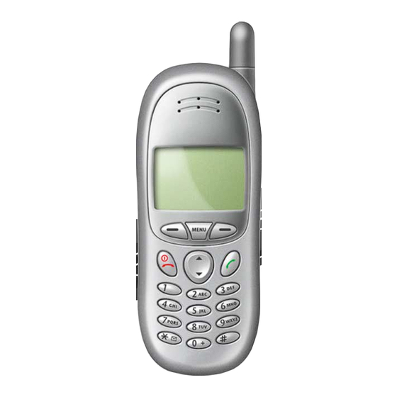
MICROPHONE T191_controls.eps Figure 1. PF C25 Controls and indicators locations The PF C43 Telephone is similar in appearance to the PF C25 telephone but has a slightly different keypad appearance. Function and Keypad Keys The keys on the front of the telephone (in conjunction with the display) provide the phone’s user interface (UI). -
Page 14: General Operation
General Operation Product Family C25 and C43 T191_functkeys.eps Figure 2. PF C25 Function keys August 01, 2001 6881039B15... - Page 15 Level 1 and 2 Service Manual General Operation T191_alpnumkeys.eps Figure 3. PF C25 Alphanumeric keys Liquid Crystal Display (LCD) The LCD provides a high contrast backlit display for easy readability in all light conditions. The large bit-mapped 98 x 64 pixel display includes 3 lines of text, 1 line of icons, and 1 line of soft key labels.
- Page 16 General Operation Product Family C25 and C43 Figure 4 shows the appearance of the PF C25 display when idle. T191_display.eps Figure 4. PF C25 Idle display The phone’s icon indicators are shown in Figure 5. T191_icons.eps Figure 5. PF C25 Icon indicators •...
-
Page 17: User Interface Menu Structure
The menu key opens the initial menu structure, or allows access to a submenu whenever appears on the screen. See Figure 6 for details of the PF C25 menu structure. 6881039B15... - Page 18 General Operation Product Family C25 and C43 T191_mwnu.eps Figure 6. PF C25 Menu structure August 01, 2001 6881039B15...
-
Page 19: Alert Settings
Level 1 and 2 Service Manual General Operation Alert Settings PF C25 and PF C43 telephones include up to 32 preset alert tones and vibrations that can be applied individually to specific alert events or to all events at the same time. - Page 20 General Operation Product Family C25 and C43 August 01, 2001 6881039B15...
-
Page 21: Tools And Test Equipment
Tools and Test Equipment C25 and C43 Tools and Test Equipment The following tables list the tools and test equipment used on the PF C25 telephone. Use either the listed items or equivalents. Table 1. General Test Equipment and Tools... -
Page 22: Disassembly
Disassembly Product Family C25 and C43 Disassembly The procedures in this section provide instructions for the disassembly of PF C25 and PF C43 telephones. Tools and equipment used for the phone are listed in Table 1, preceding. Many of the integrated devices used in this equipment are vulnerable to damage from electrostatic discharge (ESD). -
Page 23: Removing And Replacing The Subscriber Identity Module (Sim)
Level 1 and 2 Service Manual Disassembly Depress the battery latch and slide it in the direction of the arrow (see Figure 7). BATTERY BATTERY LATCH T191_battery_rem.eps Figure 7. Removing the battery Lift the bottom end of the battery from the phone, then remove it completely as shown in the figure. - Page 24 Disassembly Product Family C25 and C43 Rotate the SIM and slide it out as shown in the figure. SIM LATCH T191_SIM_rem.eps Figure 8. Removing the SIM To replace, carefully insert the SIM into the SIM holder. Be sure the SIM is correctly positioned to contact the terminals when closed.
-
Page 25: Removing And Replacing The Rear Escutcheon
Level 1 and 2 Service Manual Disassembly Removing and Replacing the Rear Escutcheon DISASSEMBLY TOOL REAR HOUSING ESCUTCHEON .T191_escutcheon_rem.eps Figure 9. Removing the rear escutcheon Remove the battery as described in the procedures. Using the flat end of the disassembly tool, carefully peel the escutcheon from the rear housing. - Page 26 Disassembly Product Family C25 and C43 Locate the 4 screws holding the front housing to the rear housing. See Figure 10. Push the battery latch in the direction of the arrow to expose the 2 bottom housing screws as shown in Figure 10.
-
Page 27: Removing And Replacing The Antenna
Level 1 and 2 Service Manual Disassembly Slide the battery latch toward the bottom of the phone until it snaps into place. Replace the SIM and battery as described in the procedures. Removing and Replacing the Antenna Remove the battery, SIM, and rear housing as described in the procedures. Using a firm even pressure, pull the antenna straight out of the rear housing to remove. -
Page 28: Removing And Replacing The Vibrator And Vibrator Grommet
Disassembly Product Family C25 and C43 Removing and Replacing the Vibrator and Vibrator Grommet Remove the battery, SIM, and rear housing as described in the procedures REAR HOUSING DISASSEMBLY TOOL VIBRATOR ASSEMBLY VIBRATOR VIBRATOR GROMMET T191_vibrator_rem.eps Figure 12. Removing the vibrator and vibrator grommet Using the flat end of the disassembly tool, carefully pry the vibrator assembly from its cavity in the rear housing as shown in Figure 12. -
Page 29: Removing And Replacing The Alert Transducer Assembly
Level 1 and 2 Service Manual Disassembly Removing and Replacing the Alert Transducer Assembly Remove the battery, SIM, and rear housing as described in the procedures Using the flat end of the disassembly tool, carefully pry the transducer from its cavity in the rear housing as shown in Figure 13. ALERT DISASSEMBLY REAR... -
Page 30: Removing And Replacing The Transceiver Board
Disassembly Product Family C25 and C43 Removing and Replacing the Transceiver Board This product contains static-sensitive devices. Use anti-static handling procedures to prevent electrostatic discharge (ESD) and component damage. Remove the battery, SIM, and rear housing as described in the procedures Using the flat end of the disassembly tool, carefully loosen the transceiver board from the front housing. -
Page 31: Removing And Replacing The Rtc Battery
Level 1 and 2 Service Manual Disassembly Removing and Replacing the RTC Battery Remove the battery, SIM, rear housing, and transceiver board as described in the procedures Use the flat end of the disassembly tool to pry the real time clock (RTC) battery from its socket on the transceiver board. -
Page 32: Removing And Replacing The Keypad
Disassembly Product Family C25 and C43 Removing and Replacing the Keypad Remove the battery, SIM, rear housing, and transceiver board, as described in the procedures DISASSEMBLY TOOL KEYPAD FRONT HOUSING T191_keypad_rem.eps Figure 16. Removing the keypad Lift the keypad from the front housing as shown in Figure 16. -
Page 33: Removing And Replacing The Earpiece Speaker
Level 1 and 2 Service Manual Disassembly Removing and Replacing the Earpiece Speaker Remove the battery, SIM, rear housing, and transceiver board as described in the procedures. EARPIECE SPEAKER DISASSEMBLY TOOL FRONT HOUSING T191_speaker_rem.eps Figure 17. Removing the earpiece speaker Using the flat end of the disassembly tool, pry the earpiece speaker from its cavity in the front housing. -
Page 34: Removing And Replacing The Microphone And Microphone Grommet
Disassembly Product Family C25 and C43 Removing and Replacing the Microphone and Microphone Grommet This product contains static-sensitive devices. Use anti-static handling procedures to prevent electrostatic discharge (ESD) and component damage. Remove the battery, SIM, rear housing, and transceiver board as described in... -
Page 35: Removing And Replacing The Keypad Switch Dome Array
Level 1 and 2 Service Manual Disassembly Align the microphone assembly with the microphone socket press into place until fully seated. The microphone assembly is keyed to fit the microphone socket only one way. Be sure the opening in the microphone grommet is positioned to face the opening in the housing when reassembled. - Page 36 Disassembly Product Family C25 and C43 Apply even pressure across the entire surface of the switch dome array to ensure proper adhesion. Replace the transceiver board, rear housing, SIM, and battery as described in the procedures. Verify correct operation. August 01, 2001...
-
Page 37: Sim Card And Identification
The Mechanical Serial Number (MSN) is an individual unit identity number and remains with the unit throughout the life of the unit. The MSN can be used to log and track a unit on Motorola's Service Center Database. The MSN is divided into 4 sections as shown in Figure 20. - Page 38 SIM Card and Identification Product Family C25 and C43 International Mobile Station Equipment Identity (IMEI) The International Mobile station Equipment Identity (IMEI) number is an individ- ual number unique to the PCB and is stored within the unit's memory. The following diagram illustrates the various parts of this number.
-
Page 39: Troubleshooting
Troubleshooting Troubleshooting Manual Test Mode Motorola PF C25 and C43 telephones are equipped with a manual test mode capability. This allows service personnel to verify functionality and perform fault isolation by entering keypad commands. To enter the manual test command mode, a GSM / DCS test SIM must be used. -
Page 40: Troubleshooting Chart
Troubleshooting Product Family C25 and C43 Troubleshooting Chart Table 3. PF C25 and C43 Telephones: Level 1 and 2 Troubleshooting Chart SYMPTOM PROBABLE CAUSE VERIFICATION AND REMEDY 1. Telephone will not turn on or stay on. a) Battery either discharged or Measure battery voltage across a 50 ohm (>1... - Page 41 Level 1 and 2 Service Manual Troubleshooting Table 3. PF C25 and C43 Telephones: Level 1 and 2 Troubleshooting Chart (Continued) SYMPTOM PROBABLE CAUSE VERIFICATION AND REMEDY b) Transceiver board assembly Replace the transceiver board assembly (refer defective. to 1c). Verify that the fault has been cleared and reassemble with the new transceiver board assembly.
-
Page 42: Programming: Software Upgrade And Flexing
Troubleshooting Product Family C25 and C43 Programming: Software Upgrade and Flexing The following hardware codes must be observed when flashing phones: Hardware Region Code EMEA Asia Contact your local technical support engineer for information about equipment and procedures for flashing and flexing. -
Page 43: Part Number Charts
Level 1 and 2 Service Manual Part Number Charts Part Number Charts The following charts are provided as a reference for the parts associated with PF C25 and C43 telephones. Exploded View Diagram T191_expl_view.eps Figure 22. Exploded View Diagram 6881039B15... -
Page 44: Exploded View Parts List
Part Number Charts Product Family C25 and C43 Exploded View Parts List Table 4. Exploded View Parts List Item Item Part Number Description Part Number Description Number Number see Table 5 Front housing 23.40051.011 Earpiece speaker 23.60021.001 Alert transducer 23.46003.001 Vibrator Assembly 25.90020.001... -
Page 45: Model-Dependent Part Numbers
Keypad English - C43 42.G2202.001 Keypad Traditional Chinese - C43 42.G2202.012 Keypad Simplified Chinese - C43 42.G2202.022 PCB Assembly Main Board - C25 55.G2201.001 PCB Assembly Main Board - C43 55.G1701.001 Transceiver, C25, Graphite Gray S. Asia SUG2137AA Transceiver, C25, Frosted Silver, S. Asia SUG2138AA Transceiver, C25, Moonstone Blue, S. -
Page 46: Accessories
Pouch, Black & Light Grey w/ plastic front MOTFQ0075M Pouch, Light Blue w/velcro MOTPT0076M Pouch, Medium Blue MOTPT0076M Related Publications Motorola Timeport 191 Wireless Phone User Guide, English 9888816L01 Motorola Timeport 190 Wireless Phone User Guide English 9889928L01 August 01, 2001 6881039B15... -
Page 47: Index
1 and 2 Index Level 1 and 2 Service Manual Index C25 and C43 6881039B15 Index identification 32 international mobile station equipment identity 33 mechanical serial number 32 accessories product 1 part numbers 41 IMEI 33 alert modes 15 Introduction 1... - Page 48 Index Product Family C25 and C43 related publications 41 manual test mode commands 34 removing troubleshooting chart 35 alert transducer 24 antenna 22 battery 15 voice recognition 7 earpiece speaker 28 keypad 27 keypad switch dome array 30 microphone 29...
- Page 50 MOTOROLA, the Stylized M Logo, and all other trademarks indicated as such herein are trademarks of Motorola, Inc. ® Reg. U.S. Pat. & Tm. Off. All other product or service names are the property of their respective owners. ã 2001 Motorola, Inc.
Need help?
Do you have a question about the C25 and is the answer not in the manual?
Questions and answers