Motorola C200 Service Manual
D10 dual band wireless telephone
Hide thumbs
Also See for C200:
- User manual (102 pages) ,
- Owner's manual (96 pages) ,
- Service manual (156 pages)

Subscribe to Our Youtube Channel
Related Manuals for Motorola C200


Summary of Contents for Motorola C200
- Page 1 Level 1 and 2 Service Manual Product Family D10 Dual Band Wireless Telephone C200 GSM 900/1800 MHz, GSM 850/1900 MHz...
-
Page 3: Table Of Contents
1 and 2 C200 6809464A58 Level 1 and 2 Service Manual Contents Contents Contents Introduction ................4 Product Identification . -
Page 4: Introduction
Available on a contract basis, Motorola Inc. offers comprehensive maintenance and installation programs which enable customers to meet requirements for reliable, continuous communications. To learn more about the wide range of Motorola service programs, contact your local Motorola products representative or the nearest Customer Service Manager. Product Identification Motorola products are identified by the model number on the housing. -
Page 5: Computer Program Copyrights
The Motorola products described in this manual may include Motorola computer programs stored in semiconductor memories or other media that are copyrighted with all rights reserved worldwide to Motorola. Laws in the United States and other countries preserve for Motorola, Inc. certain exclusive rights to the copyrighted... -
Page 6: Warranty Service Policy
Customer’s original units will be repaired but not refurbished as standard. Appointed Motorola Service Hubs will perform warranty and non-warranty field service for level 2 (assemblies) and level 3 (limited PCB component). The Motorola High Tech Centers will perform level 4 (full component) repairs. -
Page 7: Parts Replacement
When ordering crystals or channel elements, specify the Motorola part number, description, crystal frequency, and operating frequency desired. When the Motorola part number of a component is not known, use the product model number or other related major assembly along with a description of the related major assembly and of the component in question. -
Page 8: Specifications
Specifications C200 Specifications General Function Specification Frequency Range GSM 900 880-915 MHz Tx (with EGSM) 925-960 MHZ Rx Frequency Range DCS 1800 1710-1785 MHz Tx 1805-1880 MHz Rx Channel Spacing 200 kHz Channels 174 EGSM Modulation GMSK at BT = 0.3... -
Page 9: Product Overview
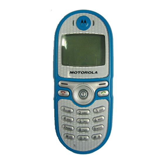
MHz bands. C200 telephones support SMS in addition to traditional circuit switched transport technologies. C200 telephones are made of a polycarbonate plastic. The display and speaker, as well as the keypad, transceiver printed circuit board (PCB), microphone, external accessory connector, volume buttons, power button, and voice button, are contained within the candy bar form-factor housing. - Page 10 HTML (subsequently filtered to WML) or directly in WML if available. The information is then passed to the mobile subscriber via the mobile network. The C200’s microbrowser can be configured for baud, idle timeout, line type, phone number, and connection type.
- Page 11 • Divert incoming data calls • Allow all calls through to the phone. Detailed operating instructions for these and the other C200 features can be found in the appropriate C200 telephone user’s guides listed in the “Related Publications” section toward the end of this manual.
-
Page 12: General Operation
General Operation Controls, Indicators, and Input / Output (I/O) Connectors The C200 telephone controls are located on the keyboard. The headphone jack and power jack are on the side and bottom, respectively. Indicators, in the form of icons, are displayed on the LCD (see Figures 2 and 3). - Page 13 Turn animation off to conserve the battery. ➧ Whether a phone displays all indicators depends on the programming and services to which the user subscribes. Figure 2 shows the appearance of the C200 display when idle. h b Ðf a Status icon bar &...
- Page 14 General Operation C200 The phone’s icon indicators are shown in Figure 3. 010716-o Figure 3. Icon Indicators • Signal Strength Indicator. Shows the strength of the phone’s connection with the network. Calls cannot be sent or received when the “no signal”...
-
Page 15: User Interface Menu Structure
Alert Settings C200 telephones include up to 32 preset alert tones and vibrations that can be applied individually to specific alert events or to all events at the same time. -
Page 16: Operation
General Operation C200 Operation For detailed operating instructions, refer to the appropriate User’s Guide listed in the Related Publications section toward the end of this manual. May 21, 2003 6809464A5-O... -
Page 17: Tools And Test Equipment
Digital Multimeter Used to measure battery voltage 1. To order in North America, contact Motorola Aftermarket and Accessories Division (AAD) at (847) 538-8000; Internationally, AAD can be reached by calling (847) 538-8023 or faxing (847) 576-3023. 2. Not available from Motorola. To order, contact Hewlett Packard at (800) 452-4844. -
Page 18: Disassembly
C200 Disassembly The procedures in this section provide instructions for the disassembly of C200 telephones. Tools and equipment used for the phone are listed in Table 1. Many of the integrated devices used in this equipment are vulnerable to damage from electrostatic discharge (ESD). -
Page 19: Removing And Replacing The Battery
Level 1 and 2 Service Manual Disassembly Removing and Replacing the Battery All batteries can cause property damage and/or bodily injury such as burns if a conductive material such as jewelry, keys, or beaded chains touch exposed terminals. The conductive material may complete an electrical circuit (short circuit) and become quite hot. -
Page 20: Removing And Replacing The Subscriber Identity Module (Sim)
Disassembly C200 Removing and Replacing the Subscriber Identity Module (SIM) Remove the battery cover and battery as described in the procedures. Slide the SIM latch in the direction of the arrow to unlock as shown in Figure 6. Slide the SIM out as shown in the figure. -
Page 21: Removing And Replacing The Endo Assembly
Level 1 and 2 Service Manual Disassembly Lift the top end of the antenna cover away from the phone. Be careful not to damage the lanyard loop at the top end of the phone. To replace, align the antenna cover to the phone. Attach the top end of the antenna cover to the top of the phone. -
Page 22: Removing And Replacing The Front Endo Assembly
Disassembly C200 Using the flat end of the disassembly tool, carefully disengage the catches on each side of the housing, then carefully separate the endo assembly from the front housing. To replace, align the endo assembly to the front housing then firmly press together until the catches engage and the housings are properly assembled. -
Page 23: Removing And Replacing The Vibrator Motor
Level 1 and 2 Service Manual Disassembly Removing and Replacing the Vibrator Motor Remove the battery cover, battery, SIM, endo assembly, and front endo assem- bly as described in the procedures 2. Use the disassembly tool to carefully pry the vibrator motor from its location in the rear endo assembly as shown in Figure 10 The assembly should come... -
Page 24: Removing And Replacing The Transceiver Board
Disassembly C200 Removing and Replacing the Transceiver Board This product contains static-sensitive devices. Use anti-static handling procedures to prevent electrostatic discharge (ESD) and component damage. Remove the battery cover, battery, SIM, antenna cover, and rear endo as described in the procedures... -
Page 25: Removing And Replacing The Keypad
Level 1 and 2 Service Manual Disassembly Removing and Replacing the Keypad Remove the battery, SIM, rear housing, and transceiver board, as described in the procedures Plastic Tweezers Keypad Front Housing 031329o Figure 12. Removing the Keypad Lift the keypad from the front housing as shown in Figure 12. To replace, insert the keypad into the front housing. -
Page 26: Removing And Replacing The Earpiece Speaker
Disassembly C200 Removing and Replacing the Earpiece Speaker Remove the battery, SIM, rear housing, and transceiver board as described in the procedures. Upper Endo Earpiece Speaker Figure 13. Removing the Earpiece Speaker Using the flat end of the plastic tweezers, push the earpiece speaker from its cavity in the upper endo as shown in Figure 17. -
Page 27: Removing And Replacing The Microphone
Level 1 and 2 Service Manual Disassembly Removing and Replacing the Microphone This product contains static-sensitive devices. Use anti-static handling procedures to prevent electrostatic discharge (ESD) and component damage. Remove the battery, SIM, rear housing, and transceiver board as described in the procedures Upper Endo Microphone... -
Page 28: Sim Card And Identification
The Mechanical Serial Number (MSN) is an individual unit identity number and remains with the unit throughout the life of the unit. The MSN can be used to log and track a unit on Motorola's Service Center Database. The MSN is divided into 4 sections as shown in Figure 15. - Page 29 Level 1 and 2 Service Manual SIM Card and Identification Table 2. IMEI Number Breakdown Serial Check digit Number NNXXXX YY ZZZZZZ Where Type Allocation Code, formerly known as Type Approval Code NNXXXX Type Identifier YY is set to 00 from 01/01/2003 until 31/03/2004 ZZZZZZ Individual unit serial number Phase 1 = 0.
-
Page 30: Troubleshooting
C200 Troubleshooting Manual Test Mode Motorola C200 telephones are equipped with a manual test mode capability. This allows service personnel to verify functionality and perform fault isolation by entering keypad commands. To enter the manual test command mode, a GSM test SIM must be used. -
Page 31: Troubleshooting Chart
Level 1 and 2 Service Manual Troubleshooting Troubleshooting Chart Table 4. C200 Telephones: Level 1 and 2 Troubleshooting Chart SYMPTOM PROBABLE CAUSE VERIFICATION AND REMEDY 1. Telephone will not turn on or stay on. a) Battery either discharged or Measure battery voltage across a 50 ohm defective. - Page 32 Troubleshooting C200 Table 4. C200 Telephones: Level 1 and 2 Troubleshooting Chart (Continued) SYMPTOM PROBABLE CAUSE VERIFICATION AND REMEDY b) Transceiver board assembly Replace the transceiver board assembly defective. (refer to 1c). Verify that the fault has been cleared and reassemble with the new transceiver board assembly.
-
Page 33: Programming: Software Upgrade And Flexing
Level 1 and 2 Service Manual Troubleshooting Programming: Software Upgrade and Flexing Contact your local technical support engineer for information about equipment and procedures for flashing and flexing. 6809464A58 May 21, 2003... -
Page 34: Part Number Charts
Part Number Charts C200 Part Number Charts The following charts are provided as a reference for the parts associated with C200 telephones. Exploded View Diagram Figure 16. C200 Exploded View Diagram May 21, 2003 6809464A58... -
Page 35: Exploded View Parts List
Dispose of used batteries according to the manufacturer’s instructions. You can use the following link to order parts: https://wissc.motorola.com/wissc_root/main/BrowserOK.html A password is required. For information on ordering parts for EMEA region please call +44 131 479 1274... -
Page 36: Accessories
Part Number Charts C200 Accessories Table 6. Accessories Part Description Part Number Headset Ear bud – Silver AAYN4264A Lanyard SYN8392 Related Publications Motorola C200 Wireless Phone User Guide, English May 21, 2003 6809464A58... -
Page 37: Index
1 and 2 Index Level 1 and 2 Service Manual Index C200 6809464A58 international mobile station equipment identity 28 mechanical serial number 28 accessories product 4 part numbers 36 IMEI 28 alert modes 15 Introduction 4 antenna cover removing 20... - Page 38 Index C200 microphone 27 SIM card 20 transceiver board 24 replacing antenna 22 battery cover 18 earpiece speaker 26 keypad 25 microphone 27 serial number mechanical 28 service manual about 5 scope 5 service policy 6 customer support 6 out of box failure 6...
- Page 40 MOTOROLA, the Stylized M Logo, and all other trademarks indicated as such herein are trademarks of Motorola, Inc. ® Reg. U.S. Pat. & Tm. Off. All other product or service names are the property of their respective owners. 2003 Motorola, Inc.
Need help?
Do you have a question about the C200 and is the answer not in the manual?
Questions and answers