Table of Contents
Advertisement
Advertisement
Table of Contents

Summary of Contents for JSG M2AP01
- Page 1 OPERATION & INSTALLATION MANUAL FOR ALARM PANEL M2AP01...
-
Page 2: Table Of Contents
Table of Contents Safety Instructions Owner/Operator Responsibility Specifications Introduction Installation Instructions Setup Wiring Wiring Diagram for MusterWire LHD Installations Wiring Diagram for LOP Installations Battery Expansion Data Port Operation Isolated Mode Standby Mode (OK Mode) Fault Mode Fire Mode: LHD Installations Fire Mode: LOP Installations Page 2... -
Page 3: Safety Instructions
SAFETY INSTRUCTIONS Read and carefully observe these operation and installation instructions before unpacking and operating the Muster Fire Suppression Systems. The valve must be operated, maintained and repaired exclusively by persons familiar with the operating instructions. Local safety regulations regarding installation, operation and maintenance must be followed. IMPORTANT Operate this equipment only DO NOT alter or modify any part of... -
Page 4: Specifications
SPECIFICATIONS Specifications Ingress Protection IP66 Battery 15V 1.5Ah Lithium Manganese Dioxide with internal fuse Battery Life Min 2 years + 6 months warning Operating Temperature -40°C to + 70°C (Celsius) Dimensions DIA 97mm depth 55mm (housing only) Cable 1.1meter 10 core x 0.75mm Buzzer 98dB @ 1 meter in free air Outputs... -
Page 5: Introduction
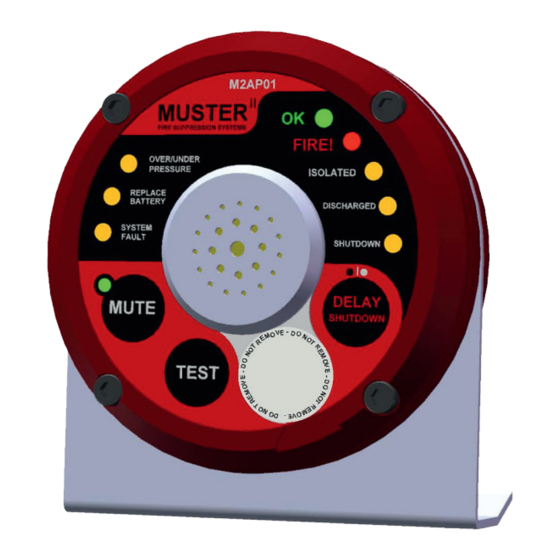
INTRODUCTION The Muster Alarm Panel (M2AP01) is an advanced integrated control for the monitoring, control and activation of Muster Fire Suppression Systems. Used in conjunction with the various Muster pressure transducers, actuators and detectors this provides a flexible and complete solution to fire protection. -
Page 6: Installation Instructions
INSTALLATION INSTRUCTIONS The M2AP01 fire detection Alarm Panel can be used on two distinct types of installation: MusterWire LHD Installations In MusterWire LHD (Linear Heat Detection) installations; the Alarm Panel electrically monitors for fire using MusterWire LHD (heat detection wire) and automatically activates the discharge of the system as well as providing alarm, monitoring and shutdown functions. - Page 7 RIGHT BANK Shutdown Delay: DIP switches 1, 2 and 3 are used to select the delay between detection of a fire and the activation of the Shutdown Circuit. The times indicated on the individual switches are added together giving a total of 8 possible settings from 0 to 36 seconds in 6 second steps.
-
Page 8: Wiring
WIRING Wiring of the Muster fire detection system and associated peripherals is simple with a maximum of five circuits, each requiring only a single pair of wires. Wires from the Alarm Panel are pre-paired, colour coded and marked. Only the pressure transducer circuit is polarised, the remaining four circuits having no polarity. - Page 9 Page 9...
-
Page 10: Wiring Diagram For Musterwire Lhd Installations
Page 10... -
Page 11: Wiring Diagram For Lop Installations
IMPORTANT Use of proper safety wear and tools is highly recommended to help prevent injury to self and damage to the equipment. ALARM RELAY CIRCUIT: (Optional for both MusterWire LHD and LOP systems) This circuit connects to voltage free relay terminals inside the Alarm Panel. This relay is energised when a fire is detected and the contacts can be used for connecting to other systems such as telemetry or external fire alarms. -
Page 12: Battery
BATTERY This Alarm Panel operates independently of any external power supply and uses an advanced non-rechargeable lithium battery pack to drive all functions including energising the release solenoids. The pack has built-in circuitry that allows it to accurately keep track of its charge state and will notify the Alarm Panel that it needs replacement once 60% of its capacity has been used up. -
Page 13: Expansion
EXPANSION The Pressure transducer circuit uses an addressing protocol that will allow for the attachment of other devices on the same line such as hydraulic pressure relief valves or advanced telemetry systems such as GSM modems. Consult your dealer to find out what accessories are available. DATA PORT The Alarm Panel incorporates a data port on the back to accommodate extended functions. -
Page 14: Operation
OPERATION MusterWire LHD Alarm Panel Configuration LOP Alarm Panel Configuration The panel operates in a number of possible states depending on the conditions and settings: Isolated Mode - system is isolated (only available on MusterWire LHD installations) Standby Mode - system is functioning correctly ... -
Page 15: Isolated Mode
ISOLATED MODE This mode is selected using the DIP switch located inside the lid of the panel and is generally used to isolate the system during maintenance. Since the panel has no control of the discharge function in LOP systems this function is not enabled on LOP installations to avoid possible confusion. -
Page 16: Fault Mode
FAULT MODE The Alarm Panel is able to detect a number of faults conditions. Most fault conditions are latched and can only be cleared by pressing the TEST button. This ensures that intermittent faults do not go unnoticed. Once a fault is latched the appropriate indicator will blink and the audible alarm will give a short pip every 3 seconds and the OK indicator will be off. -
Page 17: Fire Mode: Lhd Installations
FIRE MODE: MUSTERWIRE LHD INSTALLATIONS In MusterWire LHD installations the Alarm Panel will detect a fire if any of the following conditions are met: Automatic activation of the MusterWire Linear Heat Detection as a result of excessive heat. Manual activation of a Remote Actuator (M2RA01) attached to the detector circuit. ... -
Page 18: Fire Mode: Lop Installations
FIRE MODE : LOP INSTALLATIONS In LOP installations the Alarm Panel monitors the pressure in the system and assumes a fire condition if the pressure drops rapidly. Once activated the Alarm Panel goes through a strict sequence of events as follows: The ALARM relay contacts are activated. - Page 19 Notes Page 19...
- Page 20 Cylinder Filling Manual, M2CM01 June 2013...
Need help?
Do you have a question about the M2AP01 and is the answer not in the manual?
Questions and answers