Sign In
Upload
Download
Table of Contents
Contents
Add to my manuals
Delete from my manuals
Share
URL of this page:
HTML Link:
Bookmark this page
Add
Manual will be automatically added to "My Manuals"
Print this page
×
Bookmark added
×
Added to my manuals
Manuals
Brands
THERMOROSSI Manuals
Boiler
aspiromec le
Installation, use and maintenance manual
THERMOROSSI aspiromec le Installation, Use And Maintenance Manual
Hide thumbs
1
2
Table Of Contents
3
4
5
6
7
8
9
10
11
12
13
14
15
16
17
18
19
20
21
22
23
24
25
26
27
28
29
30
31
32
page
of
32
Go
/
32
Contents
Table of Contents
Troubleshooting
Bookmarks
Table of Contents
Table of Contents
Ce Declaration of Conformity
1 Introduction
General Guidelines
Safety Guidelines
Standards and Recommendations
Transportation
General Warnings
3 General Description
2 Technical Characteristics
Technical Data
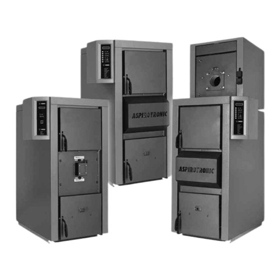
ASPIROTRONIC LE / ASPIROMEC LE Wood Fired Boilers
4 Installation
Mounting the Outer Casing on ASPIROTRONIC LE ASPIROMEC LE
Mounting the Outer Casing on ASPIROTRONIC COMBI LE
Mounting the Electronic Panel on ASPIROTRONIC LE
Functions of Panel on ASPIROTRONIC LE
Display Panel of ASPIROTRONIC
Programs of the ASPIROTRONIC LE Panel
Electrical Connections Diagram for ASPIROTRONIC LE
Diagram of ASPIROTRONIC LE Electronic Panel
Remote Board Control
Installation of the Antenna
Installation of ASPIROMEC LE Electromechanical Panel
ASPIROMEC LE Electromechanical Panel Functions
Wiring Diagram for ASPIROMEC LE
Electrical Connections Diagram for ASPIROMEC LE
Installation of Smoke Suction Unit on ASPIROMEC LE / ASPIROTRONIC LE
Installation of Safety Exchanger/Heat Exchanger on ASPIROMEC LE/ASPIROTRONIC LE (Optional)
Guidelines for the Hydraulic Connections of the LE Series Boilers
Guidelines for the Hydraulic Connections of the ASPIROTRONIC COMBI LE Boiler (Optional)
Guidelines for the Hydraulic Connections of the ASPIROTRONIC LE / ASPIROMEC LE Boiler with the Boiler Tube (Optional)
Example of Hydraulic Diagram for ASPIROTRONIC LE with DUO-TEC Settings
Example of Hydraulic Diagram for ASPIROTRONIC LE with PUFFER-TEC Settings
Approximate Hydraulic Diagram of ASPIROTRONIC LE with Puffer with First Priority to Heating System
Starting the ASPIROMEC LE Boiler
Starting the ASPIROTRONIC LE Boiler
5 Use of the Boiler
Refuelling with Wood
Adjustment of the Combustion Air Damper Opening
Practical Advice and Guidelines
Wood Fuel
6 Troubleshooting
Troubleshooting for ASPIROMEC LE and ASPIROTRONIC LE Boilers
7 Cleaning and Maintenance
Cleaning and Maintaining EURA Boilers
Advertisement
Quick Links
1
Mounting the Electronic Panel on Aspirotronic le
2
Display Panel of Aspirotronic
3
Electrical Connections Diagram for Aspirotronic le
4
Refuelling with Wood
5
Troubleshooting for Aspiromec le and Aspirotronic le Boilers
6
Troubleshooting
Download this manual
H E A T I N G T E C H N O L O G Y A N D I N N O V A T I O N
INSTALLATION, USE AND MAINTENANCE GUIDE
Table of
Contents
Previous
Page
Next
Page
1
2
3
4
5
Advertisement
Table of Contents
Need help?
Do you have a question about the aspiromec le and is the answer not in the manual?
Ask a question
Questions and answers
Related Manuals for THERMOROSSI aspiromec le
Boiler THERMOROSSI aspirotronic le Installation, Use And Maintenance Manual
(32 pages)
Boiler THERMOROSSI ECOTHERM H20 14 Installation, Use And Maintenance Manual
Thermorossi ecotherm h20 14 boiler (38 pages)
Boiler THERMOROSSI Bosky Boffing 6 Installation And Operating Instructions Manual
(27 pages)
Boiler THERMOROSSI Bosky 60 Installation And Operating Instructions Manual
(22 pages)
Boiler THERMOROSSI Ecotherm H2O Installation, Use And Maintenance Manual
(36 pages)
Boiler THERMOROSSI ECOTHERM H20 18 Installation, Use And Maintenance Manual
(41 pages)
Boiler THERMOROSSI COMPACT S32 CLASS 5 Instruction Manual
Pellet boiler (61 pages)
Boiler THERMOROSSI LAMBDA S29 EVO5 Installation, Use And Maintenance Manual
(44 pages)
This manual is also suitable for:
Aspirotronic combi le
Aspirotronic le
Table of Contents
Print
Rename the bookmark
Delete bookmark?
Delete from my manuals?
Login
Sign In
OR
Sign in with Facebook
Sign in with Google
Upload manual
Upload from disk
Upload from URL


Need help?
Do you have a question about the aspiromec le and is the answer not in the manual?
Questions and answers