Table of Contents
Advertisement
2000
2000
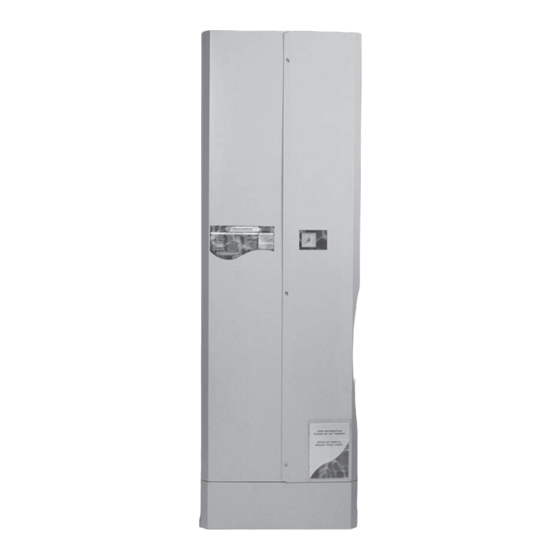
ELECTRAMATE
ELECTRAMATE
DESIGN, INSTALLATION AND
SERVICING INSTRUCTIONS
PLEASE LEAVE THESE INSTRUCTIONS IN THE POCKET PROVIDED ON
THE BACK OF THE FRONT PANEL
Gas Council Approved Reference Numbers
ElectraMate 270 97-317-36
ElectraMate 170 97-317-37
benchmark
TM
A COMBINED PRIMARY STORAGE UNIT (CPSU) FOR
DOMESTIC HOT WATER SUPPLY AND CENTRAL
The code of practice for the installation,
HEATING UTILISING OFF-PEAK ELECTRICITY
commissioning & servicing of central heating systems
ALL MODELS COMPLY WITH THE
WATER HEATER MANUFACTURERS SPECIFICATION
FOR INTEGRATED THERMAL STORES
Supplied By www.heating spares.co Tel. 0161 620 6677
Advertisement
Table of Contents

Related Manuals for gledhill ElectraMate 2000


Summary of Contents for gledhill ElectraMate 2000
-
Page 1: Servicing Instructions
2000 2000 ELECTRAMATE ELECTRAMATE DESIGN, INSTALLATION AND SERVICING INSTRUCTIONS PLEASE LEAVE THESE INSTRUCTIONS IN THE POCKET PROVIDED ON THE BACK OF THE FRONT PANEL Gas Council Approved Reference Numbers ElectraMate 270 97-317-36 ElectraMate 170 97-317-37 benchmark A COMBINED PRIMARY STORAGE UNIT (CPSU) FOR DOMESTIC HOT WATER SUPPLY AND CENTRAL The code of practice for the installation, HEATING UTILISING OFF-PEAK ELECTRICITY... -
Page 2: Table Of Contents
Quality System audited by BSI. Patents Pending The Gledhill Group’s first priority is to give a As part of the industry wide “Benchmark” Initiative all Gledhill ElectraMates now high quality service to our customers. include a Benchmark Installation, Commissioning and Service Record Log Book. -
Page 3: Design
BS6798, BS5449, BS5546, BS5440:1, BS5440:2, CP331:3, BS6700, BS5258, BS7593 and BS7671. Although the domestic water supply to the ElectraMate 2000 is at mains pressure, it is not necessary to fit an expansion vessel, pressure or temperature relief valve. The ElectraMate 2000 is available for use with sealed primary central heating systems. - Page 4 1.0 DESIGN 1.1 INTRODUCTION Key to Schematic Automatic air vent Anti-vacum valve Blending valve Heating pump PHE pump Plate heat exchanger DHW sensor PHE return sensor Hot water outlet Mains cold water inlet 90º angle isolating ballvalve CA type backflow prevention valve - discharging into a tundish Filling pressure regulating valve Heating flow Heating return...
- Page 5 1.1 INTRODUCTION Space Heating Operation The ElectraMate 2000 has been designed to utilize the latest technology to provide mains pressure hot water and traditional wet central heating from conventional radiators utilising off-peak electricity.Two sizes are available to suit different property...
-
Page 6: Issue 4
1.0 DESIGN 1.2 TECHNICAL DATA r t i l l u r i c c i t r i c c i t l l i r i c ½ " i n I a i t i n I a i t t i l °... - Page 7 1.0 DESIGN 1.2 TECHNICAL DATA Standard Equipment The standard configuration of the ElectraMate 2000 is shown opposite. The Appliance Control Board (A.C.B.), mounted inside the appliance, controls the operation of the complete system. It is supplied with the following factory fitted equipment:- Automatic air vent Anti-vacuum valve...
- Page 8 1.0 DESIGN 1.2 TECHNICAL DATA 40 ltr. expansion 25 ltr. vessel for vessel EM 170 model = 320 dia. 290mm dia. x 500mm APPLIANCE DIMENSIONS Height Width Depth Model EM 170 1350mm 595mm 595mm EM 270 1910mm 595mm 595mm The following table of minimum cupboard dimensions only allow the minimum space required for the appliance (including the expansion vessel) and any extra space required...
- Page 9 1.0 DESIGN 1.2 TECHNICAL DATA ����� It is easier if all pipes terminate vertically in the positions shown opposite. Compression or push fit connections can be used and we do offer a set of flexible connectors as an option. All pipe positions are approximate and subject to a tolerance of ±...
-
Page 10: System Details
1.0 DESIGN 1.3 SYSTEM DETAILS A schematic arrangement of the wiring in the ElectraMate is shown below. To ensure efficient operation of the appliance it is important that discussions take place with the Electrical Supply Authority to ensure that the best off peak supply/tariff is utilized. When designing the electrical system reference should be made to the latest issue of the IEE Requirements for Electrical Installations and... - Page 11 1.0 DESIGN 1.3 SYSTEM DETAILS Electrical connections to the appliance for the Installer 2000 ElectraMate Low current Supply Programmable Room off-peak signal Thermostat Wiring Guide AC30 BS1361 TYPE1 FUSE LINK 450 V PA 44 450 V PA 44 Remove link after fitting Programmable room thermostat 1.
- Page 12 Hot Water Systems the installer should check the hardness level of the water supply and if The hot water flow rate from the ElectraMate 2000 is directly related to the adequacy necessary fit an in-line scale inhibitor/reducer of the cold water supply to the dwelling. This must be capable of providing for those...
- Page 13 BS 6700. directly from the ElectraMate 2000 or be the first draw-off point on the hot circuit. The However, the following rule of thumb guide lines should be adequate for most...
- Page 14 ElectraMate 2000 and is piped in the conventional manner. EM 2000 The ElectraMate 2000 is only suitable for a sealed heating system. Therefore heating circuit pipework can run at a higher level than the appliance if required as long as suitable air vents are provided.
- Page 15 = Height of Tundish Filling the Heating System Le = Total equivalent length of discharge pipe (M) The ElectraMate 2000 appliance comes Note : 90° bend is equivalent to 1M of straight pipe complete with a CA type backflow prevention...
- Page 16 1.0 DESIGN 1.3 SYSTEM DETAILS Expanson vessel requirements The ElectraMate 2000 Model EM270 is supplied with a 40 litre expansion vessel and the model EM170 is supplied with a 25 litre expansion vessel. Both are supplied pre-charged to 1.0 bar to accommodate the expansion of total water content of the system including thermal store.The size of the expansion vessel provided...
-
Page 17: Installation
A suitable location will be needed for the separate expansion vessel. This will often be at high level in the cupboard housing the ElectraMate 2000 but can be at a remote position if required. The dimensions and clearances are provided in section 1.2 Technical Data. -
Page 18: Installation
2.0INSTALLATION 2.2 INSTALLATION Preparation/placing the appliance in position. Details of the recommended positions for termination of the first fix pipework are provided in section 1.2 Technical Data. The pipework can be located or its position checked using the template provided with each appliance. If these have been followed installation is very simple and much quicker than any other system. - Page 19 2.0INSTALLATION 2.2 INSTALLATION Pipework connections The position of the pipework connections is shown opposite. The connection sizes and dimensions are listed in Section 1.2 Technical Data. All the connections are also labelled on the appliance. It is essential that the pipework is connected to the correct connection.
-
Page 20: Wiring Diagram
2.0INSTALLATION 2.2 INSTALLATION 2000 PHE Return Sensor ElectraMate DWH Sensor Wiring Diagram Store Sensor Wiring Key Brown Blue Green/Yellow Black 1 2 3 4 5 Boiler Overheat Thermostat Dual Heating L N E Element Pump L N E Heating Pump AC30 AC30 Mains... - Page 21 TP5E Before commencing the wiring,ensure that the PROGRAMMABLE ROOM THERMOSAT power source to which the ElectraMate 2000 is to be connected is isolated and checked with approved and certified test equipment. Remove the front panel. The appliance is supplied with a 3 metre x 10mm²...
- Page 22 2.0 INSTALLATION 2.2 INSTALLATION Wiring the system (contd.) Before switching on the electrical supply check all the factory made terminal connections to ensure they have not become loose during transit. Note : The appliance is provided with a 4.0mm earth cable from an earthing strap on the primary return (to boiler) pipe to the earth stud on the wiring panel.
-
Page 23: Commissioning
Section 10. the pressure regulating and CA type backflow prevention valves provided as part of the ElectraMate 2000. Add inhibitor to the system in the normal way whilst the If in any doubt please consult our Technical ). system is filling. Once full check the whole of the primary heating and domestic hot and cold distribution systems for leaks - See Section 10. - Page 24 2.0 INSTALLATION Mixing valve 2.3 COMMISSIONING Thermal store Heating pump BAR 5 - OFF PEAK ON Sensor T1 BAR 6 - WINTER SWITCH ON Heating circuit Heat Boiler pump exchanger pump BAR 1 - HT ON BAR 2 - ST ON Sensor T3 Elec.
- Page 25 2.0 INSTALLATION 2.3 COMMISSIONING Powering the system/appliance The appliance will automatically commission when it is switched on. However it is essential that the following steps are carried out to check the correct functioning of all the controls. Before switching ON the mains supply to the appliance check that : 1.
- Page 26 LED 2 will switch off. this appliance. The ElectraMate 2000 has a SUMMER/WINTER switch. These Instructions should be placed along with During the months when heating is not required, switch to summer mode. This...
-
Page 27: Servicing
3.0 SERVICING 3.1 ANNUAL SERVICING No annual servicing of the ElectraMate 2000 is necessary. However, we would recommend that checks on the appliance controls and a hot water performance test are carried out annually to prove the appliance is working satisfactorily and within its specification. -
Page 28: Short Parts List
3.0 SERVICING 3.3 SHORT PARTS LIST l i c " 2 f e i l i a c i t " 2 c i t r i a i r t l i o ' l l x i f t i l i l e t i l... - Page 29 3.0 SERVICING 3.3 SHORT PARTS LIST 14/15 Page 29 Supplied By www.heating spares.co Tel. 0161 620 6677...
-
Page 30: Fault Finding
3.0 SERVICING FAULTS AND THEIR CAUSES 3.4 FAULT FINDING 9. If 1 to 8 are correct then it is likely that Any fault in the system design or malfunction of system components will generate the performance of the heat exchanger is customer complaints. - Page 31 3.0 SERVICING 3.4 FAULT FINDING The operation of the ACB itself can be checked as follows : • Switch off mains. • Check/insert correct jumpers i.e. across 2 and 4. • Insert jumper 5. • Switch on mains. • The PCB will carry out functional tests and then stop.
- Page 32 3.0 SERVICING The ACB can be used to establish/check the operating and set temperatures of the appliance as well as identify faults on any of the 3 sensors. This is done by operating switches SW1 and SW2 as shown opposite and reading the LED display.
-
Page 33: Appendix A
APPENDIX A WATER SAVINGS WATER RELATED COSTS CAN BE REDUCED BY GOOD PLUMBING PRACTICE. TAPS & MIXERS 2 TAP 5, 6 OR HALF OPEN OVER 8 L/M 20 L/M Unregulated Fitted with regulator SHOWERS 4 FIXING OPTIONS FOR TAPS & MIXERS 1. -
Page 34: Appendix B
APPENDIX B MANIFOLDS Two sets of manifolds are available as an optional extra. Each set comprises a separate hot and cold water manifold. Both are provided with a 22mm inlet connection t t i t i l located centrally. All outlet connections are 15mm compression. - Page 35 APPENDIX B The pressure loss through a flow regulator at the designated flow rate is about 1.8 bar. Therefore for the flow regulator to control the flow rate at pre-set level,the inlet pressure must be greater than 1.8 bar. If the inlet pressure is lower, the flow rate will be correspondingly less than the pre-set values.
- Page 36 APPENDIX B The size of the distribution pipes supplying the manifold should be calculated using the method set out in BS 6700. A typical diagrammatic arrangement of a system using Manifold Type 1 is shown below. This is only meant to show the principles involved and the actual connection of fittings to the manifold will need to suit the arrangements shown on page 35.
-
Page 37: Appendix C
APPENDIX C G U I D A N C E N O T E S Inhibitor (Corrosion & scale protection of primary heating circuit) On filling the heating system and before the boiler is fired up, it is important to ensure the system water is treated with a suitable corrosion inhibitor, in accordance with the boiler manufacturer’s instructions. -
Page 38: Appendix D
APPENDIX D ������ �������� �� ��������� �������� �� ������ ��� ���� ��� ���� ������ �� ����������� ���� ���� ��� ������ �� �������� ��� ����� �������� ������ ���� ��� ������ �������� ����� ��� ������������ �� ���������� �� � ���� ���������� �������� ������... -
Page 39: Terms & Conditions
�������� ��� ������ �������� ���� �������� ���� ���������� �� ���� � �������� ����� �� �� ���� �� �������� ���� ��� ���������� ����� ������ ����� ��� �� ������ ������ �� �� ����� �� ��� �� ��� ���� �� ������� �� ���� ���� �� �������� ������� ��������... - Page 40 ��� �� ��� ����� ���� ��� ��������� ����� ���� ��� �� ��� ����� ��� ��� ����� ��������� �� ��� ��������� ���� ��� ����� ��� ��������� �� ������� ����� �� � �� ����� �������� �� �������� �� ������ ��� ������� ��� ��������� ����� ��������� ��������...
- Page 41 Supplied By www.heating spares.co Tel. 0161 620 6677...
- Page 42 Supplied By www.heating spares.co Tel. 0161 620 6677...
- Page 43 Supplied By www.heating spares.co Tel. 0161 620 6677...
- Page 44 Supplied By www.heating spares.co Tel. 0161 620 6677...
Need help?
Do you have a question about the ElectraMate 2000 and is the answer not in the manual?
Questions and answers