Table of Contents
Advertisement
Advertisement
Table of Contents

Related Manuals for Accutome a-scan plus


Summary of Contents for Accutome a-scan plus
-
Page 3: Table Of Contents
Optional Components....................4 About this Manual ...................4 Chapter 2: Safety ..................6 Safety Information ..................6 Safety Issues to Consider When Using the Accutome A-Scan Plus.....6 Indications for use....................6 Symbols Definitions for the Accutome..............7 Safety Precautions ...................8 Sterilization......................8 Disinfection and Cleaning..................9 Electrical Hazard and Safety................10 Avoiding Equipment Damage................10... - Page 4 Accutome Probe with Goldman Tonometer Adapter..........21 Accutome Probe with Handle Extension.............22 Basic Operation ....................24 How to Power On the Accutome A-Scan Plus............24 How to Adjust the Contrast.................25 Using the Test Block....................26 Preparation of Patient for Examination...............27 How to Start a New Patient.................27 How to Enter Text without a Keyboard...............31...
- Page 5 Pre-entered Fields....................52 Fields Requiring Information................53 Numeric Fields....................53 Keyboard Shortcuts ..................53 Using the Footswitch ..................55 Setting Up the Accutome A-Scan Plus ...........56 Chapter 5: Preferences ..............56 How to Access Preferences .................57 Top Level of Preferences..................58 How to Add a New Eye Type ..............59...
- Page 6 How to Set the K Index..................111 How to Set the IOL Step...................114 How to Activate the Network Folder..............118 Configure Network Folder................119 Testing Network Connection on the A-Scan Plus..........123 Connect to the PC folder..................123 Troubleshooting the problems................123 How to Adjust the Date and Time..............124 How to Set the Auto Mode ................127...
- Page 7 Capture Modes .....................144 Auto Mode......................144 Manual Mode....................145 How to Capture a Waveform ..............145 Using the Footswitch..................145 Using the Running/Frozen Button..............145 Using the Measure Button.................146 How to Select a Measurement ..............146 Selecting a Measurement with the Knob............146 Selecting a Measurement Using Waveform Review Menu......147 Selecting a Measurement with the Footswitch..........148 How to Delete a Measurement ..............149...
- Page 8 VC........................166 How to Customize an Eye Type .............167 Overview......................174 Calculating the Lens..................174 Calculation after Corneal Refractive Surgery ..........174 Chapter 8: Performing Calculations ........174 Calculate IOL Screen ..................176 Selecting an IOL Group..................177 Selecting a Formula...................177 Entering an ACD Value with the Haigis Formula..........177 Changing the AXL Value...................178 Selecting a Measurement...................178 Entering an AXL Value..................179...
- Page 9 Chapter 10: Personalizing Lens Constants .....200 Overview......................200 Personalizing Lens Constants................200 How to Personalize Constants ..............201 Accessing the Personalize IOLs Screen............201 Personalize IOLs Screen...................202 Personalize IOLs Screen Soft Menus...............203 Selecting an IOL Group and Lens..............203 Next IOL/Group....................203 Selecting IOL Group with the Knob..............204 Entering Postoperative Results.................204 Pasting Patient Information................205 Manually Entering Patient Information ............206...
- Page 10 Disposal in Europe....................227 Disposal in US....................228 Chapter 14: Specifications ............230 Overview......................230 Physical Specifications..................230 Table 14-1 Accutome A-Scan Plus Physical Specifications......230 Table 14-2 Accutome A-Scan Plus Physical Specifications......231 Environmental Specifications ..............231 Table 14-3 Environmental Specifications............232 Measurement Accuracy..................232 Table 14-4 Measurement Accuracy..............232 Operating Modes ..................233...
- Page 11 Chapter 15: Warranty and Repairs .........245 Warranty......................245 Product Returns ....................246 Service and Repair....................246 All Other Returns....................246 Non-Returnable Merchandise................246 Replacement Parts ..................247 Table 15-1 Accutome Replacement Parts............247 Documentation....................247 Network Addendum...................248...
- Page 12 Figure 3-11 Inserting the Probe into the Handle Extension........22 Figure 3-12 Probe with Handle Extension and Insertion Tool......23 Figure 3-13 Probe with Handle Extension............23 Figure 3-14 Turning on the Accutome A-Scan Plus...........24 Figure 3-15 Measure Screen Displayed.............25 Figure 3-16 Accutome A-Scan Plus Test Block..........26 Figure 3-17 Measure Screen, Main Menu............27...
- Page 13 Figure 5-7 Selecting the Eye Type Name Cell...........64 Figure 5-8 Adding the New Eye Type Name ............64 Figure 5-9 Activating the Area to Select New Lens Material......65 Figure 5-10 Lens Material Selected..............66 Figure 5-11 Lens Thickness Entered..............67 Figure 5-12 Anterior Chamber Material Selected..........68 Figure 5-13 Vitreous Chamber Material Selected..........69 Figure 5-14 Non-Factory Field................70 Figure 5-15 Restore Selected Field Prompt............71...
- Page 14 Figure 5-50 Default ID Added................106 Figure 5-51 Default Gain Field Selected............107 Figure 5-52 Default Gain Field Changed............108 Figure 5-53 Target Field Selected..............109 Figure 5-54 Target Field Activated..............109 Figure 5-55 Adjusting the Target..............110 Figure 5-56 Target Adjusted................111 Figure 5-57 K Index Field Selected..............112 Figure 5-58 K Index Field Activated..............113 Figure 5-59 Adjusting the K Index..............113 Figure 5-60 K Index Field Adjusted ..............114...
- Page 15 Figure 6-14 Gain Selected ................159 Figure 6-15 Gain Field Changed...............160 Figure 6-16 Zoom Selected................161 Figure 6-17 Zoom Changed................162 Figure 6-18 Scroll Selected................163 Figure 6-19 Measurement Scrolling Changed..........164 Figure 7-1 Customize Eye Type Screen............167 Figure 7-2 OS Materials Table Selected............168 Figure 7-3 OS Materials Table Activated............169 Figure 7-4 Changing VC Material..............170 Figure 7-5 VC Material Cell Changed..............171 Figure 7-6 Changing Velocity Field..............172...
- Page 16 All Accutome A-Scan units are manufactured by Accutome Ultrasound at: 3222 Phoenixville Pike Malvern, PA 19355...
-
Page 17: Chapter 1: Introduction
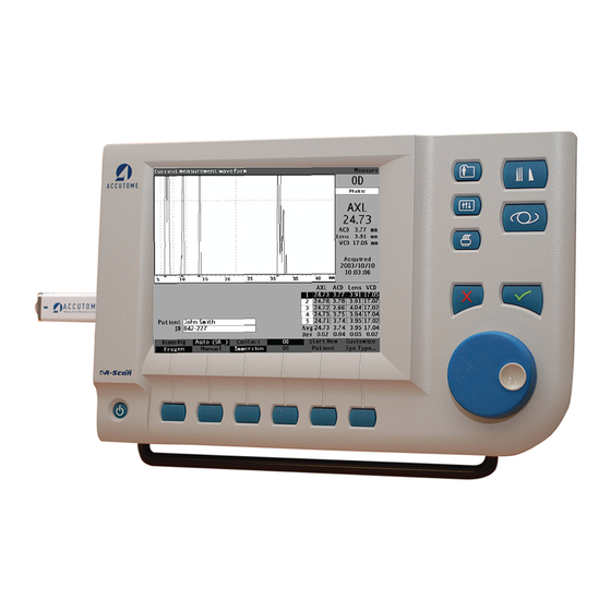
Introduction Introduction Accutome A-Scan Plus Overview The Accutome A-Scan Plus pictured below has all the features that make it easy to obtain extreme accuracy and improved patient outcomes. Figure 1-1 Accutome A-Scan Plus... -
Page 18: Features
Accutome A-Scan Plus User’s Guide Features The Accutome A-scan Plus is designed for easy access to all screens and functions. The advanced User Input Knob provides unsurpassed ease of use and the straightforward Graphical User Interface guides you through every operation. -
Page 19: Iol Calculations
• Highly sensitive 10MHz composite Broadband probe features fixation and multiple mounting options IOL Calculations The Accutome A-Scan Plus is also a leader in IOL Calculations and provides the following: • Modern formulas including Hoffer Q, Holladay, SRK/T, and Haigis •... -
Page 20: Optional Components
Summarizes safety precautions, Safety warnings, symbols, and terms. Section 3 Provides assembly instructions, Getting Started overview of Accutome A-Scan Plus basic operation. Section 4 Describes the interface and how to How to Use the use all the buttons and screens. - Page 21 Networking Section 17 Having read this manual you will be able to assemble the Accutome A-Scan, take measurements, calculate IOL power, customize IOL constants and eye types, and save Patient records.
-
Page 22: Chapter 2: Safety
Federal law restricts this device to sale by or on the order of a physician. Safety Issues to Consider When Using the Accutome A-Scan Plus The Accutome A-Scan Plus is non-invasive. The ultrasonic biometry probe touches the surface of the anesthetized cornea during the scanning process. The probe must be cleaned before and after use. -
Page 23: Symbols Definitions For The Accutome
Safety Symbols Definitions for the Accutome Statements, graphics and symbols listed below are used on components of the Accutome A-Scan Plus. Descriptions and meanings are listed to the right of the symbols. “Attention! Consult instruction manual.” Single phase alternating current When pressed turns the power on and off. -
Page 24: Safety Precautions
User’s Guide Power connector Disposal of Product within EU Safety Precautions There are several areas in the use of the Accutome A-Scan that require special attention, as they may pose a safety threat. Sterilization Sterilization issues are confined to the A-Scan probe that comes in contact with the patient’s eye. In order to prevent the transmission of disease, OSHA and CDC guidelines are referenced for proper control of sterilization issues. -
Page 25: Disinfection And Cleaning
WARNING!! DO NOT IMMERSE THE PROBE’S CABLE OR METAL CONNECTOR. ALLOW TO DRY BEFORE USE. CAUTION: General indications for use of the Accutome probe, include; external, structurally intact areas of the eye globe and orbit areas only. -
Page 26: Electrical Hazard And Safety
Use only hospital-grade power cords and the connectors supplied with the Accutome A-Scan Plus. Also, be sure the power cords and connectors are in good condition. A ground cable can be provided if required; Accutome part number: 24-4045. -
Page 27: Avoiding Electromagnetic And Other Interference
To avoid electromagnetic interference, the device must be installed and put into operation in accordance with the user manual and using the components supplied by Accutome. ALARA Principle When using this instrument, the ALARA (As Low As Reasonable Achievable) principle should be followed. -
Page 28: Chapter 3: Getting Started
The instrument is built with connectors for each component that is part of the Accutome A-Scan Plus environment. There is also a serial port used to transfer data from the Accutome A-Scan Plus to a computer. -
Page 29: Probe
Getting Started Assembling the Accutome A-Scan Plus Probe The probe provided with the Accutome A-Scan is an essential component. No other probes should be used with the instrument. Footswitch The footswitch can be used to capture, review and delete measurements. -
Page 30: Placing The Accutome A-Scan Plus
Quick-Close Kickstand The quick-close kickstand provided with the Accutome A-Scan Plus provides an easy, stable base for the instrument. To open the kickstand pull the kickstand away from the bottom of the instrument. When opening or closing the kickstand it is best to exert a small amount of outward pressure on the inner sides of the kickstand. -
Page 31: Mounting
Assembling the Accutome A-Scan Plus Figure 3-3 Open Kickstand Mounting The Accutome A-Scan Plus is designed to be mounted with many types of hardware. The back of the Accutome has five threaded holes. Four of the holes are AMPS-NEC compatible and will accept any compatible mounting. In the center of the four holes is one larger hole. The larger hole is designed to accept a camera tripod, pedestal, or wall mount. -
Page 32: Connecting The Footswitch
Insert the connector of footswitch cable into the footswitch connector. Connecting the Power There are two components to connect power to the Accutome A-Scan Plus; there is a power supply which regulates the voltage going to the instrument, and there is a grounded power cable which connects from the power supply to an outlet. -
Page 33: Connecting The Ethernet Connection
Getting Started Assembling the Accutome A-Scan Plus Connecting the Ethernet Connection Locate a regular Ethernet cable (not provided with the unit) with RJ45 connectors. Plug one end of the Ethernet connector and the other end to a Ethernet wall outlet or Ethernet hub. -
Page 34: Connecting The Probe
Accutome A-Scan Plus User’s Guide Connecting the Probe The Accutome A-Scan Plus probe connector is located on the right side of the instrument (facing the instrument). To connect the probe: Locate the probe connector, on the side, at the right of the instrument, facing the screen (see Figure 3-5 below.) -
Page 35: Probe Setup
Figure 3-6 Probe Connected Probe Setup The Accutome A-Scan Plus probe is an integral component. There are several options available for probe use. The Accutome A-Scan Plus probe can be used: With an immersion shell Mounted into a Goldman Tonometer... -
Page 36: Accutome Ultrasonic Probe Kit
Figure 3-7 Accutome Ultrasonic Probe Kit (PN 24-4001) Accutome Ultrasonic Probe Kit (PN 24-4001) The Accutome probe is designed to be used with an Immersion Shell. When using an immersion shell ensure that there is a distance of 5 - 14.5 mm between the bottom of the probe and the bottom of the immersion shell, as shown in Figure 3-9 on next page. -
Page 37: Accutome Probe With Goldman Tonometer Adapter
Figure 3-9 Probe Setup with Immersion Shell Accutome Probe with Goldman Tonometer Adapter The Accutome probe is designed to be used with a Goldman Tonometer Adapter. When using the Tonometer Adapter: 1. Slide the adapter over the end of the probe as shown in Figure 3-10 below. -
Page 38: Accutome Probe With Handle Extension
User’s Guide Accutome Probe with Handle Extension The Accutome probe is designed to be used with an handle extension to increase the length of the probe. When using the probe handle extension: 1. Insert the probe into the handle extension as shown in Figure 3-11 below. -
Page 39: Figure 3-12 Probe With Handle Extension And Insertion Tool
Probe Setup Getting Started Figure 3-12 Probe with Handle Extension and Insertion Tool Figure 3-13 Probe with Handle Extension... -
Page 40: Basic Operation
Accutome A-Scan Plus User’s Guide Basic Operation The basic operation of the Accutome A-Scan Plus consists of the following steps: Power on the instrument. Adjust the LCD display contrast. Take five measurements per eye. Calculate the IOL power for desired result. Print or save the Patient Record. -
Page 41: How To Adjust The Contrast
How to Adjust the Contrast When you turn on the Accutome A-Scan Plus you may have to adjust the contrast of the display. The display is an LCD (Liquid Crystal Display) and depending upon the angle from which you are viewing the screen, the images displayed may not be bright enough or may be too bright. -
Page 42: Using The Test Block
User’s Guide Using the Test Block The Accutome A-Scan Plus is equipped with a test block, located at the top, right side (facing the display) of the instrument. Refer to the Figure below for location. The test block is provided as a way to test the basic operation of the instrument and the probe. -
Page 43: Preparation Of Patient For Examination
Getting Started Probe Setup Preparation of Patient for Examination Preparing a patient for an A-Scan exam consists of the following steps: Anesthetizing the patient’s eye with a topical anesthetic such as Proparacaine. Please refer to the manufacturer’s instructions for proper use. 2. -
Page 44: Figure 3-18 Patient Information Field
User’s Guide Press the button under the “Start New Patient” selection on the Measure, Calculate IOL or Patient Records Screens. Refer to Figure 3-18 below. When you start a new patient the Accutome A-Scan Plus will clear all fields on the Measure Screen as follows: •... -
Page 45: Figure 3-19 Patient Information Field Opened
Getting Started Basic Operation Press the enter button, the knob or the check mark to activate the patient information field. Figure 3-19 Patient Information Field Opened The patient’s last name will be highlighted, using the keyboard type in the last name. Figure 3-20 Enter Patient’s Last Name... -
Page 46: Figure 3-21 Enter Patient Information
Accutome A-Scan Plus User’s Guide Press the tab key saves the entry and advances to the next entry in one step. Figure 3-21 Enter Patient Information Type in the patient’s first name Pressing the tab key saves the entry and advances to the next entry in one step. -
Page 47: How To Enter Text Without A Keyboard
The keyboard is optional with the Accutome A-Scan Plus. The keyboard makes entering text very easy. When a field is active requiring text, and you have a keyboard, you simply have to enter the text. The Accutome A-Scan Plus also provides a method of entering text that does not require a keyboard. If a field is activated that requires text, and the keyboard has not been used, the instrument displays a screen keyboard in the soft menu area, shown in Figure 3-22 below, that contains all the alphanumeric characters. -
Page 48: Screen Keyboard Features
If you would like to switch to lower case press the button below “Case”. The Accutome A-Scan Plus automatically selects upper case for a blank field, unless the field has been previously edited in lower case and will then revert to lower case. The Accutome A-Scan Plus allows you to switch between using the optional keyboard and the screen keyboard. To quickly select characters on the screen keyboard turn the data knob quickly to accelerate the selection location. -
Page 49: Entering A Patient With The Screen Keyboard
Basic Operation Getting Started Entering a Patient with the Screen Keyboard To enter the Patient Name with the screen keyboard: Select the Patient field by rotating the knob. Press the knob or the √ button, to open the patient information screen field. Using the knob, select the patient field. Press the knob on √ button to activate the field. The screen keyboard will appear at the bottom of the screen. Rotate the knob to select the first letter, or number of the Patient field. Press the knob or the √ button, to enter the character in the field. Rotate the knob to select the next character. Press the knob or the √ button, to enter the character in the field. -
Page 50: How To Take A Measurement
• Automatic/Manual - which method are you using to take the measurement automatic or manual? Automatic allows the Accutome to determine when the probe has acquired a measurement and manual allows the operator to determine when to capture the waveform. - Page 51 Frozen selection. The Accutome A-Scan Plus will proceed to the next empty waveform (if available). If you are using the Automatic mode, the Accutome A-Scan Plus will automatically freeze a measurement upon sclera detection, steep retina detection or upon capturing stable readings. (Auto Mode settings are defined in the Setup Screen.) The instrument will emit a high pitched chirp when you have...
-
Page 52: How To Perform A Calculation
Accutome A-Scan Plus User’s Guide How to Perform a Calculation After you have completed a Patient’s scans you can calculate the power of the IOL for the Patient. You can perform the calculation from the Calculate IOL Screen. To calculate a lens:... -
Page 53: Figure 3-25 Calculate Iol Screen
Getting Started Basic Operation 2. The Accutome will display the Calculate IOL Screen as shown in Figure 3-25 below Note: For more information on Calculating IOLs refer to the “Performing Calculations” section of this manual. Select the IOL Group, if necessary, by pressing the button beneath the selection “Select IOL Group”... -
Page 54: Figure 3-26 Acd Field Selected
ACD value in millimeters (mm). If you would like the Accutome to calculate the phakic ACD press the “Delete” key or the X button to remove the entered value and replace it with “Calc” for a calculated value. -
Page 55: Figure 3-27 K1, K2 Values
Enter K2 value in the same manner as K1. Note: When you first receive the Accutome A-Scan Plus the IOL Groups are empty. If there are no IOL Groups present on the Calculate IOL Screen you will not be able to perform a calculation. Refer to the “Setting Up IOL Groups” section for further information. -
Page 56: Figure 3-28 Calculation Completed
These values are the optimal lens, and do not necessarily exist in the real world. The Accutome A-Scan Plus also provides you with the power of the IOL that would achieve emmetropia. The emmetropic power is calculated and displayed under the ametropoic power in a smaller font. -
Page 57: How To Print A Records
2. The Accutome A-Scan Plus will print the calculation record. How to Save Patient Records The Accutome A-Scan Plus allows you to save patient records at any time to either internal memory, USB stick or network drive.You can save the record after you have taken all the desired measurements or, after you have taken the measurements and performed the calculation. -
Page 58: Figure 3-29 Patient Record Storage
User’s Guide Figure 3-29 Patient Record Storage Press the button below “Save to List”. The Accutome A-Scan Plus will store the Patient record. The “Not Saved” prompt Patient ID will be changed to “Saved” and a new entry will appear in the Patient List. -
Page 59: Chapter 4: How To Use The Buttons And Screens
There is also a large knob with an indented push-button area located to the right of the screen, below the dedicated function buttons. The knob is the central component of the Accutome A-Scan Plus user interface. The knob allows you to select and change fields on every instrument screen. -
Page 60: Accutome A-Scan Plus Buttons
Navigation Controls Figure 4-1 Accutome A-Scan Plus Buttons Accutome A-Scan Plus Buttons There are two types of buttons available on the Accutome A-Scan Plus front panel, dedicated buttons and soft menu buttons. Dedicated Buttons The dedicated buttons, located at the side of the front panel, in the same area as the knob, all perform a dedicated function. -
Page 61: Measure Button
From the Calculate Screen you can also access the IOL Groups Screen. If you press the Calculate button multiple times the Accutome will scroll and display the lower level logically linked screens; i.e. IOL Groups Screen and Personalize IOLs Screen. -
Page 62: Print
Press on the Negative button to cancel deleting the record. Soft Menu Buttons There is a series of buttons directly below the Accutome display. The buttons offer soft menu selections and change from screen to screen. There are three types of soft menu selection: •... -
Page 63: Buttons That Toggle Between Two Selections
Screens The Accutome A-Scan Plus is set up as a series of high level screens with logically linked lower level screens. Each of the high level screens is accessed by pressing one of the dedicated function buttons. -
Page 64: What The Screen Displays
Tips One of the features that makes the Accutome A-Scan Plus so intuitive to use is the tips available on every screen. The tips are displayed at the top left of each screen. The message displayed describes the currently selected screen element. -
Page 65: Error Messages
A confirmation beep sounds after a patient is saved and after a patient is recalled. Error Messages There are certain situations where the Accutome A-Scan Plus will provide an error message, as well as the tones indicating error. Error messages will be displayed when there is a problem with printing or any condition that requires user attention. -
Page 66: High Level Screen Buttons
• Patient Records - for saving, retrieving, deleting and batch printing patient records • Preferences - for defining eye types, velocities and Accutome settings Associated Sub-Level Screens Each of the high level screens has associated lower level screens that are accessed by pressing a soft menu button on the high level screen. -
Page 67: From The Patient Records Screen
Button and Screens Screens From the Patient Records Screen There is are four lower level screens available from the Patient Records Screen. They include save/recall, print, delete and transfer. From the Preferences Screen From the top level of the Preferences Screen, which is Eye Types, you can access the Setup Screen. -
Page 68: Active Area
The active area on any screen is surrounded by a dashed border. Text Entry Certain screens require text entry. The Accutome A-Scan Plus will automatically provide you with a new soft menu of alphanumeric characters. You select the various characters by rotating the knob and enter the characters into the text field by pressing on the knob or the Affirmative button. -
Page 69: Fields Requiring Information
3. When the field is active, rotate the knob until you reach the appropriate value. Keyboard Shortcuts The Accutome A-Scan Plus allows you to perform operations from the keyboard. There is no need to push buttons to acquire patient measurements; all measurement functions can be executed using the keyborad shortcuts given in... - Page 70 Accutome A-Scan Plus User’s Guide Table 4-1 Keyboard Shortcuts Action F1 - F6 Correlate to the soft menu keys, functions change according to selected screen Same as Print key Operates like the footswitch, will display the Measure Screen from other screens,...
-
Page 71: Using The Footswitch
Keyboard Shortcuts Button and Screens Select Threshold Gate Select Zoom (press and hold for default) Select Scroll (press and hold for default) Select View 1,2,3,4 Select waveform Using the Footswitch The footswitch performs four functions: When you are acquiring measurements, the footswitch will capture a waveform. 2. -
Page 72: Setting Up The Accutome A-Scan Plus
Preferences Setting Up the Accutome A-Scan Plus The Accutome A-Scan Plus is equipped with personal preference options, and provides the flexibility necessary to customize your machine. You can not only add eye types and lens materials, but you can also set many operational defaults. -
Page 73: How To Access Preferences
(see Figure 5-1 below). Preferences Button Figure 5-1 Preferences Button Note: If you press the Preferences button a second time the Accutome A-Scan Plus will scroll to the Setup Screen, which is the next lower level linked screen. -
Page 74: Top Level Of Preferences
User’s Guide Top Level of Preferences When you press the Preferences button the Accutome A-Scan Plus will display the Eye Types screen (see Figure 5-2 below). In the Eye Types screen you can add a new Eye Type, new lens material, new Anterior/Vitreous material and assign velocities to each of these materials. -
Page 75: How To Add A New Eye Type
Lens Material and Velocity, and new Anterior/Vitreous Material and Velocity. Note: It is also possible to edit existing Eye Type information in the Accutome A-Scan Plus. To edit eye type information follow the same procedure as adding eye type information. -
Page 76: Adding A New Lens Material
Accutome A-Scan Plus User’s Guide Adding a New Lens Material Before using a material in the definition of an Eye Type, the lens material must exist in the lens material table. To add a new lens material: Rotate the knob and select the Lens Material table. The table is selected when it is surrounded by a solid black border. -
Page 77: Figure 5-4 Selecting A Cell To Enter New Lens Material
How to Add a New Eye Type Preferences Press the knob to activate the Lens Material table. The table is activated when it is surrounded by a dashed border as shown in Figure 5-4 below. When the table is activated rotate the knob until an empty cell in the Material column is selected. -
Page 78: Assigning A Velocity To The New Lens Material
Figure 5-5 Entering the Name for New Lens Material Assigning a Velocity to the New Lens Material The Accutome A-Scan Plus is set up at the factory with default sonic velocities for the most common types of lens materials. The Accutome A-Scan Plus knows which velocity to use for each eye type. -
Page 79: Adding The New Eye Type Information
How to Add a New Eye Type Preferences Figure 5-6 Adding New Material Velocity Adding the New Eye Type Information Rotate the knob and select the Eye Types table. Press the knob or the √ button, to activate the Eye Types table. Within the Eye Types table, rotate the knob to select an empty cell, indicated by a solid black border, for entering the new eye type name. -
Page 80: Figure 5-7 Selecting The Eye Type Name Cell
Accutome A-Scan Plus User’s Guide Figure 5-7 Selecting the Eye Type Name Cell Enter the name of the new Eye Type. Press the knob or the √ button, to save the Eye Type Name and to deactivate the cell. Figure 5-8 Adding the New Eye Type Name... -
Page 81: Figure 5-9 Activating The Area To Select New Lens Material
How to Add a New Eye Type Preferences Within the Eye Types table, rotate the knob to select the Lens cell associated with the Eye Type Name you just entered. Press the knob or the √ button, to activate the cell, indicated by the dashed border. -
Page 82: Figure 5-10 Lens Material Selected
Accutome A-Scan Plus User’s Guide Figure 5-10 Lens Material Selected Within the Eye Types table, rotate the knob to select the Lens Thickness Cell associated with the current Eye Type Name, and Lens. Press the knob or the √ button, to activate the cell, indicated by the dashed border. -
Page 83: Figure 5-11 Lens Thickness Entered
Preferences How to Add a New Eye Type Figure 5-11 Lens Thickness Entered Within the Eye Types table, rotate the knob to select the AC cell associated with the current Eye Type Name, and Lens. Press the knob or the √ button, to activate the cell, indicated by the dashed border. -
Page 84: Figure 5-12 Anterior Chamber Material Selected
Accutome A-Scan Plus User’s Guide Figure 5-12 Anterior Chamber Material Selected Within the Eye Types table, rotate the knob to select the VC cell associated with the current Eye Type Name, Lens, and Anterior Chamber. Press the knob or the √ button, to activate the cell, indicated by the dashed border. -
Page 85: Eye Type Screen Menu Selections
How to Add a New Eye Type Preferences Figure 5-13 Vitreous Chamber Material Selected Eye Type Screen Menu Selections There are three menu selections available for execution at the bottom of the Eye Types Screen. Two of the selections, “Reset Field to Factory” and “Reset All to Factory”... -
Page 86: Figure 5-14 Non-Factory Field
Figure 5-14 Non-Factory Field Press the button beneath the “Reset Field to Factory” selection. The Accutome A-Scan Plus will prompt you with the message “Are you sure?” as shown in Figure 5-15 on the next page. You must select either “Cancel”... -
Page 87: Figure 5-15 Restore Selected Field Prompt
Preferences How to Add a New Eye Type Figure 5-15 Restore Selected Field Prompt The Accutome A-Scan Plus will reset the selected field to its factory default as shown in Figure 5-16 on the next page. -
Page 88: Reset All To Factory
Accutome A-Scan Plus User’s Guide Figure 5-16 Selected Field Restored Reset All to Factory The Reset All to Factory selection provides you with the ability to return all pre-entered fields on the Eye Types Screen to their default factory values. -
Page 89: Figure 5-17 Non-Factory Fields Displayed
Eye Type Screen Menu Selections Preferences Figure 5-17 Non-Factory Fields Displayed The Accutome A-Scan Plus will prompt you with the message “Are you sure?” as shown in Figure 5-18 on the next page. You must either cancel or continue. Press the button beneath the selection “Yes”. (You can also press the Affirmative button located towards the right side of the front panel.) -
Page 90: More Settings
From the high level Eye Types Screen you can access the remainder of the preference options. When you press the button beneath the selection “More Settings” the Accutome A-Scan Plus will display the Setup Screen as shown in Figure 5-19 on the next page. -
Page 91: Setup Screen Soft Menu
Preferences More Settings • Default K Index • IOL Step for IOL Calculation Power Table • Network folder • Date • Time • Auto Mode Setup Screen Soft Menu The Setup screen has the following soft menu selections activated by the buttons beneath the selection: •... -
Page 92: How To Set The Printer
User’s Guide How to Set the Printer In order to obtain the best print out possible from the Accutome A-Scan Plus, it is recommended that all records be printed to a HP, or HP compatible printer. The Accutome A-scan plus has over 200 HP drivers included in the software. -
Page 93: Figure 5-21 Printer Field Open
Preferences More Settings Press the knob or the √ button, to activate the field, indicated by the dashed border as shown in 5-21. Figure 5-21 Printer Field Open... -
Page 94: Figure 5-22 Selecting The Printer
Accutome A-Scan Plus User’s Guide Within the Printer field, rotate the knob to select one of the pre-entered options as shown in 5-22. Figure 5-22 Selecting the Printer... -
Page 95: Figure 5-23 Printer Selected
Press the knob or the √ button, to save the selected Printer and to deactivate the field as shown in figure 5-23. Figure 5-23 Printer Selected The Accutome A-Scan has the ability to update the printer driver as new releases become available from Accutome. To Update printer drivers:... -
Page 96: Figure 5-24 Select Printer
Accutome A-Scan Plus User’s Guide Within the setup screen, rotate the knob and select printer, indicated by the solid black border as shown in figure 5-24. Figure 5-24 Select Printer... -
Page 97: Figure 5-25 Activate The Printer Field
Preferences More Settings Press the knob or the check mark, to activate the printer field, indicated by the dashed border as shown in firgure 5-25. Figure 5-25 Activate the Printer Field... -
Page 98: Figure 5-26 Printer Selection "None
Accutome A-Scan Plus User’s Guide Rotate the knob until “none” is selected as shown in figure 5-26. Figure 5-26 Printer Selection “None”... -
Page 99: Figure 5-27 New Patient Selected
Preferences More Settings Press the knob or the check mark to confirm selection of none as shown in firgure 5-27. Figure 5-27 New Patient Selected... -
Page 100: Figure 5-28 Update Selected
Accutome A-Scan Plus User’s Guide Within the setup screen, rotate the knob to select “Update...” field, indicated by a solid black border. Figure 5-28 Update Selected... -
Page 101: Figure 5-29 Are You Sure
Preferences More Settings Press the knob or the check mark button, to activate the field, indicated by the dashed border as shown in figure 5-29. Figure 5-29 Are You Sure? The screen will prompt: “Are you sure? Update Custom printer drivers from USB Disk?”... -
Page 102: Figure 5-30 Driver Update Complete
Accutome A-Scan Plus User’s Guide Upon completion of the updating of the files, the system will prompt you, “Driver update complete.” Press OK as shown in figure 5-30. Figure 5-30 Driver Update Complete... -
Page 103: Figure 5-31 Select Printer Field
Preferences More Settings Within the set up screen, rotate the knob and select printer, indicated by the solid black border as shown in figure 5-31. Figure 5-31 Select Printer Field... -
Page 104: Figure 5-32 Selecting Custom Print Drives
Accutome A-Scan Plus User’s Guide Press the knob or the check mark, to activate the printer field, indicated by the dashed border as shown in figure 5-32. Figure 5-32 Selecting Custom Print Drives Rotate the knob until “custom” is selected. -
Page 105: How To Set The Print Title
Figure 5-33 Custom Print Drivers Selected How to Set the Print Title The Accutome A-Scan Plus provides you with the ability to have a title appear on every patient printout. For example, you may want to have a clinic name... -
Page 106: Figure 5-34 Print Title Field Selected
Accutome A-Scan Plus User’s Guide To set a Print Title: Within the Setup Screen, rotate the knob to select the Print Title field, indicated by a solid black border as shown in figure 5-34. Figure 5-34 Print Title Field Selected... -
Page 107: Figure 5-35 Print Title Field Activated
Preferences More Settings Press the knob or the √ button, to activate the field, indicated by the dashed border as shown in figure 5-35. Figure 5-35 Print Title Field Activated... -
Page 108: Figure 5-36 Entering The Print Title
Accutome A-Scan Plus User’s Guide Within the Print Title field, enter the title you would like printed on every record as shown in figure 3-36. Figure 5-36 Entering the Print Title... -
Page 109: How To Select Automatic Or Manual Network Address
Preferences More Settings Press the knob or the √ button, to save the entered Print Title and to deactivate the field as shown in figure 5-37. Figure 5-37 Print Title Added How to Select Automatic or Manual Network Address The network address allows you to receive the IP address automatically or enter static address manually. -
Page 110: Figure 5-38 Selecting Automatic Network Address
Accutome A-Scan Plus User’s Guide Press the knob or check mark to confirm the selection. Figure 5-38 Selecting Automatic Network Address... - Page 111 Preferences More Settings When set to manual, please refer to the site’s network manager for the following information: Static IP address, Subnet mask, and Gateway address. The following steps will guide you through entering data in “Manual” mode: Press “Enter” or “√” button to activate the box to allow changes.
-
Page 112: How To Adjust The Contrast
The contrast can be adjusted at any time, on any screen, by pressing and holding the preferences button while turning the knob. To adjust the Accutome A-Scan Plus Contrast: Within the Setup Screen, rotate the knob to select the Contrast field, indicated... -
Page 113: Figure 5-39 Contrast Field Selected
Preferences More Settings Figure 5-39 Contrast Field Selected Press the knob or the √ button, to activate the field, indicated by the dashed border as shown in figure 5-40. -
Page 114: Figure 5-40 Contrast Field Activated
Accutome A-Scan Plus User’s Guide Figure 5-40 Contrast Field Activated... -
Page 115: Figure 5-41 Adjusting The Contrast
Preferences More Settings With the Contrast field active, rotate the knob to adjust the white/grey contrast of the screen. The amount of grey vs. white is indicated in the Contrast field by a solid grey bar, that increases or decreases as you adjust the contrast as shown in figure 5-41. -
Page 116: How To Set The Default Patient Eye Type
How to Set the Default Patient Eye Type The Accutome A-Scan Plus has a default eye type setting so that every time you start a new patient you do not have to select an eye type. When you start a new patient the eye type displayed on the Measure Screen will be the default eye type selected in the Setup Screen. -
Page 117: Figure 5-43 Default Eye Type Field Selected
Preferences More Settings Figure 5-43 Default Eye Type Field Selected Press the knob or the √ button, to activate the field, indicated by the dashed border as shown in figure 5-44. Figure 5-44 Default Eye Type Field Activated... -
Page 118: Figure 5-45 New Default Eye Type Selected
Accutome A-Scan Plus User’s Guide Within the Default Eye Type field, rotate the knob to select one of the pre-entered Eye Types as shown in Figure 5-45 below Figure 5-45 New Default Eye Type Selected Press the knob or the √ button, to save the selected Default Eye Type and... -
Page 119: How To Set The Default Id
Figure 5-46 Default Eye Type Changed How to Set the Default ID The Accutome A-Scan Plus provides you with the ability to have a Default ID appear whenever you start a new patient. For example, you may want to have a doctor’s name, or a clinic’s name as a Default ID. - Page 120 Accutome A-Scan Plus User’s Guide Figure 5-47 Default ID Field Selected Press the knob or the √ button, to activate the field, indicated by the dashed border as shown in figure 5-48.
-
Page 121: Figure 5-48 Default Id Field Activated
Preferences More Settings Figure 5-48 Default ID Field Activated Within the Default ID field, enter the default ID as shown in figure 5-49. Figure 5-49 Entering the Default ID... -
Page 122: How To Set The Default Gain
Accutome A-Scan Plus User’s Guide Press the knob or the √ button, to save the entered Default ID and to deactivate the field as shown in figure 5-50. Figure 5-50 Default ID Added How to Set the Default Gain The Default Gain parameter allows you to adjust the new patient ultrasound gain. -
Page 123: Figure 5-51 Default Gain Field Selected
Preferences More Settings Figure 5-51 Default Gain Field Selected Rotate the knob to select one of the pre-entered gain values, or manually enter the new value. The gain is adjustable in increments of 1 dB from 0- 23 dB. When the gain is at the appropriate level, press either the knob or the √ button, to save the adjusted value and to deactivate the field as shown in figure 5-52. -
Page 124: How To Set The Target Refraction
When you are calculating IOLs, one of the values you need to enter is the desired target refraction. The Accutome A-Scan Plus allows you to specify the default target refraction that is most common for patients. It is also possible to modify the target refraction on a per patient basis. -
Page 125: Figure 5-53 Target Field Selected
Preferences More Settings Figure 5-53 Target Field Selected Press the knob or the √ button, to activate the field, indicated by the dashed border as shown in figure 5-54. Figure 5-54 Target Field Activated... -
Page 126: Figure 5-55 Adjusting The Target
Accutome A-Scan Plus User’s Guide With the Target field active, rotate the knob until you reach the appropriate value or enter the target number on the keyboard as shown in figure 5-55. Figure 5-55 Adjusting the Target Press the knob or the √ button, to save the entered Default ID and to... -
Page 127: How To Set The K Index
Setup screen default K Index, a * appears beside the entry. To change or view the K index, change or reenter the diopter entry. The Accutome A-Scan Plus will prompt you with the default and current K indexes and ask which one... -
Page 128: Figure 5-57 K Index Field Selected
Accutome A-Scan Plus User’s Guide To set the K index: Within the Setup Screen, rotate the knob to select the K Index field, indicated by a solid black border as shown in figure 5-57. Figure 5-57 K Index Field Selected Press the knob or the √... -
Page 129: Figure 5-58 K Index Field Activated
Preferences More Settings Figure 5-58 K Index Field Activated Rotate the knob to adjust the K index , or manually enter the new value. The maximum value is 1.5000 and the minimum is 1.2500 as shown in figure 5-59. Figure 5-59 Adjusting the K Index... -
Page 130: How To Set The Iol Step
5-60. Figure 5-60 K Index Field Adjusted How to Set the IOL Step The Accutome A-Scan Plus allows you to modify the diopter step used when calculating IOL power. To adjust the IOL Step: Within the Setup Screen, rotate the knob to select the IOL Step field, indicated by a solid black border as shown in figure 5-61. -
Page 131: Figure 5-61 Iol Step Field Selected
Preferences More Settings Figure 5-61 IOL Step Field Selected Press the knob or the √ button, to activate the field, indicated by the dashed border as shown in figure 5-62. Figure 5-62 IOL Step Field Activated... -
Page 132: Figure 5-63 Adjusting The Iol Step
Accutome A-Scan Plus User’s Guide Rotate the knob to select one of the pre-entered step values, or manually enter the new value. The IOL power step is adjustable in increments of 0.05 D from 0.05 - 5.00 D as shown in figure 5-63. -
Page 133: Figure 5-64 Iol Step Adjusted
Preferences More Settings Figure 5-64 IOL Step Adjusted... -
Page 134: How To Activate The Network Folder
Accutome A-Scan Plus User’s Guide How to Activate the Network Folder Within the set up screen, rotate the knob to select the Network folder on/ off field, indicated by a solid black border as shown in figure 5-65. Figure 5-65 Selecting Network Folder On/Off Press the knob or the check mark, to activate the field, indicated by the dashed border. -
Page 135: Configure Network Folder
Preferences More Settings Configure Network Folder: Move the selection to the “Network Folder” section. The first entry is the “On/Off” toggle. The default is “On”. In case networking is not available or users do not intend to use the networking features, it can be turned to “Off”. - Page 136 Accutome A-Scan Plus User’s Guide Set up an account and share a folder from a windows PC and collect the follwoing information. The following are required fields: • Computer name (Host). • Shared folder name (Folder). • User name of an account on the PC (User).
- Page 137 Preferences More Settings Type in the computer name and press “Enter” when fin- ished. The border of the box will turn to a dashed line when you start typing and turn back to solid after you press “Enter”. Press “Tab” key to move to the “Folder”...
- Page 138 “Enter” again and it will activate the entire box and use the “Tab” key to move up and down. Note: The A-Scan Plus won’t start making any connection until we press the “Done” button. Please follow the next section for making and testing connections.
-
Page 139: Testing Network Connection On The A-Scan Plus
More Settings Testing Network Connection on the A-Scan Plus After we configure the network folder connection on the A-Scan Plus, we can start testing the connection. Make sure the network and the PC are up and run- ning before we can start testing the connection. -
Page 140: How To Adjust The Date And Time
The Measure Screen displays the date and time that a waveform is captured. When you first set up the Accutome A-Scan Plus you can adjust the date and time as appropriate for your time zone. Both the date and time are divided into three separate fields. -
Page 141: Figure 5-68 Day Field Activated
More Settings Preferences Press the knob or the √ button, to activate the field, indicated by the dashed border as shown in figure 5-68. Figure 5-68 Day Field Activated... -
Page 142: Figure 5-69 Adjusting The Day
Accutome A-Scan Plus User’s Guide With the Day field active, rotate the knob until you reach the appropriate day number or enter the number with the keyboard as shown in figure 5-69. Figure 5-69 Adjusting the Day Press the knob or the √ button, to save the adjusted Day and to deactivate... -
Page 143: How To Set The Auto Mode
How to Set the Auto Mode The Accutome A-Scan Plus allows you to define the Automatic measurement mode by specifying how a measurement is automatically captured. There are a total of three criteria available and each can be turned off or on by the user on the Setup screen. - Page 144 Accutome A-Scan Plus User’s Guide The Auto Mode setting is displayed in the soft menu on the Measure Screen as ‘Auto (SRS), where (SRS) means Sclera, Retina, Stable. If the feature is ON, the first letter appears in its place, otherwise a placeholder ‘_’ is displayed.
-
Page 145: Figure 5-71 Auto Mode Sclera Selected
Preferences More Settings Figure 5-71 Auto Mode Sclera Selected Press the knob or the √ button, to activate the field, indicated by the dashed border as shown in figure 5-72. Figure 5-72 Auto Mode Sclera Field Activated... -
Page 146: Figure 5-73 Changing The Auto Mode - Turning On Sclera
Accutome A-Scan Plus User’s Guide With the Sclera field active, rotate the knob until you the word “On” is displayed. Automatic mode will no longer be triggered by sclera detection as shown in figure 5-73. Figure 5-73 Changing the Auto Mode - Turning On Sclera Press the knob or the √... -
Page 147: Figure 5-74 Auto Mode - "Sclera" On
Preferences More Settings Figure 5-74 Auto Mode - “Sclera” On If you would like to define the Auto Mode by Retina signal quality, rotate the knob to select the “Retina” field. 2. Press the knob or the √ button, to activate the field, indicated by the dashed border. -
Page 148: Figure 5-75 Auto Mode - "Stable" Selected
Accutome A-Scan Plus User’s Guide Figure 5-75 Auto Mode - “Stable” Selected Press the knob or the √ button, to save Stable as On and to deactivate the field. Figure 5-76 Auto Mode Defined by “Stable” Measurement... -
Page 149: Sound On/Sound Off
The screen saver feature is provided to protect the LCD from unnecessary wear. If the screen saver is enabled and the Accutome A-Scan Plus is unused for 30 minutes, the instrument will display the screen saver and the display will go dark. -
Page 150: Save And Restore Factory Default Gates And Threshold
User’s Guide Save and Restore Factory Default Gates and Threshold You may find, after using the Accutome A-Scan Plus for a while, that you frequently have to adjust one or several gates and threshold. If you continually make the same adjustments to gates/threshold, you may want to save the adjusted settings as the default for gates/threshold. -
Page 151: Figure 5-77 About This Unit Screen
Preferences More Settings Figure 5-77 About This Unit Screen Note: If setup is complete, press the button beneath the selection “Done” and you will return to the Eye Types Screen. -
Page 152: Overview
Performing Measurements Overview The Accutome A-Scan Plus is very simple to operate, and has advanced features to help you obtain the best possible measurements. The Accutome A-Scan Plus takes measurements by sending a signal through the eye through the ultrasonic probe. The signal echoes off the various parts of the eye (cornea, lens, retina) and returns a signal through the probe. -
Page 153: Measure Screen
Capture mode (automatic or manual), and probe coupling method (contact or immersion) remain as last set by the user and are retained while the Accutome A-Scan Plus is turned off. Figure 6-1 Measure Screen Displaying Current Settings... -
Page 154: Information Displayed On The Measure Screen
Accutome A-Scan Plus User’s Guide Information Displayed on the Measure Screen The Measure Screen provides the continuous display of Axial Length, ACD, Lens Thickness, and Vitreous dimensions for the active patient. The top, left side of the screen displays the active patient waveform. Within the waveform display are time gates and amplitude threshold to control the capture and measurement of the waveforms. -
Page 155: Starting A New Patient
How to Set the Eye Type When the Accutome A-Scan Plus is set up at the factory, it is equipped with predefined eye types and specific velocities for the predefined eye types. Descriptions of the factory installed eye types and their characteristics are given below, followed by instructions on modifying eye types on a per patient basis. -
Page 156: Eye Type Materials And Velocities
Accutome A-Scan Plus User’s Guide Note: All eye types, including Aphakic, have an assumed cornea of 0.55 mm at a velocity of 1641 m/sec. This assumption is included in the ACD measurement. Eye Type Materials and Velocities The tables below list the preset eye types and define the materials and velocities for each eye type. -
Page 157: Setting The Eye Type
Setting the Eye Type The patient’s OD or OS eye type may not match the default provided by the Accutome A-Scan Plus default preferences. To set the eye type: 1. Within the Measurement Screen, rotate the knob to select the eye type located at the top right side of the screen. -
Page 158: Figure 6-3 Eye Type Active
Accutome A-Scan Plus User’s Guide Press the knob or the √ button, to activate the field, indicated by the dashed border. (See Figure 6-3 below.). Figure 6-3 Eye Type Active Within the eye type field, rotate the knob to scroll through the list of eye types. -
Page 159: Probe Application Methods
Select the method you will be using by pressing the Contact/Immersion soft menu button. Immersion The Accutome A-Scan Plus makes it easy to use the Immersion method. The immersion method yields improved accuracy by allowing direct detection of the corneal echo and eliminating compression of the ACD associated with the contact method. -
Page 160: Contact
Auto Mode When you are using the Auto mode, the Accutome A-Scan Plus uses the definition of automatic measurement that has been set up in the unit’s preferences. The user is allowed to define the Automatic measurement mode by specifying how a measurement is automatically captured. -
Page 161: Manual Mode
For more information on setting the Auto mode refer to the “How to Set the Auto Mode” section of this manual. Another aspect of the Auto Mode that is established in the Accutome A-Scan Plus setup is the Restart feature. If ’Restart’ is set to ’ON’ and less than five measurements have been taken, the Auto mode restarts measurement after automatic capture. -
Page 162: Using The Measure Button
Using the Measure Button When you want to capture a waveform, press the Measure button at the top right corner. The Accutome A-Scan Plus will switch from Running to Frozen. How to Select a Measurement After you have taken measurements you may want to go back and review one of the captured waveforms. -
Page 163: Selecting A Measurement Using Waveform Review Menu
Performing Measurements How to Capture a Waveform Figure 6-5 Measurement Selected Selecting a Measurement Using Waveform Review Menu The Waveform Review Menu will be displayed at the bottom of the Measure Screen when the waveform area is active. To select a measurement using the Waveform Review Menu: 1. -
Page 164: Selecting A Measurement With The Footswitch
Accutome A-Scan Plus User’s Guide Figure 6-6 Measurement Activated with Waveform Review Menu Press the button beneath the “View” selection. The measurement outlined with white text against a black background in the Measurement Table is the active measurement. The View button will scroll through all the measurements in the Measurement Table. -
Page 165: How To Delete A Measurement
You can use DELETE on the keyboard to delete the active measurement. How to Adjust Gates/Threshold The Accutome A-Scan Plus takes measurements by sending a signal through the eye via the ultrasonic probe. The various parts of the eye have different velocities. -
Page 166: Available Gates/Threshold
Accuracy depends upon the location of the gates and threshold along the waveform. The purpose of the gates/threshold is to delimit events. The gates/threshold tell the Accutome A-Scan Plus when to start looking for the different events in the waveform. Events will be detected to the right of the gate and above the threshold. -
Page 167: Selecting Gates/Threshold
Press the knob or the √ button, to activate the current waveform area, indicated by the dashed border as shown in figure 6-8. When the current waveform is active, the Accutome A-Scan Plus will display a new soft menu at the bottom of the Measure screen. -
Page 168: Waveform Review Menu
Accutome A-Scan Plus User’s Guide Waveform Review Menu The Waveform Review menu has selections for adjusting gates/threshold, gain, zoom, scrolling, selecting a waveform and for exiting the menu. To select an item from the menu for adjustment, press the button beneath the selection and then rotate the knob to make the adjustment. -
Page 169: How To Adjust The Anterior Lens Gate
Performing Measurements How to Adjust Gates/Threshold Tip: You can use C to select the Cornea Gate directly from the keyboard, or hold to select cornea gates for all measurements. Rotate the knob to move the cornea gate close to the cornea echo. When the gate is in the proper position, either press the button beneath the gate selections to select another gate for adjustment or press the button beneath “Done”, the knob or the √... -
Page 170: Figure 6-10 Anterior Lens Gate Selected
Accutome A-Scan Plus User’s Guide To adjust the anterior lens gate: 1. Press the button beneath the Gate selections until the “Gate Ant Lens” is visible. Tip: You can use A to select the Anterior Lens Gate directly from the keyboard, or hold to select Anterior lens gates for all measurements. -
Page 171: How To Adjust The Posterior Lens Gate
Performing Measurements How to Adjust Gates/Threshold How to Adjust the Posterior Lens Gate The posterior lens gate should be located before the start of the last lens echo. Note: The Posterior Lens Gate is visible only if the eye type requires the lens thickness to be Measured and not assumed. -
Page 172: How To Adjust The Retina Gate
Accutome A-Scan Plus User’s Guide Figure 6-11 Posterior Lens Gate Selected How to Adjust the Retina Gate The retina gate should be located before the start of the retina echo. To adjust the retina gate: Press the button beneath the Gate selections until the “Gate Retina” is visible. -
Page 173: Figure 6-12 Retina Gate Selected
Performing Measurements How to Adjust Gates/Threshold Figure 6-12 Retina Gate Selected The threshold gate should be located at the minimum echo height or amplitude. To adjust the threshold gate: Press the button beneath the Gate selections until the “Gate Threshold” is visible. Tip: You can use T to select the Threshold Gate directly from the keyboard, or hold to select threshold gates for all measurements. -
Page 174: How To Apply Gate Adjustments To All Wavefor
Accutome A-Scan Plus User’s Guide Figure 6-13 Threshold Gate Selected How to Apply Gate Adjustments to All Waveforms You may want to apply a gate adjustment to all current eye waveforms. To apply a gate adjustment: 1. Press and hold the button beneath the Gate selections for approximately one second. -
Page 175: How To Adjust The Gain
Performing Measurements How to Adjust the Gain Move the gate to the desired location. The gate is moved in all waveforms for the current eye. For each movement, each waveform is re-evaluated and new measurements are updated in the measurement table. How to Adjust the Gain The Gain parameter on the Measure Screen allows you to adjust the gain of the signal received from the ultrasonic probe that is displayed as the waveform. -
Page 176: Figure 6-15 Gain Field Changed
Accutome A-Scan Plus User’s Guide Rotate the knob to select one of the pre-entered gain values. Note: To return the gain to the new patient default value, press and hold the gain button for approximately 2 second. Tip: You can use G to increase the gain 1dB directly from the keyboard, or hold to set the gain to the default. -
Page 177: How To Use Zoom
Performing Measurements How to Adjust the Gain How to Use Zoom The zoom feature allows you to zoom in on a selected waveform. The height of the waveform remains the same, only the width changes. Zoom expands the distance scale. The waveform must be selected and active to display the waveform Review menu. -
Page 178: How To Scroll
Accutome A-Scan Plus User’s Guide Tip: You can use CTRL+Z to increase the zoom with wrap directly from the keyboard, or hold to set the zoom to the default 1.6X. Figure 6-17 Zoom Changed How to Scroll The Scroll feature moves the active waveform from left to right and from right to left. -
Page 179: Figure 6-18 Scroll Selected
Performing Measurements How to Scroll Figure 6-18 Scroll Selected Rotate the knob to move the waveform. Tip: You can use CTRL+ S to scroll the waveform increasing 1mm directly from the keyboard, or hold to set the scroll to 0. When the waveform is in the correct position, either press another waveform menu selection or press the button beneath “Done”, the knob or the √... -
Page 180: Switching Eyes
Figure 6-19 Measurement Scrolling Changed Switching Eyes It is very simple to switch between eyes using the Accutome A-Scan Plus. To switch from OD to OS, or from OS to OD press the button beneath the selection OD/OS. The waveforms and eye type for the selected eye will be displayed. -
Page 181: Overview
Customizing Eye Types Overview The Accutome A-Scan Plus not only allows you to create and store custom eye types, you can also customize eye types on-the-fly for an individual patient. Patient Customization If you have a patient with a unique situation, you can specify the eye type, materials, and velocities for either the OD or OS while performing live measurements. -
Page 182: Customize Eye Type Screen
User’s Guide Customize Eye Type Screen The Accutome A-Scan Plus provides access to the Customize Eye Type screen through the Measure screen. When you power on the instrument it starts up at the Measure screen. When you press the button beneath the selection “Customize Eye Type”... -
Page 183: How To Customize An Eye Type
Customizing Eye Types Customize Eye Type Screen • Edit Text - allows you to enter your own field names; you don’t have to select pre-entered values. • Done... - exits the Customize Eye Type Screen and returns you to the Measure Screen. -
Page 184: Figure 7-2 Os Materials Table Selected
Accutome A-Scan Plus User’s Guide Within the Custom Eye Type Screen, rotate the knob to select the Material/Velocity table, indicated by a solid black border. There are two material/velocity tables on the screen. You should select the one to the right of the patient’s eye that you are customizing. -
Page 185: Figure 7-3 Os Materials Table Activated
Customizing Eye Types Customize Eye Type Screen Figure 7-3 OS Materials Table Activated Within the VC Material cell, rotate the knob to select one of the pre-entered materials as shown in Figure 7-4 on the next page. You can also press the button beneath the selection “Edit Text” and enter the material name;... -
Page 186: Figure 7-4 Changing Vc Material
Accutome A-Scan Plus User’s Guide Figure 7-4 Changing VC Material Press the knob or the √ button, to save the selected VC Material and to deactivate the field. Notice that they eye type name in Figure 7-5 on the next page is now followed by an * indicating that is a custom eye type. -
Page 187: Figure 7-5 Vc Material Cell Changed
Customizing Eye Types How Customize an Eye Type Figure 7-5 VC Material Cell Changed Within the OS Material/Velocity table, rotate the knob to select the VC Velocity cell. The velocity may need to be changed to correlate to the change in material. -
Page 188: Figure 7-6 Changing Velocity Field
Accutome A-Scan Plus User’s Guide Figure 7-6 Changing Velocity Field All the custom changes to the Patient Eye Type will be followed by an asterisk (*), as shown in Figure 7-7 on the next page. Adjust any other eye type fields following the same procedures. -
Page 189: Figure 7-7 Os Eye Type Customized
Customizing Eye Types How Customize an Eye Type Figure 7-7 OS Eye Type Customized... -
Page 190: Overview
User’s Guide Performing Calculations Overview Performing IOL calculations with the Accutome A-Scan Plus can be as simple as pressing the Calculate button. There are numerous features available to enhance the calculation process. The Accutome A-Scan Plus instantly calculates emmetropic and targeted... -
Page 191: Figure 8-1 Calculate Button
Performing Calculations Calculate IOL Screen Calculate Button Figure 8-1 Calculate Button... -
Page 192: Calculate Iol Screen
IOL Group. The Accutome A-Scan Plus allows the user to fine tune the calculation by providing the ability to change the AXL value, the lens, formula and desired postoperative result refraction (the target). -
Page 193: Selecting An Iol Group
The other formulas do not use the measured ACD field in any way and the field is only shown when Haigis is selected or the formula compare mode is on. Specify the ACD value by allowing the Accutome A-Scan Plus to calculate (Calc) the value or manually enter the value. -
Page 194: Changing The Axl Value
“0”. Changing the AXL Value The Accutome A-Scan Plus allows the user to fine tune the calculation by providing the ability to change the AXL value. You can select the AXL from any of the five measurements, the average of the measurements, or you can enter your own axial length. -
Page 195: Entering An Axl Value
Setup screen default K Index, a * appears beside the entry. To change or view the K index, change or reenter the diopter entry. The Accutome A-Scan Plus will prompt you with the default and current K indexes and ask which one... - Page 196 Accutome A-Scan Plus User’s Guide Keratometer data can be entered in mm as well as diopters. The ranges for these two units are mutually exclusive. Values less than 20 are assumed to be mm. Values 20 or greater as assumed to be diopters. Units are displayed with all entries.
-
Page 197: Entering The K1, K2 Values
IOL. The Accutome A-Scan Plus also provides you with a lens value for a zero target (Emmetropic). The zero target values are listed below the optimal IOL powers... -
Page 198: Formula Compare Feature
Accutome A-Scan Plus User’s Guide Figure 8-3 Calculate IOL Screen - All Fields Entered Formula Compare Feature The Formula Compare feature allows the comparison of all formulas for each calculation. When Compare is On, it displays the closest matching IOL power that will achieve the target refraction with the expected postoperative refraction as calculated by each formula. -
Page 199: Switching Between Od/Os
Performing Calculations Calculate IOL Screen Figure 8-4 Compare On Selected Switching Between OD/OS To perform a calculation for the current Patient’s other eye, press on the button beneath “OD/OS”. This button toggles between the two eyes and will display the readings for either OD or OS as the button is switched. -
Page 200: Calculating Iol Power After Corneal Refractive Surgery
Calculating IOL powers for post refractive surgery patients is an evolving topic and requires research and careful planning on the part of the ophthalmologist. The methods and formulas presented by the Accutome A-Scan Plus for this type of patient should only be used by a qualified individual who has done due diligence to determine the best method, and how to execute that method, for each patient. -
Page 201: Determining Corneal Power After Refractive Surgery
The K value (corneal power or corneal curvature) for patients that have had corneal refractive surgery cannot be determined using common methods. Four K Post formulas, or methods, are available in the Accutome A-Scan Plus to determine the current corneal power for refractive patients (Kpost). -
Page 202: Changing Rx Surg Field To Yes
Accutome A-Scan Plus User’s Guide The Kpost calculation methods are listed in order of preference, with the Clinical History method widely accepted as the most accurate. The Clinical History method is the default for new patients. For the refractions entered, the vertex of the refraction is stored and becomes the default for the next patient. -
Page 203: Clinical History Method
Calculate IOL Screen Performing Calculations When the Rx Surg field is set to Yes, the K1/K2 fields are replaced with Kpre and Kpost and the Kpost methods and associated fields appear in the middle, bottom of the screen. PLEASE NOTE: the Kpre field is an average of the measured K1and K2 prior to corneal refractive surgery. -
Page 204: Contact Lens Method
Accutome A-Scan Plus User’s Guide Contact Lens Method The Contact Lens method requires you to enter the following fields: • Kpre-the average K value before refractive surgery • Current refraction in sphere and cylinder. • Refraction with contact lens on in sphere and cylinder. -
Page 205: Shammas Clinical Method
Performing Calculations Calculate IOL Screen Shammas Clinical Method The Shammas Clinical method requires you to enter the following fields: • Kpre-the average K value before refractive surgery • K1 (measured)* • K2 (measured)* *Measured - using a manual keratometer on the post refractive surgery cornea. Rotate the knob to select each field and press the knob or the √... -
Page 206: Calculation Results
IOL. The Accutome A-Scan Plus also provides you with a lens value for a zero target (Emmetropic). The zero target values are listed below the optimal IOL powers in small numbers. -
Page 207: Chapter 9: Setting Up Iol Groups
3 IOLs, for a total system of 45 IOLs. When you set up IOL groups you set them up in the IOL Groups Screen. The IOL Groups Screen is the only location within the Accutome A-Scan Plus for entering IOL information. -
Page 208: Iol Calculation Groups Screen
IOL Calculation Groups Screen The IOL Groups Screen as shown in Figure 9-2 on the next page, displays a listing of all the IOL Groups and their associated lenses. The Accutome A-Scan Plus has a capacity to store 15 groups. -
Page 209: Entering Iol Group Names
How to Set Up an IOL Group Setting up IOL Groups Figure 9-2 IOL Groups Screen Entering IOL Group Names To enter an IOL Group Name: 1. In the IOL Groups screen, rotate the knob to select an empty Group field (selection is indicated by a solid black border). You can also press the buttons beneath the “Scroll Groups Up”... -
Page 210: Entering The Group's Lenses
Accutome A-Scan Plus User’s Guide Figure 9-3 Entering the IOL Group Name Entering the Group’s Lenses To enter an IOL Group’s Lenses: Select the lens table located to the right of the Group field (selection is indicated by a solid black border). Press the knob to activate the table, indicated by the dashed border. -
Page 211: Figure 9-4 Entering The Iol Description
How to Set Up an IOL Group Setting up IOL Groups Figure 9-4 Entering the IOL Description Note: This procedure uses the A-Constant as the IOL constant. You can enter the ACD or SF as the first constant entered also. When entering a lens constant, the three constants for the Hoffer, Holladay and SRK/T are calculated if they are all empty. -
Page 212: Figure 9-5 Selecting The A-Constant Field
Accutome A-Scan Plus User’s Guide Figure 9-5 Selecting the A-Constant Field Enter the A-Constant for the first lens you are entering. -
Page 213: Figure 9-6 Entering The Iol Constant
How to Set Up an IOL Group Setting up IOL Groups Figure 9-6 Entering the IOL Constant Press the knob to save the value and to deactivate the field. The Accutome A-Scan Plus will then determine the corresponding IOL constant for each formula and automatically fill out the formula cells in the table. -
Page 214: Figure 9-7 First Lens Entered For Group 1
Accutome A-Scan Plus User’s Guide Figure 9-7 First Lens Entered for Group 1 Continue to enter all lens information for the IOL Group in the same manner. When you have completed the table, press the knob or the √ button once to save the last cell entered and then again to deactivate the table. -
Page 215: Figure 9-8 First Iol Group Complete
How to Set Up an IOL Group Setting up IOL Groups Figure 9-8 First IOL Group Complete... -
Page 216: Chapter 10: Personalizing Lens Constants
Constants Overview One of the great features of the Accutome A-Scan Plus is the ability to personalize the lens constants used in calculating lens power. This ability to fine tune lens constants results in even greater success for patient outcomes. -
Page 217: How To Personalize Constants
Personalizing Lens How to Personalize Constants How to Personalize Constants The process of personalizing IOLs consists of: • Selecting IOL Groups and Lenses • Entering Postoperative Results • Updating the IOL Constants All personalization of IOL Constants takes place at the Personalize IOL Screen. The Personalize IOL Screen can be accessed from the Calculate IOL Screen via the IOL Groups Screen, or by pressing the Calculate button twice. -
Page 218: Personalize Iols Screen
Accutome A-Scan Plus User’s Guide In the IOL Groups screen press the button beneath the selection “Personalize IOLs...”. The Personalize IOLs screen will be displayed. Figure 10-2 Personalize IOLs Screen Personalize IOLs Screen The Personalize IOLs screen displays a group field at the top left corner and to the right of the group field is an IOL table that displays the lenses for the currently selected group. -
Page 219: Personalize Iols Screen Soft Menus
Personalizing Lens How to Personalize Constants Personalize IOLs Screen Soft Menus At the bottom of the Personalize IOLs screen are the following soft menu selections: • Next IOL/Group - selects the next IOL in the current group and then scrolls through IOL Group and associated lenses •... -
Page 220: Selecting Iol Group With The Knob
Accutome A-Scan Plus User’s Guide Selecting IOL Group with the Knob To select an IOL Group and IOL: 1. In the Personalize IOLs screen, rotate the knob to select the IOL Group field, indicated by a solid black border. You can also press the button beneath the selection ’Next IOL/Group’... -
Page 221: Pasting Patient Information
How to Personalize Constants Personalizing Lens There are two ways to enter patient information: you can select and activate the Postoperative Results table, then select and activate each Patient field and manually enter the information or you can use the soft menu selection ’Paste Patient...’. -
Page 222: Manually Entering Patient Information
Accutome A-Scan Plus User’s Guide Manually Entering Patient Information 1. Rotate the knob to select the Postoperative Results table, indicated by a solid black border. 2. Press the knob or the √ button, to activate the postoperative results table. 3. Rotate the knob and select the Patient field of the first postoperative result that you are entering. -
Page 223: Entering Remaining Postoperative Results
2. Press the button beneath the selection “Delete Current Result”. 3. The Accutome A-Scan Plus will then query you “Are you sure?”. Press the button beneath the selection “Yes” to continue, or press the Check button ( √... -
Page 224: Deleting All Postoperative Results
To delete all postoperative results for the current IOL: 1. Press the button beneath the selection “Delete All Results”. 2. The Accutome A-Scan Plus will then query you “Are you sure?”. Press the button beneath the selection “Yes” to continue, or press the Check button (√... -
Page 225: How To Update Iol Constants
Personalizing Lens How to Personalize Constants To sort Postoperative results by a field: Within the Personalize IOLs Screen, rotate the knob to select a sort field, indicated by a solid black border. The A-Scan will only select the current sort field. To select another sort field you must activate the current sort field first. -
Page 226: Update Iol Constants Screen
Accutome A-Scan Plus User’s Guide Update IOL Constants Screen The Update IOL Constants Screen (see Figure 10-3 below) displays an IOL Group field in the upper left corner. Located to the right of the Group field is a table displaying the selected IOL Group’s lenses and the lenses’ current formula constants. -
Page 227: Selecting An Iol Group And Lens
How to Personalize Constants Personalizing Lens Selecting an IOL Group and Lens Just like on the Personalize IOLs Screen, there are two ways to select an IOL Group and Lens in the Update IOL Constants Screen: you can use the knob and first select and activate the IOL Group, and then select and activate the IOL Table, and then select and activate the IOL, or you can continuously press the button beneath the Next IOL/Group soft menu selection. - Page 228 Accutome A-Scan Plus User’s Guide The Update IOLs screen will display the formulas requiring constants to be updated, as soft menu selections in black text against a gray background. “Update Hol SF” in black text indicates that the Surgeon Factor (SF) for the Holladay formula needs to be updated.
-
Page 229: Chapter 11: Storing And Recalling Records
The Accutome A-Scan Plus makes storing a patient record an easy process. The A-Scan has the ability to select multiple locations for the storage of patient information, internally, using the A-Scan memory, externally to either a USB stick or network folder. -
Page 230: Figure 11-1 Patient Record Screen
User’s Guide Figure 11-1 Patient Record Screen Press the button below “Save to List”. The Accutome A-Scan Plus will store the Patient record and indicate record storage by changing the text beside the Patient ID that the record was stored. There will also be a line... -
Page 231: How To Recall A Record
Storing and Recalling Records How to Store a Record Figure 11-2 Patient Record Stored How to Recall a Record You may need to recall a patient record at a later date to review a measurement, or execute a calculation. To recall a Patient’s record: Press the “Patient Records”... -
Page 232: Figure 11-3 Recalling A Patient Record
Accutome A-Scan Plus User’s Guide Note: The network must be activated in order to allow retrieval of a record from a network domain. Please refer to the network addendum for more detailed information. Figure 11-3 Recalling a Patient Record Press the Measure or Calculate button, located at the right side of the front... -
Page 233: How To Adjust Parameters On Saved Records
How to Store a Record Storing and Recalling Records Figure 11-4 Recalled Patient Record How to Adjust Parameters on Saved Records You can adjust any of the waveform parameters on a saved record in exactly the same manner as you would on an active waveform. To adjust parameters, refer to the “Performing Measurements”... -
Page 234: How To Sort Patient Records
Accutome A-Scan Plus User’s Guide How to Sort Patient Records The Accutome A-Scan Plus provides the ability to sort Patient records by several fields: • Patient • ID or Date of Birth • Date Saved The sort fields are located above the Patient Records. -
Page 235: Chapter 12: Printing Records
8 1/2 X 11” piece of paper. Screen Printout Formats The type of page the Accutome A-Scan Plus prints is determined by the screen from which you execute the print command. The screens and associated printout formats are: •... -
Page 236: How To Select The Right Printout Format
Accutome A-Scan Plus User’s Guide How to Select the Right Printout Format You should choose the print format according to your needs. For example, if you need to view each of the waveforms for an irregularity, you should print the Measurement printout. -
Page 237: Figure 12-2 Calculation Printout And Patient Record Screen
Printing Records How to Print a Record Figure 12-2 Calculation Printout and Patient Record Screen... -
Page 238: How To Batch Print
Accutome A-Scan Plus User’s Guide How to Batch Print The Accutome A-Scan Plus also provides a batch print capability. During a batch print you can print multiple selected patient records using the IOL Calculation screen print format. As with direct printing, if the Print to Network Link is enabled on the Setup Screen, records that are batch printed will be sent out to the network folder. -
Page 239: Figure 12-4 Print Menu Screen
Printing Records How to Print a Record Using the button, located below “Select Location”, select the appropriate date storage location. This is done by pressing the select location button until the appropriate data storage location is selected. The locations are A-Scan Memory, USB Disk and Network Folder. -
Page 240: Figure 12-5 Saved Patient Records - Select For Batch Print
Continue to select all Patient records that you want to print. Press the “Print” button located at the right side of the front panel. The Accutome A-Scan Plus will print all records selected for batch print. Figure 12-5 Saved Patient Records - Select for Batch Print... -
Page 241: Required Printer
The system has over 200 of the most popular HP drives installed, including the popular Desk Jet PCL3, Laser Jet PC5, Office Jet and Photo Smart. If you do not have an HP printer, the Accutome A-Scan Plus has many generic printer drives. In addition, as new printer drives become available from Accutome, they can be updated using one of the USB ports. -
Page 242: Chapter 13: Maintenance
Maintenance General Maintenance Maintenance that should be performed on the Accutome A-Scan Plus consists of activities such as keeping surfaces free of dust and dirt and storing in a dry and cool place so as to not adversely effect electronic parts. -
Page 243: Calibration Of Accutome A-Scan Plus
Maintenance Battery Disposal Calibration of Accutome A-Scan Plus The Accutome A-Scan Plus unit is self calibrating and therefore requires no adjusting or further calibration by the user. Battery Disposal Follow the procedure outlined below for proper disposal of lithium batteries. -
Page 244: Disposal In Us
Accutome A-Scan Plus User’s Guide For further information on disposal of this product, please contact your local dealer or the manufacturer or its legal successor company. Please read the latest Internet information provided by the manufacturer. Where the product or its components are resold, the seller must inform the buyer that the product is to be disposed of in accordance with the currently applicable national regulations. - Page 245 Maintenance Battery Disposal Following is a suggestion for battery recycler and collector in the US: ToxCo Inc. 3200E Frontera, Anaheim, California 92806 Contact Person- David Miller Email- DMiller320@aol.com Tel- (714) 879 2076 Fax (714) 441 0857 www.Toxco.com...
-
Page 246: Chapter 14: Specifications
Accutome A-Scan Plus. Physical Specifications Table 14-1 below lists the physical specifications of the instrument and associated peripherals. Table 14-1 Accutome A-Scan Plus Physical Specifications Main Units Dimensions 30.2 X 19.05 x 4.83 cm (11.9” x 7.5” x 1.9”) Weight 1.98 Kg (4 lbs, 6 oz). -
Page 247: Environmental Specifications
15 Watts Output 12V, 1.25A Safety IEC601-1, UL2601, CSA601, CE Serial Link Port Connector RS-232C, DCE, 9-pin D-Sub, female Environmental Specifications Table 14-3 on the next page lists the Accutome A-Scan Plus system operating and storage values for temperature and humidity. -
Page 248: Measurement Accuracy
Accutome A-Scan Plus User’s Guide Table 14-3 Environmental Specifications Temperature Operating +10° C to +40° C Storage -20° C to +60° C Relative Humidity Operating 20% to 80% (non-condensing) Storage 15% to 90% (non-condensing) Atmospheric Pressure Operating 700 - 1060 hPa... -
Page 249: Operating Modes
Specifications Environmental Specification Operating Modes The following table summarizes the mode/application possibilities for each system/transducer combination: Table 14-5 Operating Mode(s) Clinical A B M PED CWD CD Combined Other Application (Specify) (Specify) Ophthalmic Fetal Imaging & Other* Cardiac, Adult Pediatric Peripheral Vessel * Abdominal, Intraoperative, Pediatric, Small Organ (breast, thyroid, testes, etc.), Neonatal Cephalic, Adult Cephalic, Musculo-Skeletal (conventional),... -
Page 250: Formula References
Accutome A-Scan Plus User’s Guide Formula References Table 14-6 below lists the references for the calculation formulas used in the Accutome A-Scan Plus. Table 14-6 Formula References Hoffer Q Hoffer Q formulas are implemented as defined in “The Hoffer Q formula: A comparison of theoretic and regression formulas”, by HOFFER KJ: The Hoffer... -
Page 251: Storage/Range Specifications
Storage/Range Specifications Specifications Storage/Range Specifications Table 14-7 below lists the data storage and range specifications of the Accutome A-Scan Plus. Table 14-7 Data Specifications Stored Data Capacity Waveforms / Patient Stored Patients IOLs 45 total; 15 groups of 3 Post Operative Results 1000 total;... -
Page 252: Table 14-8 Data Specifications
Accutome A-Scan Plus User’s Guide Table 14-8 Data Specifications Calculation Field Ranges Target Refraction Range -20 to 20 D Entered AXL range 15 to 40 mm Entered IOL A-constant range 110.5 to 122.5 Entered IOL ACD range 0.10 to 6.50 mm Entered IOL SF range -3.5 to 3.5 mm... -
Page 253: Acoustic Output
Specifications Acoustic Output Acoustic Output Table 14-9 below provides the acoustic output reporting for the following: Transducer Model: Accutome A-Scan Plus Operating Mode: A-Scan Application(s): Ophthalmic Table 14-9 Acoustic Output Reporting Table for Track 1 Non-Autoscanning Mode Acoustic Output ISPTA.3 ISPPA.3... -
Page 254: Non-Autoscanning Mode
Accutome A-Scan Plus User’s Guide Table 14-10 Acoustic Output Reporting Table for Track 1 Non-Autoscanning Mode Control 1 Operating Control 2 Control Control 3 Conditions Control 4 Control 5 These values are based on measurements of production units. The “derated” intensity calculations are based on the measured center frequency of the acoustic signal (fc, MHz) and the distance from the transducer under test to the hydrophone (z, cm) using the derating factor e-0.069fcz. - Page 255 Emissions or decreased Immunity of the A-Scan Plus. WARNING!! The A-Scan Plus should not be used adjacent to or stacked with other equipment and that if adjacent or stacked use is necessary, the A-Scan Plus should be observed to verify normal operation in the configuration in which it will be used.
- Page 256 Table 14-12 Guidance and manufacturer’s declaration - electromagnetic immunity The A Scan Plus is intended for use in the electromagnetic environment specified below. The customer or the user of the A-Scan Plus should assure that it is used in such an environment. Immunity Test...
-
Page 257: Specifications
(30 % dip in UT) (30 % dip in UT) interruptions, it is for 25 cycles for 25 cycles recommended that the A-Scan Plus be <5 % UT <5 % UT powered from an (>95 % dip in UT) (>95 % dip in UT) - Page 258 Table 14-13 Guidance and manufacturer’s declaration - electromagnetic immunity The A Scan Plus is intended for use in the electromagnetic environment specified below. The customer or the user of the A-Scan Plus should assure that it is used in such an environment. Immunity Test...
- Page 259 To assess the electromagnetic environment due to fixed RF transmitters, an electromagnetic site survey should be considered. If the measured field strength in the location in which the A-Scan Plus is used exceeds the applicable RF compliance level above, the A-Scan Plus should be observed to verify normal operation.
-
Page 260: Table 14-14 Recommended Separation Distances
Table 14-14 Recommended separation distances between portable and mobile RF communications equipment and the A-Scan Plus The A-Scan Plus is intended for use in an electromagnetic environment in which radiated RF disturbances are controlled. The customer or the user of... -
Page 261: Chapter 15: Warranty And Repairs
Any product that is proven to be defective will be repaired or replaced at our discretion, free of charge, up to one year from the date of purchase by the initial user of the equipment from Accutome, Inc. or any of its authorized distributors. -
Page 262: Product Returns
Product Returns Accutome A-Scan Plus Product Returns Follow the instructions given below to return products to Accutome Inc. Service and Repair Before returning instruments for service or repair, contact the Accutome Technical Service Group for a Return Goods Authorization (RGA) number. -
Page 263: Replacement Parts
Warranty and Repair Replacement Parts Replacement Parts Table 15-1 below lists items that are available from Accutome, Inc. or from your local sales representative. Please be sure to use the Accutome part number for the item when placing an order. -
Page 264: Network Addendum
Replacement Parts Accutome A-Scan Plus Network Addendum The Accutome A-Scan Plus has an active Ethernet port that can be turned on to allow the system to connect to a shared folder within a secure class-C network domain. This shared folder must be located within the operating system. We support the use of Windows XP, Vista or Windows 7 Professional.
Need help?
Do you have a question about the a-scan plus and is the answer not in the manual?
Questions and answers