Table of Contents
Advertisement
STEREO CASSETTE DECK
CT-L5
THIS MANUAL IS APPLICABLE TO THE FOLLOWING MODEL(S) AND TYPE(S).
Model
Type
CT-L5
‡
ZVYXK
÷ These products are component of systems.
For the system composition, accessories, instruction manuals etc., refer to the service manuals
RRV1997 for XC-L5/MYXK and RRV1986 for MJ-L5/MYXK (SP-L5/MYXK).
÷ This product does not operate normally by itself. Please connect it to the STEREO CD RECEIVER
XC-L5 , for adjustment and operation inspection. If operation confirmation for the unit by itself can
not be avoided, please follow the instructions on page 22.
CONTENTS
1. SAFETY INFORMATION .................................... 2
2. EXPLODED VIEWS AND PARTS LIST ............. 3
3. SCHEMATIC DIAGRAM ................................... 11
4. PCB CONNECTION DIAGRAM ....................... 16
5. PCB PARTS LIST ............................................. 20
6. ADJUSTMENT .................................................. 22
PIONEER ELECTRONIC CORPORATION
PIONEER ELECTRONICS SERVICE, INC. P.O. Box 1760, Long Beach, CA 90801-1760, U.S.A.
PIONEER ELECTRONIC (EUROPE) N.V. Haven 1087, Keetberglaan 1, 9120 Melsele, Belgium
PIONEER ELECTRONICS ASIACENTRE PTE. LTD. 501 Orchard Road, #10-00 Wheelock Place, Singapore 238880
PIONEER ELECTRONIC CORPORATION 1998
¶ 8
Power Requirement
DC power supplied from other system component
4-1, Meguro 1-Chome, Meguro-ku, Tokyo 153-8654, Japan
Ÿ
ASES
1
¡
DOLBY B NR
7. GENERAL INFORMATION .............................. 26
7.1 IC ................................................................ 26
................................................................... 27
0
2 3
7
ORDER NO.
RRV1996
T-ZZR AUG. 1998 Printed in Japan
Advertisement
Table of Contents

Related Manuals for Pioneer CT-L5


Summary of Contents for Pioneer CT-L5
-
Page 1: Table Of Contents
PIONEER ELECTRONICS SERVICE, INC. P.O. Box 1760, Long Beach, CA 90801-1760, U.S.A. PIONEER ELECTRONIC (EUROPE) N.V. Haven 1087, Keetberglaan 1, 9120 Melsele, Belgium PIONEER ELECTRONICS ASIACENTRE PTE. LTD. 501 Orchard Road, #10-00 Wheelock Place, Singapore 238880 PIONEER ELECTRONIC CORPORATION 1998... -
Page 2: Safety Information
, a l w a y s c o n s u l t t h e c u r r e n t P I O N E E R Service Manual. A subscription to, or additional copies Also test with plug reversed of, PIONEER Service Manual may be obtained at a (Using AC adapter Earth nominal charge from PIONEER. -
Page 3: Exploded Views And Parts List
CT-L5 2. EXPLODED VIEWS AND PARTS LIST NOTES : ÷ Parts marked by “ NSP ” are generally unavailable because they are not in our Master Spare Parts List. ÷ The mark found on some component parts indicates the importance of the safety factor of the part. - Page 4 CT-L5 2.2 EXTERIOR Refer to " 2.3 MECHANISM UNIT (1/2)". 1 (1/3) 1(2/3) 1(3/3) (2/2) 18 (1/2)
- Page 5 CT-L5 ÷ EXTERIOR SECTION PARTS LIST Mark No. Description Parts No. MAIN UNIT AWU7110 KEY L UNIT AWU7112 KEY R UNIT AWU7111 Connection Cable ADE7026 Mechanism Unit AXA7070 AEB7090 Rear Panel ANC7674 Bottom Plate ANF7011 Top Plate ANK7042 Rivet VEC1178...
- Page 6 CT-L5 2.3 MECHANISM UNIT (1/2) Refer to "2.4 MECHANISM UNIT (2/2)".
- Page 7 CT-L5 ÷ MECHANISM UNIT (1/2) PARTS LIST Mark No. Description Parts No. Screw FG114-14 Screw UG12H-15 Front BLK FC64K-11 Washer MJ112-22 SP Return FK34N-11 Plate Hold BLK F573-258 Holder CST BLK F527-078 LDG Base FD56R-12 Pulley FD56T-11 LDG Gear FD56U-11...
- Page 8 CT-L5 2.4 MECHANISM UNIT (2/2)
- Page 9 CT-L5 ÷ MECHANISM UNIT (2/2) PARTS LIST Mark No. Description Parts No. Screw KG194-36 Reel Feather FD57D-13 Screw UG11S-14 SP Reel(L) FK32U-12 SP Brake FK33B-13 SP Arm Play FK33P-11 SP Reel(R) FK32V-12 Spring Cassette FC65M-11 BKT MTR FC64M-12 Reel Base...
- Page 10 CT-L5...
-
Page 11: Schematic Diagram
CT-L5 3. SCHEMATIC DIAGRAM Note: When ordering service parts, be sure to refer to "EXPLODED VIE AND PARTS LIST" or "PCB PARTS LIST". 3.1 OVERALL SCHEMATIC DIAGRAM To CD RECEIVER XC-L5 or SURROUND PROCESSOR SP-L5 or MD RECORDER MJ-L5... - Page 12 CT-L5 3.2 MAIN UNIT (1/2) MAIN UNIT (AWU7110) PB AMP DOLBY B NR MECHANISM UNIT (1/2) (AXA7070) PB INL PB INR REC INL REC INR DOL TPL REC EQ AMP REC MUTE REC LEVEL L DOL TPR REC LEVEL R BIAS OSC.
- Page 13 CT-L5 PB MUTE TP L TP R MPX FILTER : CHECK POINT for Service 5.6k SIGNAL ROUTE : PLAYBACK SIGNAL : RECORDING SIGNAL...
- Page 14 CT-L5 3.3 MAIN UNIT (2/2), KEY R UNIT and KEY L UNIT S. CLK KEY L UNIT KEY R UNIT (AWU7112) (AWU7111) MECHA CONT. MECHANISM UNIT (2/2) (AXA7070) LOADING...
- Page 15 CT-L5 Short for TEST MODE MAIN UNIT (AWU7110) µ-COM. RESET POWER TC + GNDP TC – : CHECK POINT for Service SIGNAL ROUTE To CD RECEIVER XC-L5 or SURROUND PROCESSOR SP-L5 or MD RECORDER MJ-L5 : PLAYBACK SIGNAL : RECORDING SIGNAL...
-
Page 16: Pcb Connection Diagram
CT-L5 4. PCB CONNECTION DIAGRAM MAIN UNIT NOTE FOR PCB DIAGRAMS: 1. Part numbers in PCB diagrams match those in the schematic diagrams. 2. A comparison between the main parts of PCB and schematic diagrams is shown below. Symbol in PCB... - Page 17 CT-L5 To XC-L5 or MJ-L5 or SP-L5 SIDE A Q2371 Q2372 Q2103 Q2104 IC2004 Q2001 IC2002 VR2301 VR2302 VR2441 VR2442 Q2447 Q2448 Q2302 Q2301 Q2711 Q2712 To REC/PB HEAD To MECHANISM UNIT VR2701 VR2802 VR2801 Q2805 Q2804 To ERACE HEAD...
- Page 18 CT-L5 SIDE B MAIN UNIT Q2373 Q2374 Q2475 Q2253 Q2254 Q2105 Q2106 Q2003 Q2251 Q2005 IC2201 Q2202 Q2201 Q2102 Q2101 Q2108 Q2107 Q2305 IC2301 Q2307 Q2444 Q2443 Q2303 Q2713 Q2304 Q2714 IC2441 Q2806 Q2807...
- Page 19 CT-L5 Q2541 IC2701 Q2502 Q2501 Q2705 Q2706 SIDE B KEY L UNIT KEY R UNIT (ANP7250–B)
-
Page 20: Pcb Parts List
CT-L5 5. PCB PARTS LIST NOTES : ÷ Parts marked by “ NSP ” are generally unavailable because they are not in our Master Spare Parts List. ÷ The mark found on some component parts indicates the importance of the safety factor of the part. - Page 21 CT-L5 Mark No. Description Parts No. Mark No. Description Parts No. C2453, C2454, C2808 CQMBA223J50 KEY L UNIT C2309, C2310 CQMBA682J50 SEMICONDUCTORS C2447, C2448 CQMBA683J50 D2901 LED (RED) SLP9118C51H RESISTORS SWITCHES AND RELAYS R2107, R2119 RD1/4PU102J R2111 RD1/4PU103J S2901, S2902...
-
Page 22: Adjustment
CT-L5 6. ADJUSTMENT For adjustment, use the CD RECEIVER (XC-L5). 6.1 Test Mode There are two test mode: test mode 1 for execution of special operations and test mode 2 with LINE MUTE operation in the same way as for the deck by itself. -
Page 23: Test Mode
CT-L5 6.1.2 Test Mode 2 7 How to enter into Test Mode 2 7 Cancellation of test mode 2 (1) Press the “STOP” key in test mode 1 for at least 2 sec. Press the “STANDBY/ON” key or disconnect the AC power (2) When test mode 2 is entered, “TEST”... -
Page 24: Screw
CT-L5 6.2.1 Playback Section (1) Tape Speed Confirmation Mode Input Signal/Test Tape Adjustment Points Measurement Points Adjustment Value Remarks FWD adjustment VR2701 (Main Unit) TP R (W183) 3000 Hz PLAY NCT-111 (3 kHz) REV Confirmation –10 (Refer to Fig. 6–4) -
Page 25: Screw
CT-L5 MAIN UNIT ASSY TEST MODE Points Pin 17 (PB R) GNDD Pin 19 (PB L) TEST Pin 13 Pin 15 (REC L) (REC R) MECHANISM UNIT W183 W184 GNDA W185 PB LEVEL REC LEVEL VR2441 VR2442 (L ch) (R ch) -
Page 26: General Information
CT-L5 7. GENERAL INFORMATION 7.1 IC ¶ The information shown in the list is basic information and may not 7 PDC047A (IC2701: MAIN UNIT) correspond exactly to that shown in the schematic diagrams. ¶ System Micro-computer ¶ Pin Function Name... -
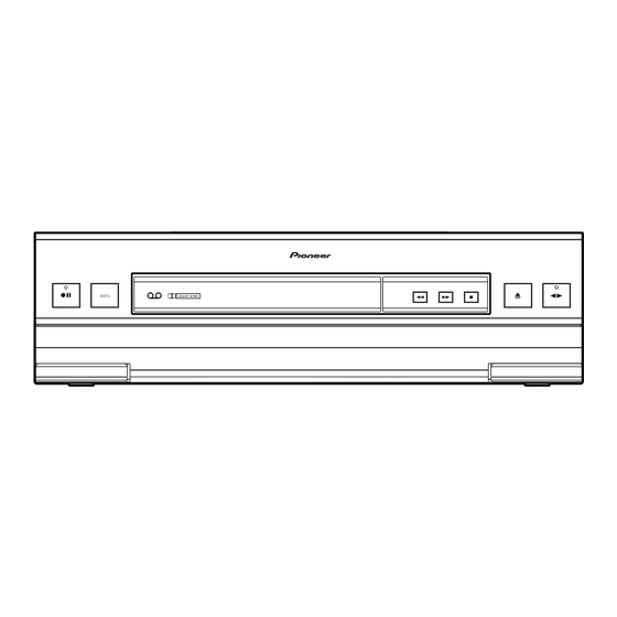
Page 27: Panel Facilities And Specifications
CT-L5 8. PANEL FACILITIES AND SPECIFICATIONS 7 PANEL FACILITIES 1 2 3 4 5 6 7 8 9 ¶ 8 Ÿ ASES DOLBY B NR ¡ 1 Recording pause button (¶ 8) 8 Cassette tray Open/Close button (0) 2 Rec indicator...
Need help?
Do you have a question about the CT-L5 and is the answer not in the manual?
Questions and answers