Table of Contents
Advertisement
Quick Links
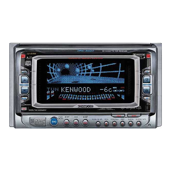
CD CASSETTE DSP RECEIVER
DPX-6020
QQ
3 7 63 1515 0
SERVICE MANUAL
Knob (CDEJ)
(K24-3778-03)
TE
L 13942296513
Panel assy
(A64-2427-21) : M
(A64-2468-21) : K
Bracket assy
(J19-5121-04) : K
www
.
Refer to the service manual D40-1132-05 (B51-7505-00)
for CASSETTE MECHANISM ASSY's information.
CD
EJECT
COMPACT
DIGITAL AUDIO
TEXT
ATT
CRSC
VOLUME
NAME
DISP
PWR
OFF
SRC
Knob (SRC)
(K24-3777-03)
Escutcheon assy
(B07-3046-04)
Escutcheon assy
(B07-3047-04) : K
x
ao
u163
y
i
2 9
8
CD CASSETTE DSP RECEIVER
DIGITAL DIRECT
Q Q
3
6 7
1 3
1 5
USER PRESET
OFF
AUD
SBF
SCRL/B NR
SCN
DSP
EQ
FNC
1
2
Badge
(B43-1284-04)
Screw set
(N99-1701-05) : M
(N99-1711-05) : K
Remote controller assy
(A70-0900-05)
co
.
9 4
2 8
©2001-7 PRINTED IN JAPAN
B51-7779-00 ( N ) 1741
Knob (CAEJ)
(K24-3779-03)
DOLBY B NR
CASSETTE
EJECT
ANGLE
RTN
DISC
ANGLE
0 5
8
2 9
9 4
COMP
DBB/SFC
POSI
KBS
SFC LEVEL
R.SIZE
RDM/BS
REP
D.SCN
M.RDM/MTL
3
4
5
6
Front glass
(B10-4088-11)
DC cord
(E30-4886-05)
m
9 9
2 8
9 9
Advertisement
Table of Contents

Subscribe to Our Youtube Channel
Related Manuals for Kenwood DPX-6020


Summary of Contents for Kenwood DPX-6020
- Page 1 CD CASSETTE DSP RECEIVER DPX-6020 3 7 63 1515 0 SERVICE MANUAL ©2001-7 PRINTED IN JAPAN B51-7779-00 ( N ) 1741 Refer to the service manual D40-1132-05 (B51-7505-00) for CASSETTE MECHANISM ASSY’s information. Knob (CDEJ) Knob (CAEJ) (K24-3778-03) (K24-3779-03) CD CASSETTE DSP RECEIVER...
- Page 2 3 7 6 3 1 5 1 5 0 L 1 3 9 4 2 2 9 6 5 1 3 u 1 6 3...
-
Page 3: Components Description
DPX-6020 COMPONENTS DESCRIPTION 3 7 63 1515 0 Synthesizer Unit (X14-6770-XX) Ref. Parts No. Name Function System µ-COM M30622MC-A65FP TDA7407 E-VOL, HPF, LPF, INV VOL, LOUD, TONE, BAL, FAD, FM NC, MPX L4943 Power Source IC Digital : 5V, Audio : 8V, Tuner : 8V AVR, P-CON TDA7435 System E’S... - Page 4 DPX-6020 COMPONENTS DESCRIPTION / MICROCOMPUTER’S TERMINAL DESCRIPTION 3 7 63 1515 0 Ref. Parts No. Name Function DTC144EUA Panel detection Panel voltage detection DTA144EUA CH1→2 switching When turned on, A8V is output. DTC144EUA CH1→2 switching When turned on, Q37 is turned on.
-
Page 5: Microcomputer's Terminal Description
DPX-6020 MICROCOMPUTER’S TERMINAL DESCRIPTION 3 7 63 1515 0 (X14-)IC1:System µ-com Pin Name Description Processing Operation REQC External CH reception request REQH External CH transmission request H: On PANT Power antennal control H: On PCON External amp power control H: On... - Page 6 DPX-6020 MICROCOMPUTER’S TERMINAL DESCRIPTION 3 7 63 1515 0 (X14-)IC1:System µ-com Pin Name Description Processing Operation SEL1 IC2III noise cancellation selection Power input Not in use L: Fixed Power input SEL2 IC2III noise cancellation selection SEL3 Location switching H: M, L: J Not in use.
- Page 7 DPX-6020 MICROCOMPUTER’S TERMINAL DESCRIPTION 3 7 63 1515 0 (X25-)IC4:Panel µ-com Pin Name Description Processing Operation GSO1 FL dot section data output terminal 1 GCLK FL dot section clock output terminal Not used. L : Fixed. REMO Remote control signal input...
- Page 8 DPX-6020 MICROCOMPUTER’S TERMINAL DESCRIPTION 3 7 63 1515 0 (X25-)IC4:Panel µ-com Pin Name Description Processing Operation Not used. L : Fixed. Power source terminal 60~62 Not used. L : Fixed. External memory read request L : Read L : Fixed.
-
Page 9: Panel Mechanism Description
DPX-6020 PANEL MECHANISM DESCRIPTION 3 7 63 1515 0 Panel Opening 1. When Open button(switch) is pressed, the motor Closing Behavior (PM1) rotates. 1. The motor rotates in reverse direction. 2. The rotation of the motor is transmitted forward 2. The arm assembly (604) goes up. When the lever (A) - Page 10 DPX-6020 PANEL MECHANISM DESCRIPTION 3 7 63 1515 0 Assembly (Close Position) 1. Align the arm assembly with the pin of the planetary gear (603). 2. Assembly these to the sub-chassis (606) along with the rail (612). 3. Align lever (614) hole and the hold of the chassis (601).
-
Page 11: Test Mode / Adjustment
DPX-6020 3 7 63 1515 0 TEST MODE / ADJUSTMENT How to enter the text mode Panel Mechanism Adjustment While pressing on 1 and 3 keys, press the RESET key. The mechanism detects the open/close position of the panel and writes it to the E2PROM. - Page 12 DPX-6020 3 7 63 1515 0 ADJUSTMENT Tuner Adjustment Item Input Side (SG) Tuner Setting Adjustment Method Setting S-Meter Adjustment 98.1MHz 0dev FM 98.1MHz Enter the test mode and select a FM source. 35dBµ (ANT Input) When Preset #6 is pressed while pressing Preset #1 in the test mode, adjustment is started.
- Page 13 PC BOARD (COMPONENT SIDE VIEW) 3 7 6 3 1 5 1 5 0 SYNTHESIZER UNIT X14-6770-XX (J74-1228-12) X14-6770-XX Address Address C213 C211 C212 10 6 C210 C222 R201 C229 C230 C233 C113 R200 Refer to the schematic diagram for the C100 values of resistors and capacitors.
- Page 14 PC BOARD (FOIL SIDE VIEW) 3 7 6 3 1 5 1 5 0 SYNTHESIZER UNIT X14-6770-XX (J74-1228-12) X14-6770-XX Address Address C217 C216 C215 C214 R191 R190 R189 R188 R184 R187 C219 R186 R185 R183 R181 R180 R182 Refer to the schematic diagram for the values of resistors and capacitors.
- Page 15 PC BOARD (COMPONENT SIDE VIEW) 3 7 6 3 1 5 1 5 0 (FOIL SIDE VIEW) SUB CIRCUIT UNIT SUB CIRCUIT UNIT DOLBY NOISE REDUCTION UNIT DOLBY NOISE REDUCTION UNIT X16-1400-20 (J74-1265-02) X16-1400-20 (J74-1265-02) X30-3000-00 (J74-0940-22) X30-3000-00 (J74-0940-22) 1 3 9 4 2 2 9 6 5 1 3 w w w X30-3000-00 X30-3000-00...
- Page 16 PC BOARD (COMPONENT SIDE VIEW) 3 7 6 3 1 5 1 5 0 (FOIL SIDE VIEW) SWITCH UNIT X25-9100-20 (J74-1271-12) SWITCH UNIT X25-9100-20 (J74-1271-12) X25-9100-20 X25-9100-20 Address Address Refer to the schematic diagram for the values of resistors and ca- pacitors.
- Page 17 PC BOARD (COMPONENT SIDE VIEW) 3 7 6 3 1 5 1 5 0 (FOIL SIDE VIEW) CD PLAYER UNIT CD PLAYER UNIT X32-5030-01 (J74-1161-02) X32-5030-01 (J74-1161-02) /MUTEL LO/EJ MOTOR /MUTER A.5V LOAD SLED+ EJECT/SLED- S.GND SPDL- S.+B /MSTOP /MRST R102 SPDL+ 1 3 9 4 2 2 9 6 5 1 3...
- Page 18 Values may vary slightly due to variations between individual instru- u 1 6 3 ments or/and units. DAP202U MA142WA 02CZ12-X 02CZ7.5-X DA227 LB1641 PST9142NR TC74HC4050AFT BA033LBSG UPC29L33T DA204K MA142WK 02CZ18-Y 02CZ8.2-Y DA204U 02CZ3.6-Z DTA114YUA 02CZ4.3-X 02CZ5.1-Y DPX-6020 02CZ6.2-X 02CZ6.8-Y...
- Page 19 3 7 6 3 1 5 1 5 0 (X14-6770-XX) UNIT DESTINATION R276 R277 REQ C R66 100 C2 0.01 0-11 DATA C R67 100 0-20 C1 4700u16 R70 100 DATA H R68 100 +11V +11V R69 4.7 0.47u50 +34V +34V R64 1K C86 47u6.3...
- Page 20 CONTROL u 1 6 3 CD DET DPX-6020 (1/2) CAUTION : For continued safety, replace safety critical components only with manufacturer's recommended parts (refer to parts list). DPX-6020 Indicates safety critical components. To reduce the risk of electric shock, leakage-current or resistance measurements shall be carried out (exposed parts are acceptably insulated from the supply circuit) before the appliance is returned to the customer.
- Page 21 FM-M(AUD) w w w • DC voltages are as measured with a high impedance voltmeter. Val- u 1 6 3 ues may vary slightly due to varia- tions between individual instruments 5.0V 5.0V 100K or/and units. 100K DPX-6020 DPX-6020 (2/2)
- Page 22 Indicates safety critical components. To reduce the risk of electric shock, leakage-current or resistance measurements shall be carried out (exposed parts are acceptably insulated DPX-6020 from the supply circuit) before the appliance is returned to the customer. • DC voltages are as measured with a high impedance voltmeter. Values may vary slightly...
- Page 23 DPX-6020 EXPLODED VIEW (CD MECHANISM) 3 7 63 1515 0 M1.7x2.5 : N09-4249-05 ¿2x3.5 : N09-4172-05 M1.7x4 : N09-4202-05 M2x2 : N38-2020-46 ¿2x6 : N09-4294-05 WASHER ¿1.2 : N19-2023-04 WASHER ¿1.6 : N19-2058-04 WASHER ¿1.6 : N19-2093-04 M2x2 : N39-2020-46...
- Page 24 DPX-6020 EXPLODED VIEW (PANEL MECHANISM) 3 7 63 1515 0 M1.7x2 (BLK) : N09-4343-08 M1.7x6 (BLK) : N38-4303-08 M2x2 (BLK) : N09-4341-08 M2x2 (BLK) : N09-4358-08 M2x2.5 (BLK) : N38-2025-45 M2.6x3 (BLK) : N38-2630-45 M2.6x4 : N32-2604-46 E-RING (φ1.5) : N29-0516-08 E-RING (φ2.5)
-
Page 25: Exploded View (Unit)
DPX-6020 EXPLODED VIEW (UNIT) 3 7 63 1515 0 M1.4 (BLK) : N09-4468-05 M2.6x3.5 : N09-4469-05 M2x3 : N09-4480-05 φ3x14 : N30-3014-46 φ3x10 (BLK) : N83-3010-46 φ3x5 (BLK) : N83-3005-46 φ2x6 : N09-4344-05 L 13942296513 (X14-) (X14-) (X14-) (X14-) (X14-) -
Page 26: Exploded View (Display)
DPX-6020 EXPLODED VIEW (DISPLAY) 3 7 63 1515 0 (X25-) L 13942296513 M1.4 : N09-4465-05 M1.4 (BLK) : N09-4466-05 M2x3 : N09-4467-05 φ2x6 : N80-2006-46 φ2x8 (BLK) : N80-2008-45 φ2x10 : N80-2010-46 u163 Parts with the exploded numbers larger than 700 are not supplied. -
Page 27: Parts List
DPX-6020 PARTS LIST 3 7 63 1515 0 New parts Parts without Parts No. are not supplied. Les articles non mentionnes dans le Parts No. ne sont pas fournis. Teile ohne Parts No. werden nicht geliefert. Desti- Desti- Ref. No. - Page 28 DPX-6020 PARTS LIST 3 7 63 1515 0 New parts Parts without Parts No. are not supplied. Les articles non mentionnes dans le Parts No. ne sont pas fournis. SYNTHESIZER UNIT (X14-6770-XX) Teile ohne Parts No. werden nicht geliefert. Desti- Desti- Ref.
- Page 29 DPX-6020 PARTS LIST 3 7 63 1515 0 New parts Par ts without Parts No. are not supplied. Les articles non mentionnes dans le Parts No. ne sont pas fournis. SYNTHESIZER UNIT (X14-6770-XX) Teile ohne Parts No. werden nicht geliefert.
- Page 30 DPX-6020 PARTS LIST 3 7 63 1515 0 New parts Parts without Parts No. are not supplied. Les articles non mentionnes dans le Parts No. ne sont pas fournis. SYNTHESIZER UNIT (X14-6770-XX) Teile ohne Parts No. werden nicht geliefert. Desti- Desti- Ref.
- Page 31 DPX-6020 PARTS LIST 3 7 63 1515 0 New parts Parts without Parts No. are not supplied. Les articles non mentionnes dans le Parts No. ne sont pas fournis. SYNTHESIZER UNIT (X14-6770-XX) Teile ohne Parts No. werden nicht geliefert. Desti- Desti- Ref.
- Page 32 DPX-6020 PARTS LIST 3 7 63 1515 0 New parts Parts without Parts No. are not supplied. Les articles non mentionnes dans le Parts No. ne sont pas fournis. SWITCH UNIT (X25-9100-20) Teile ohne Parts No. werden nicht geliefert. Desti- Desti- Ref.
- Page 33 DPX-6020 PARTS LIST 3 7 63 1515 0 New parts Par ts without Parts No. are not supplied. Les articles non mentionnes dans le Parts No. ne sont pas fournis. Teile ohne Parts No. werden nicht geliefert. Desti- Desti- Ref. No.
- Page 34 DPX-6020 PARTS LIST 3 7 63 1515 0 New parts Parts without Parts No. are not supplied. Les articles non mentionnes dans le Parts No. ne sont pas fournis. Teile ohne Parts No. werden nicht geliefert. Desti- Desti- Ref. No.
- Page 35 DPX-6020 PARTS LIST 3 7 63 1515 0 New parts Parts without Parts No. are not supplied. Les articles non mentionnes dans le Parts No. ne sont pas fournis. CD MECHANISM ASSY (X92-4100-01) Teile ohne Parts No. werden nicht geliefert.
- Page 36 DPX-6020 PARTS LIST 3 7 63 1515 0 CAPACITORS CC 45 TH 1H 220 J • Capacitor value Color* CC45 010 = 1pF 0 = 22pF 100 = 10pF 1 = Type … ceramic, electrolytic, etc. 4 = Voltage rating...
-
Page 37: Specifications
DPX-6020 3 7 63 1515 0 SPECIFICATIONS M type K type FM Section FM Section Frequency Range ......87.5MHz~108.0MHz (50kHz) Frequency Range ........87.9MHz~107.9MHz (Frequency Step) 87.9MHz~107.9MHz (200kHz) (Frequency Step) (200kHz) Channel Space Selection ........50kHz/200kHz Channel Space Selection ............–...
Need help?
Do you have a question about the DPX-6020 and is the answer not in the manual?
Questions and answers