Table of Contents
Advertisement
Quick Links
Advertisement
Table of Contents

Related Manuals for Tektronix cdm250


Summary of Contents for Tektronix cdm250
- Page 1 User Manual CDM250 Digital Multimeter 070-6736-03...
- Page 2 Copyright Tektronix, Inc. 1987. All rights reserved. Tektronix products are covered by U.S. and foreign patents, issued and pending. Information in this publication supercedes that in all previously published material. Specifications and price change privileges reserved. Tektronix, Inc., P.O. Box 1000, Wilsonville, OR 97070–1000...
- Page 3 Tektronix, with shipping charges prepaid. Tektronix shall pay for the return of the product to Customer if the shipment is to a location within the country in which the Tektronix service center is located. Customer shall be responsible for paying all shipping charges, duties, taxes, and any other charges for products returned to any other locations.
-
Page 5: Table Of Contents
Display On but CDM250 Not Displaying Reading ..Display On but CDM250 Does Not Read Current (10A) Appendix C: Replaceable Parts ..... . . - Page 6 ......Table 12: Accessory Power Cords ..... . CDM250 User Manual...
-
Page 7: General Safety Summary
Do Not Operate Without Covers To avoid electric shock or fire hazard, do not operate this product with covers or panels removed. Use Proper Fuse To avoid fire hazard, use only the fuse type and rating specified for this product. CDM250 User Manual... - Page 8 If you suspect there is damage to this product, have it inspected by qualified service personnel. Safety Terms and Symbols Terms in This Manual These terms may appear in this manual: WARNING. Warning statements identify conditions or practices that could result in injury or loss of life. CDM250 User Manual...
-
Page 9: Certifications And Compliances
Manual Certifications and Compliances CSA Certified Power Cords CSA Certification includes the products and power cords appropriate for use in the North America power network. All other power cords supplied are approved for the country of use. CDM250 User Manual... - Page 10 General Safety Summary CDM250 User Manual...
-
Page 11: Getting Started
The Tektronix CDM250 has a locking, multiposition handle that folds under the instrument to allow stacking with other instruments of the same series. The CDM250 is delivered with a set of test leads, a 115 V power cord, an installed line fuse for 115 V operation, and this manual. -
Page 12: Preparing The Digital Multimeter For Use
Getting Started Preparing the Digital Multimeter for Use Check the following items prior to operating the CDM250 Digital Multimeter for the first time (see Figure 1 for locations of items): Figure 1: Line Voltage Selectors, Power Input, and Fuse Locations CAUTION. - Page 13 4. Connect the input power cord. Use only power cords that are equipped with a third conductor that provide a safety ground connection. Use only the power cords specified for this equipment. Refer to Appendix C: Replaceable Parts on page 21 for power cord part numbers. CDM250 User Manual...
-
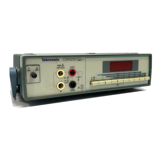
Page 14: Front Panel
Figure 2: Front Panel 1. POWER button. Powers the CDM250 on or off. Power ON is indicated by the LED display. 2. 10 A UNFUSED jack. Input connector for positive (red) test lead when instrument is used to measure high current (over 2 A but less than 10 A). - Page 15 AC or DC volts, ohms, and current functions. This connector is not connected to the power source ground through the instrument. 9. 2 A jack. Input connector for positive (red) test lead when instrument is used to measure current values up to 2 A. CDM250 User Manual...
- Page 16 Getting Started CDM250 User Manual...
-
Page 17: Reference
It also explains how use the CDM250 Digital Multimeter to check diodes. Preparations for Measurement 1. Be sure that the CDM250 Digital Multimeter is connected to a specified power source and that the LINE VOLTAGE SELEC- TORs are set to the proper position. Refer to Preparing the Digital Multimeter for Use on page 2. -
Page 18: Measuring Ac Or Dc Current
To measure direct current (DC), set the AC/DC button to the out position. 4. Push the A (amperes) button in. 5. Determine the highest anticipated current, and push in the corresponding range button. When the current value is unknown, start at the highest range. CDM250 User Manual... -
Page 19: Measuring Resistance
6. Connect the test leads, and read the display value. NOTE. When the component being tested is in a circuit where parallel current paths offer low resistance, the above test may require disconnecting one end of the component from the circuit. CDM250 User Manual... -
Page 20: Checking Diodes
NOTE. When the diode being tested is in a circuit where parallel current paths offer low resistance, the above tests may require disconnecting one end of the component from the circuit. CDM250 User Manual... -
Page 21: Appendix A: Specifications
64 mm (2.5 in) Depth 230 mm (9.0 in) Weight 1.8 kg (4.0 lb) Table 3: Environmental Characteristics Storage Temperature –10 C to 60 C, 80% RH Operating Temp +10 C to 40 C, 0 to 75% RH CDM250 User Manual... -
Page 22: Table 4: Electrical Characteristics
10 M + 1 digit) 1 mV 20 V 10 mV 200 V 100 mV 500 V Response Time Overload Protection 200 mV range: 500 VDC, 350 VAC 2 V to 500 V ranges: 500 VDC, 500 VAC CDM250 User Manual... -
Page 23: Table 6: Ac Volts Measurement Specifications
1 mA 1.1 V (1.0% of rdg ma im m maximum + 3 digits) 3 igits 10 A 10 mA Response Time Overload Protection 2 A range: 2 A, 250 V, fast-blow fuse 10 A range: None CDM250 User Manual... -
Page 24: Table 8: Alternating Current Measurement Specifications
10 A 200 mA 100 A 2000 mA 1 mA 1.1 V RMS ma im m maximum 10 A 10 mA Response Time Overload Protection 2 A range: 2 A, 250 V, fast-blow fuse 10 A range: None CDM250 User Manual... -
Page 25: Table 9: Resistance Measurement Specifications
50 A 200 k 2000 k 500 nA (1.5% of rdg 50 nA 20 M 10 k + 5 digits) Response Time to 2000 k ranges 15 s 20 M range Overload Protection 500 VDC or AC CDM250 User Manual... - Page 26 Electrical Fast Transient/Burst Immunity IEC 801-5 Power Line Surge Immunity The following degree of performance degradation is deemed acceptable by the manufacturer: Ambient RF fields of 3 V/m intensity may induce error up to 5% of reading. CDM250 User Manual...
-
Page 27: Appendix B: Maintenance
Appendix B: Maintenance This appendix provides information for the basic maintenance of the CDM250 Digital Multimeter. Cleaning To clean the digital multimeter, use a soft cloth dampened in a solution of mild detergent and water. Do not spray cleaner directly onto the instrument, since it may leak into the cabinet and cause damage. -
Page 28: Troubleshooting
No Display with Power On If the LED Display is not lighted, but the POWER button is pushed in and the CDM250 Digital Multimeter power cord is plugged into an outlet, do the following steps: WARNING. To prevent electrical shock, unplug the power cord and disconnect the test leads from any voltage source before checking or replacing the fuses. -
Page 29: Display On But Cdm250 Does Not Read Current (10A)
Appendix B: Maintenance Display On but CDM250 Does Not Read Current (10A) 1. Check that the function and range button selections are correct. 2. If function and range buttons are correct, contact the nearest Tektronix service center. CDM250 User Manual... - Page 30 Appendix B: Maintenance CDM250 User Manual...
-
Page 31: Appendix C: Replaceable Parts
Appendix C: Replaceable Parts Replaceable parts may be ordered directly from your authorized Tektronix dealer. Standard Accessories The following items are shipped with the CDM250 Digital Multimeter: Table 11: Standard Accessories Accessory Tektronix Part Number Fuse, 3AG, 0.125A, 250V, Slow Blow 159-0313-XX (90 –... -
Page 32: Table 12: Accessory Power Cords
Table 13: Accessory Power Cords Tektronix Part Plug Configuration Normal Usage Number North America 161-0104-00 115 V Europe 161-0104-06 230 V United Kingdom 161-0104-07 230 V Australia 161-0104-05 230 V North America 161-0104-08 230 V Switzerland 161-0167-00 230 V CDM250 User Manual...
Need help?
Do you have a question about the cdm250 and is the answer not in the manual?
Questions and answers