
Related Manuals for Trane CGA-SVX01A-EN


Summary of Contents for Trane CGA-SVX01A-EN
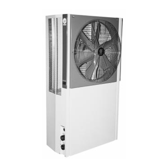
- Page 1 Installation Operation Maintenance Air-Cooled Cold Generator ® Air-Cooled Cold Generator ® With Heat Pump Option CGA-SVX01A-EN...
-
Page 2: Table Of Contents
UNIT WATER PRESSURE DROP FIGURE 6: HYDRAULIC CHARACTERISTIC PRE-START CHECKLIST OPERATION START-UP PROCEDURE EXTENDED UNIT SHUT-DOWN/WINTERIZATION STANDARD AMBIENT OPERATION OPTIONAL LOW AMBIENT OPERATION (CGAK) OPTIONAL HEAT PUMP OPERATION (CGAR) ELECTRICAL CONTROL & PROTECTION SYSTEM MAINTENANCE TROUBLE ANALYSIS © American Standard Inc. 2001 CGA-SVX01A-EN... -
Page 3: Model Nomenclature
C = Blue Fin + Standard Grille Cover 6=400V/50Hz/3Ph B = Blue Fin + Luxury Grille Cover (For model 050,075,100,125,150, 175, 200) 7=415V/50Hz/3Ph DIGIT 15 - Service Sequence (For model 050,075,100,125,150, 175, 200) A = First DIGIT 9 - Development Sequence D=Fourth Design CGA-SVX01A-EN... -
Page 4: Installation
Rig the unit using canvas belt. Fasten the belt to the unit over the unit’s WATER PIPING base as show in Figure 1. Thoroughly flush all water system piping before making the final piping connections to the unit. © American Standard Inc. 2001 CGA-SVX01A-EN... - Page 5 Figure - 1: Recommended Hoisting Arrangement (CGAK-075 As Shown) CGA-SVX01A-EN...
- Page 6 Figure - 2: Dimension for Mounting (CGAK-075 As Shown) Note: All Dimensions in Millimeter © American Standard Inc. 2001 CGA-SVX01A-EN...
- Page 7 Figure - 3: Service and Maintenance Clearance (CGAK-075 As Shown) CGA-SVX01A-EN...
-
Page 8: Electrical Wiring
(i.e. maximum working pressure). tion. For actual wiring diagram, refer to the Use an expansion tank to isolate this one fixed to the control panel cover. pressure if water pressure exceeds this value. © American Standard Inc. 2001 CGA-SVX01A-EN... - Page 9 Figure - 4: Typical Piping Arrangement (CGAK-075 As Shown) CGA-SVX01A-EN...
- Page 10 Figure - 5: Typical System Application (CGAK-075 And Fans As Shown) © American Standard Inc. 2001 CGA-SVX01A-EN...
-
Page 11: Electrical Data
• Recommended Fuse Size (REC) = Largest Load x 1.5 + Sum of additional Loads. (Select closest fuse size) • Maximum Fuse Size (MFS) = Largest Load x 2.25 + Sum of additional Loads. (Select equal or next lower fuse size) CGA-SVX01A-EN... -
Page 12: Flow Switch Interlock
FLOW SWITCH INTERLOCK Circuit Diagram: For CGAK 030 - 075 © American Standard Inc. 2001 CGA-SVX01A-EN... -
Page 13: Circuit Diagram For Cgar 030 - 075
Circuit Diagram: For CGAR 030 - 075 CGA-SVX01A-EN... -
Page 14: Circuit Diagram For Cgak 100 - 200
Circuit Diagram: For CGAK 100 - 200 © American Standard Inc. 2001 CGA-SVX01A-EN... -
Page 15: Circuit Diagram For Cgar 100 - 150
Circuit Diagram: For CGAR 100 - 150 CGA-SVX01A-EN... -
Page 16: Installation Checklist
In order to turn on/off the chiller from indoors, connect wiring across reserved terminals 2 & 3 in the unit control panel from an indoor REMOTE OFF/ON switch. © American Standard Inc. 2001 CGA-SVX01A-EN... -
Page 17: Pre-Start Procedure
Conversely, excessively high flow Va = (221 + 230 + 227)/3 = 226 Volts compressor motors. rate may cause erosion in the water system. then Vd = 221 Volts The percentage of imbalance is then: 100x 226-221 2.2% CGA-SVX01A-EN... -
Page 18: Unit Water Pressure Drop
I.P.L. curves. (Refer to 25.1 37.7 56.6 Figure 6 for hydraulic characteristics of all 37.3 56.0 84.0 models.) 49.1 73.7 110.6 62.1 93.3 140.0 74.4 111.7 150.0 85.5 128.3 160.0 98.3 149.0 190.0 © American Standard Inc. 2001 CGA-SVX01A-EN... - Page 19 Figure - 6: Hydraulic Characteristics - 60Hz CGA-SVX01A-EN...
- Page 20 Figure - 6: Hydraulic Characteristics - 50Hz © American Standard Inc. 2001 CGA-SVX01A-EN...
-
Page 21: Pre-Start Checklist
Adjust the water flow rate through the chilled water circuit, and check the external available water pressure of the unit (for standard unit) or the evaporator water pressure drop for the no-pump option unit. CGA-SVX01A-EN... -
Page 22: Operation
(for no built-in pump unit with field- adjustments for the expansion valve to compressor access panels. Replace and installed pump system). These readings stabilize at each new setting. tighten all retaining screws. should be stable at proper levels. © American Standard Inc. 2001 CGA-SVX01A-EN... -
Page 23: Extended Unit Shut-Down/Winterization
3. Remove compressor delay on timer(s) option will enable units to operate at outdoor (TR1, TR2). Record down the original ambient temperature down to 4°C (except socket for the respective timer so that the Model 100). correct timer(s) are replaced correctly later. CGA-SVX01A-EN... -
Page 24: Electrical Control & Protection System
EWT rises to 13.5 °C com- of a water temperature thermostat (WTT) pressor 2 comes on, and if EWT rises malfunction or restricted water flow. The further to 14.0°C, compressor 1 comes on. © American Standard Inc. 2001 CGA-SVX01A-EN... - Page 25 2 Minutes 2nd compressor On Delay Normally Open, Time Closed 3 Minutes Low Suction Pressure Override Delay TR3, TR4 Normally Closed, Time Open 2 Minutes Low Suction Pressure Override Delay TR3, TR4 Normally Closed, Time Open 1.5 Minutes (LAU Only) CGA-SVX01A-EN...
-
Page 26: Maintenance
Check fan set screws for tightness. properly insulated. Please clean up internal and pipe’s Clean condenser fan. strainer once the unit first starts running and monthly after use. © American Standard Inc. 2001 CGA-SVX01A-EN... -
Page 27: Trouble Analysis
Loose wiring connections (2) Defective compressor Check for the followings: a. Open motor winding b. Excessive amp draw on all phases (3) Insufficient starting voltage (Single-Phase Units Only) Check for the followings: a. Defective start capacitor b. Defective start relay CGA-SVX01A-EN... - Page 28 Restriction in liquid line (3) Improper voltage at compressor Check for the followings: a. Low or imbalanced line voltage b. Loose power wiring c. Defective compressor contactor (4) Internal parts of compressor damaged Replace compressor © American Standard Inc. 2001 CGA-SVX01A-EN...
- Page 29 (1) Excessive cooling load (i.e., high supply water temperatures) See (E) above (2) Expansion valve overfeeding (i.e.,superheat too low, liquid Adjust superheat setting; verify that remote bulb is properly attached flooding to compressor) to suction line (3) Suction valves broken (i.e. noisy compressor) Replace compressor CGA-SVX01A-EN...
- Page 30 (1) Low water flow Check for clogged strainers and incorrect balancing valve settings (2) Defective heating thermostat switch a. Verify that sense bulb is properly inserted bulbwell of heat-exchanger b. Replace heating thermostat switch © American Standard Inc. 2001 CGA-SVX01A-EN...
- Page 31 NOTE CGA-SVX01A-EN...
- Page 32 3600 Pammel Creek Road La Crosse, Wl 54601-7599 Stocking location Taipei Taiwan http : // www.trane.com Since The Trane Company has a policy of continuous product improvement, it reserves the right to change design and An American-Standard Company specifications without notice.
Need help?
Do you have a question about the CGA-SVX01A-EN and is the answer not in the manual?
Questions and answers