Tinkerine Studio Ditto Pro User Manual
Hide thumbs
Also See for Ditto Pro:
- Setup & operation manual (17 pages) ,
- Quick start manual (5 pages) ,
- Quick start manual (4 pages)
Table of Contents
Advertisement
Advertisement
Table of Contents

Related Manuals for Tinkerine Studio Ditto Pro


Summary of Contents for Tinkerine Studio Ditto Pro
- Page 1 U S E R M A N U A L...
- Page 2 Welcome. Congratulations on becoming the owner of a brand new Ditto Pro 3D printer. ™ This user manual will assist you with the unboxing and initial setup of the printer, and provide guidance on general maintenance and troubleshooting procedures. So welcome to the Tinkerine family, we hope you will enjoy using the Ditto Pro as much as we do.
-
Page 3: Table Of Contents
Table of Contents SAFETY WARNINGS WARRANTY SPECIFICATIONS PRINTER OVERVIEW UNBOXING FILAMENT INSTALLATION PRINT BED INSTALLATION PRINT BED CALIBRATION AND STARTING A PRINT BED LEVELING GUIDE TINKERINE SUITE SOFTWARE INSTALLATION IMPORTING AND PRINTING A MODEL SLICING SETTINGS EXPORTING A FILE MODEL ROTATION MODEL SCALING SLICING SETTINGS EXPLAINED MEASURING FILAMENT DIAMETER... -
Page 4: Safety Warnings
Safety Warnings FRAGILE The Ditto™Pro contains delicate electronic components and sensors. Handle with care. The Ditto™Pro 3D printer is not user serviceable. Hot Surface. Allow to cool before servicing. HOT SURFACE The Ditto™Pro 3D printer hotend heats up to high temperatures during operation. Allow the hotend to properly cool down before reaching in your hand. -
Page 5: Warranty
Warranty STANDARD WARRANTY Tinkerine Studios, LTD warrants the equipment and accessories comprising the Ditto™Pro 3D Printer will be free from defects in material and workmanship for one (1) year from the date of customer purchase. Original serial number must appear on product. Removal of serial numbers will void this warranty and any equipment and accessories that have been altered or modi ed in any way and are not as originally purchased will void this warranty. - Page 6 Safety Warnings Ditto™Pro 3D Printer Physical Dimensions 37 x 39 x 43.6 cm (14.6 x 15.4 x 17.2 in) Weight 10 kg (22.0 lb) Printing Build Volume 22 x 16.5 x 22 cm (8.7 x 6.5 x 8.7 in) Filament Diameter 1.75 mm Layer Resolution 50-300 microns (0.05-0.3 mm)
-
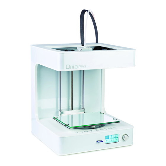
Page 7: Printer Overview
Printer Overview Filament Guide Tube Hotend FRONT Print Cooling Fan Print Bed SD Card Reader Control Dial Control Menu BACK Spool Holder Power Socket Power Switch USB Port... -
Page 8: Unboxing
Unboxing Peel back aps and remove compartment lid. USB Cable Power Cable Hex Wrench Glass Print Bed Print Bed Clips x4 SD Card Remove printer accessories from compartment. Remove foam bracket and remove the printer and lament. Place the printer on a rm at surface. Remove the printer and lament from the box. - Page 9 Unboxing Using a pair of scissors, cut away the two zip ties that are securing the extruder in place, and remove the printer certi cation card. DPR1234567 John Doe Use extra caution when cutting off the zip ties to prevent damage to the motion belts or wires. Powering On Make sure the power switch on the printer is in the Off position ( O ).
-
Page 10: Filament Installation
Filament Installation Extend the lament guide tube from the retracted position. Remove the lament spool from the packaging and place it on the spool holder. Take the end of the lament from the spool and insert it into the guide tube. If you are having trouble feeding the lament into the lament guide tube, pull the lament out and trim the tip of the lament with a pair of scissors. -
Page 11: Print Bed Installation
Print Bed Installation Place the glass print surface onto the bed with the blue painter’s tape side facing upward. The tape will act as an adhesion material for the plastic. With the clips provided in the accessory kit, slide each clip on to pinch the bed platform and glass print surface together. - Page 12 Print Bed Calibration WIZARD MAIN MENU Print Temp Control Wizard Status Bed Level New Filament Exit From the main menu, turn the dial to scroll to Wizard. Select the Bed Level option and follow the on-screen Push down on the dial to select. instructions to level the print bed.
-
Page 13: Bed Leveling Guide
Bed Leveling Guide To ensure that your prints always stick to the glass build plate, the build surface must be properly leveled so that the nozzle is at an equal set distance across the print surface. Use the Bed Leveling Wizard and follow the on-screen instructions to assist you in leveling the print bed. -
Page 14: Tinkerine Suite Software Installation
Tinkerine Suite Software Installation Out with the old and in with the new. The new Tinkerine Suite interface will streamline all its function on one convenient screen while de-cluttering the main screen by removing buttons that are not commonly used. From importing your 3D le to exporting it for your 3D printer, Tinkerine Suite allow you to have complete control of each le, allowing for multiple item printing, rotation, and scaling of each individual component. - Page 15 Importing a Model Importing a model within Tinkerine Suite Software To import a 3D model, click on the Import icon. In the dialogue box that appears, navigate to the directory where the model is saved, select the model and Open. Accepted mesh le formats: .STL , .OBJ Pre-sliced:...
- Page 16 Slice Settings Once you imported a 3D model, select the Settings button from the side bar to open up the slicing setting. Ditto™Pro 3D Printer PROFILE RESOLUTION Medium: 200 micron 1.75 INFILL FILAMENT WALL BRIM TEMP Hotend SUPPORT 70mm/s SPEED ANGLE A - Change resolution settings.
-
Page 17: Exporting A File
Exporting a File To export the model, press the Slice button on the side bar. This will begin the export process which generally takes a couple of minutes depending on the size of the model. Once slicing is completed, use the dialogue box to save the .GCODE le onto a SD card or le directory on your computer. -
Page 18: Model Rotation
Model Rotation Sometimes when you import a model it may not be facing the right way, with the rotate tool, you can adjust the rotational angle on each individual axis. In the rst image, you can see that the vase is lying on its side. Since we want to print it with the at base as the bottom, we'll use the Rotate Tool to correct this. - Page 19 Model Rotation Once the Rotate tool is activated, three rotational rings will envelope the 3D model, each individual ring will allow you to control one of the three rotational axis (X,Y,Z). In this example, we rotated the Y-axis ring to bring the model upright. To rotate, click on the axis you wish to wish to rotate on, hold down your left mouse button and drag until you are satis ed with the angle.
-
Page 20: Model Scaling
Model Scaling When importing in an oversized model that exceeds the printer’s print volume, the model will be shaded in gray. We can utilize the Scale Tool to adjust model sizes bigger or smaller. To scale uniformly, click on the scaling node (grey) and drag your mouse left or right until the model is at your desired size. - Page 21 Model Scaling UNIFORM 100% 100% 100% SCALING WIDTH DEPTH HEIGHT 74.5 64.2 54.8 RESET Percentage Control Scale the model using % scaling. Regardless of the original measurement, the model is set to 100% scale when you rst import it. Double the original size by typing in 200% or shrink the original size by half when you change the number to 50%.
-
Page 22: Slicing Settings Explained
Slicing Settings Explained Resolution Change resolution settings. Choose from 300, 200, 100, and 50 micron. Default set to Medium - 200 (0.2mm per layer). Printing at a lower resolution (300 micron) will allow for a faster print, while printing at higher resolutions (50 micron) will take the longest, but allow for the best nish. - Page 23 Slicing Settings Explained Support Activate support when you have steep angles or overhanging structures on your model; there are two modes of support: Ext Mode (Builds support on the exterior of the object): This mode is useful when you don’t want support structures in every nook and cranny of your model, and only on the exterior where it’s easier to remove.
- Page 24 Model Rotation Speed This sets the printing speed of the printer. Recommended speed range is 50-70 mm/s for best printing quality. Temperature This sets the temperature to which the hotend heats up to. For Tinkerine 1.75 PLA lament, set the hotend temperature to 215-220 degrees Celsius. Brim Turning on the Brim printing feature in the settings menu will add a one layer brim to the edges of your printed model .
-
Page 25: Measuring Filament Diameter
Measuring the Filament Diameter Measuring the lament diameter with a digital caliper and inputting that information into Tinkerine Suite will allow you to achieve the best quality from your prints. Follow the steps below to mea- sure your lament. 1. Make sure to zero your caliper in its closed 2. -
Page 26: Updating Printer Firmware
Updating Printer Firmware From time to time, you will want to download the rmware updates for your Ditto™Pro 3D Printer. These updates will aim to address overall printer performance and speci c software usability issues. Follow the steps below to update your printer rmware. 1. - Page 27 Updating Printer Firmware 5. Allow the rmware to upload to the printer. 6. All done! Click Ok to close the window and Do not disconnect the cable at this time. you can now disconnect the USB cable from the printer and computer.
-
Page 28: Troubleshooting
Troubleshooting Printing Issues ISSUE SOLUTION Cannot insert lament into the Ditto™Pro 3D Remove the lament, trim off the tip off the lament with a pair of Printer extruder. scissors and try loading the lament again. With one hand, grab the end of the lament and insert it into the extruder. - Page 29 Troubleshooting Printer Issues ISSUE SOLUTION Prints do not stick to the bed despite using the The bed-leveling wizard will serve as a good reference point to bed-leveling wizard. which to level your bed. Depending on the accuracy of the calibra- tion, you may need to make micro adjustments once the printer begins a print.
- Page 30 Troubleshooting Software Issues ISSUE SOLUTION Printer driver not recognized when connected to Install the Tinkerine Suite slicing software to obtain the required the computer. drivers for the printer connection. To install the drivers manually, navigate the Tinkerine Suite slicing software directory: C:/Program Files(x86)/Tinkerine Suite/drivers/ Run dpinst32 or dpinst64 depending on if the computer is running a 32bit or 64bit OS.
-
Page 31: Printer Care Maintenance
Printer Care and Maintenance Filament Care INSTALLING THE SPOOL: Rest the spool on the spool holder on the back of the printer. Make sure the spool will spin clockwise as the lament feeds into the guide tube. WHEN NOT IN USE: Retract the lament and coil back onto the spool. - Page 32 Printer Care and Maintenance Gantry Linear Bearing + Rod Lubrication BEFORE YOU BEGIN: Only use machining oil on the X+Y axis smooth rods and linear bearings. Grease based lubricant can seize and damage linear bearings. Apply a single drop on each of the smooth rods and manually move the carriage around so the machining oil can seep into the linear bearings and bushings.
- Page 33 Printer Care and Maintenance Screw Rod Lubrication APPLYING GREASE: 1. Grasp both sides of the build platform and push it up or downward to expose as much of the threaded rod as possible. 2. Clean off the rod by wiping off excess grim and dirt with a cloth. 3.
- Page 34 Printer Care and Maintenance Drive Gear Cleaning Overtime, lament bits may accumulate in the drive gear’s teeth, causing the gear to lose grip on the lament. In this situation, we will need to remove the drive gear from the extruder and clean off the lament debris. With a 1.75mm hex key, insert it from the top of the extruder cap and rotate the motor shaft to line up the set screw with the hex key.
-
Page 35: Hotend Replacement
Hotend Replacement Before You Begin Hotend swaps are performed to replace a hotend that is fully/partially jammed. A partially jammed hotend will affect the print quality and leave striations on the print surface. Go through the checklist below to see if there may be other issues before resorting to a hotend swap. - Page 36 Hotend Replacement MAKE SURE TO REMOVE ANY FILAMENT IN THE HOTEND AND ALLOW THE HOTEND TO COOL DOWN BEFORE PERFORMING THE SWAP. Hot Surface. Allow to cool before servicing. Pinch Point. Keep hands and fingers clear. Electric Shock Hazard. This equipment is to be serviced by trained personnel only.
- Page 37 Hotend Replacement Move the right print bed cooling fan to give enough clearance to the hotend. Pull down on the hotend and retract the unit out of the seating. With the hotend still attached to the thermistor and heater cartridge wire, swing the hotend around the backside of the cooling fan panel to expose the wires.
- Page 38 Hotend Replacement Using the 1.75mm hex key, loosen the heater cartridge set screw located on the back of the hotend heater block. With the setscrew loosened, remove the heater cartridge from the hotend.
- Page 39 Hotend Replacement Remove the thermistor from the heater block by unscrewing the bronze setscrew by hand. Take the new hotend unit and screw the thermistor back into the heater block by hand. Avoid screwing in the thermistor setscrew with tools to prevent causing damage to the thermistor bulb.
- Page 40 Hotend Replacement Insert the heater cartridge back into the right side of the heater block. Orientate the heater cartridge wires so they point toward the back of the extruder. Use the 1.75mm hex key to tighten the setscrew that secure the heater cartridge in place.
- Page 41 Hotend Replacement Carefully thread the cooling fan panel in between the heater cartridge and thermistor wire. Once the components are in place, the thermistor wires should go around the back of the hotend heater block, and both wires from the cartridge and thermis- tor will come under and out from the cooling fan mount.
- Page 42 Hotend Replacement Insert the hotend mount back into the carriage. Insert both hotend mount screws in. You will need to push from the bottom of the hotend mount to align the mounting holes.
- Page 43 Hotend Replacement Tighten both mounting screws. Screw all three blower fan mounting screws back into the panel. Ensure the wiring is routed as shown in the picture and obstruction free during printing.
-
Page 44: Glossary
Glossary BLUE TAPE: FILAMENT GUIDE TUBE: Blue painter’s tape that acts as an adhesion layer for models A plastic tube that acts as a channel for the PLA lament to to be printed on. Find blue tape at your local hardware store. go from the spool into the top of the extruder. - Page 45 Glossary SD CARD READER: Located on the front panel of the printer. Load your sliced model les onto the supplied SD card and insert it into the reader slot. Select a le from the LCD menu to start a print. SLICING: The process of exporting your 3D models into a 3D print ready le for your printer.
Need help?
Do you have a question about the Ditto Pro and is the answer not in the manual?
Questions and answers