Table of Contents
Advertisement
Installation and Operation Instructions
These instructions are to be stored in the packet provided on the boiler.
FOR YOUR SAFETY: This product must be installed and serviced by a professional service technician,
qualified in hot water boiler installation and maintenance. Improper installation and/or operation could
create carbon monoxide gas in flue gases which could cause serious injury, property damage, or death.
Improper installation and/or operation will void the warranty.
If the information in this manual is not followed exactly, a fire or explosion may result
causing property damage, personal injury or loss of life.
Do not store or use gasoline or other flammable vapors and liquids in the vicinity of this or
any other appliance.
• Do not try to light any appliance.
• Do not touch any electrical switch; do not use any phone in your building.
• Immediately call your gas supplier from a nearby phone. Follow the gas supplier's
instructions.
• If you cannot reach your gas supplier, call the fire department.
Installation and service must be performed by a qualified installer, service agency, or gas
supplier.
Vent damper is optional in some provinces of Canada.
WHAT TO DO IF YOU SMELL GAS
Installation
and Operation
Instructions for
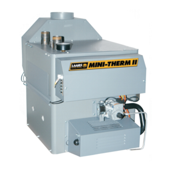
Mini-Therm II
Residential
Gas-Fired
Hydronic Boilers
Model JV
Sizes 50-225
WARNING
Document 1025W
Advertisement
Table of Contents
Troubleshooting

Related Manuals for Laars Mini-Therm II JV


Summary of Contents for Laars Mini-Therm II JV
-
Page 1: Installation And Operation
Installation and Operation Instructions Document 1025W Installation and Operation Instructions for Mini-Therm II Residential Gas-Fired Hydronic Boilers Model JV Sizes 50-225 Vent damper is optional in some provinces of Canada. These instructions are to be stored in the packet provided on the boiler. FOR YOUR SAFETY: This product must be installed and serviced by a professional service technician, qualified in hot water boiler installation and maintenance. -
Page 2: Table Of Contents
LAARS HEATING SYSTEMS Page 2 TABLE OF CONTENTS Electrical Wiring .......... 10 SECTION 1. Filling the System ........12 General Information Introduction ........... 3 SECTION 2. Warranty ............3 Installation Instructions Field Assembly ..........3 2A-1. System Start-up .......... 14 Flow Requirements ........ -
Page 3: General Information
Heater, refer also to Document 8001, Mini-Combo II Installation and Operation Instructions. Vent The Laars automatic vent dampers are standard Damper on all U.S. models. The Laars side wall power venters (optional in Vent Canada) Damper can be used on both JVS and JVT models. Special... -
Page 4: Flow Requirements
Failure to insure proper water flow through the In Canada, refer to the latest edition of CAN/CGA- heat exchanger of the boiler will void the Laars B149.1 and 2. warranty. Flow can be verified by measuring the... -
Page 5: Gas Supply And Piping
American from Laars, is used. See the boiler rating plate for the Insurance Code. This code specifies the surface under appropriate base part number. Boilers must never be the boiler be protected with hollow masonry no less installed on carpeting. -
Page 6: Combustion Air Supply
LAARS HEATING SYSTEMS Page 6 Disconnect the boiler from the gas supply pipe In general, these requirements specify that boiler before pressure testing the pipe for gas leaks. rooms which represent confined spaces should be Provide gas supply pressure to the boiler as provided with two permanent air supply openings;... -
Page 7: Venting
Mini-Therm II Hydronic Boiler Page 7 Outside Air Supply: When combustion air is 1H. Venting supplied directly through an outside wall, each opening The draft diverter outlet is to be connected to an should have a minimum free area of one square inch per unobstructed vent pipe of the same or larger diameter, 4,000 BTU/h (1.2kW) input of the total input rating of terminating outside the building. -
Page 8: Common Venting System
A properly sized expansion tank must be Test for spillage at the draft hood relief opening included in the system. Laars offers an aircharged after 5 minutes of main burner operation. Use the diaphragm-type expansion tank, with an automatic... - Page 9 Mini-Therm II Hydronic Boiler Page 9 Air Cushion Type Expansion Tank Optional Feed Water Inlet Purge System Bypass Valve Bypass Valve (Ball Valve) (Ball Valve) Zone Pump Zone Pump Air Scoop Multi-Zone Feed Feed Valve System Water Optional Water Inlet Inlet Pump Air Scoop...
-
Page 10: Chilled Water Systems
When using a Laars or field supplied power boiler with appropriate valves to prevent the chilled venter, the proving switch must be connected in medium from entering the heating boiler. - Page 11 Mini-Therm II Hydronic Boiler Page 11 Figure 9a. Wiring Diagram, Spark Ignition System (JVS). A means of disconnecting the electrical supply must be provided within sight of the boiler. The pump and boiler must be wired as shown to insure that the pump is running whenever the boiler is firing.
-
Page 12: Filling The System
LAARS HEATING SYSTEMS Page 12 Figure 9c. Wiring Diagram, Standing Pilot System (JVT). switch. The boiler will not fire unless the pump is running and the flow switch is closed. Field installed safety devices and operating controllers, such as a valve end switch, draft switches,... - Page 13 Mini-Therm II Hydronic Boiler Page 13 Wiring with Taco Zone Valves Wiring with Honeywell Zone Valves Wiring with Multiple Zone Pumps For primary/secondary pumping: Connect to "W" in lieu of "A." Boiler relay is used for boiler pump and connection to "W" will energize boiler pump when any zone is calling for heat.
-
Page 14: System Start-Up
LAARS HEATING SYSTEMS Page 14 pressure regulator is also installed in the line, SECTION 2 adjust it to the same pressure. Operation and Maintenance Close all gate valves. Purge one circuit at a time 2A-1. System Start-Up as follows: Open one circuit drain valve and let water drain out for at least 5 minutes. -
Page 15: High Altitude Burner
Mini-Therm II Hydronic Boiler Page 15 BEFORE LIGHTING smell all around the Replace the louvered airbox cover and tighten appliance area for gas. Be sure to smell next to the two thumb screws securely. the floor because some gas is heavier than air 10. -
Page 16: Sequence Of Operation
LAARS HEATING SYSTEMS Page 16 On each affected burner, slowly close the air 2C. Maintenance shutter until a normal flame is observed then re- Lubricate the water circulating pump per the tighten its associated locking screw. instructions on the pump. -
Page 17: Electrical Troubleshooting
Mini-Therm II Hydronic Boiler Page 17 10. Low water cutoffs should be inspected and the pump relay and the "A" connection on the flushed periodically. terminal board; and from the purple wire termi- nal on the pump relay to the "W" connection on Note: The Warranty does not cover damage the terminal board. - Page 18 LAARS HEATING SYSTEMS Page 18 Symptom Cause Remedy Pump not A. No power A. Check circuit breakers and power source. operating B. Pump defective B. Replace. C. Incorrectly wired C. Recheck wiring diagrams. Pilot outage A. Inlet gas pressure too low A.
-
Page 19: Troubleshooting Honeywell S8600 Intermittent Pilot System
Mini-Therm II Hydronic Boiler Page 19 Troubleshooting Honeywell S8600 Intermittent Pilot System Some heaters may be equipped with an ignition module that shuts off pilot gas if pilot fails to light. To reset, interrupt power to heater Start Note: Before troubleshooting, familiarize yourself with the start-up and checkout procedure. -
Page 20: Glossary Of Terms
The section(s) of supply and return piping, including Side Wall Power Venter the heat distribution units (see below), connected This Laars accessory allows the boiler exhaust to be directly to the trunk. Also referred to as a "zone." routed horizontally through an adjoining outside wall,... -
Page 21: Parts List
Mini-Therm II Hydronic Boiler Page 21 SECTION 3. Parts List and Ordering Information Part Number Description Model, Size JVS-50 JVT-50 JVS-75 JVT-75 JVS-100 JVT-100 JVS-125 JVT-125 Pilot Gas System Pilot Assembly (Nat.) W0030600 W0040900 W0030600 W0040900 W0030600 W0040900 W0030600 W0040900 Pilot Assembly (LP) W0039600 W0040901... - Page 22 *Optional in Canada TO OBTAIN OR ORDER PARTS: Check with your nearest Laars dealer or distributor. They have many of the commonly needed parts in stock. If your dealer cannot supply you, contact the Service Department at Laars. See address and telephone information on back page of this document.
- Page 23 Mini-Therm II Hydronic Boiler Page 23 Figure 13 - Parts Identification Figure 13. Parts Identification.
- Page 24 6000 Condor Drive, Moorpark, CA 93021 • 805.529.2000 • FAX 805.529.5934 20 Industrial Way, Rochester, NH 03867 • 603.335.6300 • FAX 603.335.3355 480 S. Service Road West, Oakville, Ontario, Canada L6K 2H4 • 905.844.8233 • FAX 905.844.2635 www.laars.com Litho in U.S.A. © Laars Heating Systems 0011 Document 1025W...
Need help?
Do you have a question about the Mini-Therm II JV and is the answer not in the manual?
Questions and answers