Table of Contents
Advertisement
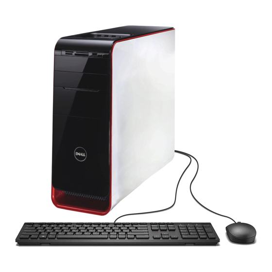
Dell Studio XPS™ 435T/9000 Service Manual
Technical Overview
Before You Begin
Replacing the Computer Cover
Replacing the Front Panel
Replacing the Badge Back Light
Replacing Memory Module(s)
Replacing Drives
Replacing a PCI Express Card
Notes, Cautions, and Warnings
NOTE:
A NOTE indicates important information that helps you make better use of your computer.
CAUTION:
A CAUTION indicates either potential damage to hardware or loss of data and tells you how to avoid the problem.
WARNING:
A WARNING indicates a potential for property damage, personal injury, or death.
Information in this document is subject to change without notice.
© 2009 Dell Inc. All rights reserved.
Reproduction of these materials in any manner whatsoever without the written permission of Dell Inc. is strictly forbidden.
Trademarks used in this text: Dell, the DELL logo, and Studio XPS are trademarks of Dell Inc.; Intel is a registered trademark of Intel Corporation in the U.S. and other countries;
Microsoft, Windows, Windows Vista, a n d Windows Vista start button logo are either trademarks or registered trademarks of Microsoft Corporation in the United States and/or other
countries.
Other trademarks and trade names may be used in this document to refer to either the entities claiming the marks and names or their products. Dell Inc. disclaims any
proprietary interest in trademarks and trade names other than its own.
Model: DCRM
July 2009 Rev. A01
Replacing Fans
Replacing the Processor
Replacing the System Board
Replacing the Battery
Replacing the Power Supply
Replacing the Top Cover
Replacing the I/O Panel
System Setup
Advertisement
Table of Contents

Related Manuals for Dell Studio XPS 435T / 9000


Summary of Contents for Dell Studio XPS 435T / 9000
- Page 1 Reproduction of these materials in any manner whatsoever without the written permission of Dell Inc. is strictly forbidden. Trademarks used in this text: Dell, the DELL logo, and Studio XPS are trademarks of Dell Inc.; Intel is a registered trademark of Intel Corporation in the U.S. and other countries;...
- Page 2 Replacing the Badge Back Light Dell Studio XPS™ 435T/9000 Service Manual WARNING: Before working inside your computer, read the safety information that shipped with your computer. For additional safety best practices information, see the Regulatory Compliance Homepage at www.dell.com/regulatory_compliance. 1. Follow the procedures in Before You Begin.
-
Page 3: Before You Begin
A component can be replaced or—if purchased separately—installed by performing the removal procedure in reverse order. Technical Specifications For information on technical specifications of your computer, see the Setup Guide that shipped with your computer or see the Dell Support website at support.dell.com. - Page 4 1. Ensure that the work surface is flat and clean to prevent the computer cover from being scratched. 2. Turn off your computer (see Turning Off Your Computer). CAUTION: To disconnect a network cable, first unplug the cable from your computer and then unplug the cable from the network device. ...
-
Page 5: Replacing A Pci Express Card
WARNING: Before working inside your computer, read the safety information that shipped with your computer. For additional safety best practices information, see the Regulatory Compliance Homepage at www.dell.com/regulatory_compliance. 1. To remove a PCI card, uninstall the PCI Express card's driver and software from the operating system. - Page 6 6. For a PCI card, grasp the card by its top corners, and then ease it out of its connector. 7. For a PCI Express x16 card, push the securing tab and grasp the card by its top corners. Ease the card out of its connector. PCI Express x16 card securing tab PCI Express x1 card...
- Page 7 14. Press and push the tabs of the PCI support bracket until its clicks into the filler brackets. PCI support bracket filler bracket 15. Press the tabs and push the expansion card retainer until it clicks into place. ...
-
Page 8: Replacing The Battery
WARNING: Before working inside your computer, read the safety information that shipped with your computer. For additional safety best practices information, see the Regulatory Compliance Homepage at www.dell.com/regulatory_compliance. WARNING: A new battery can explode if it is incorrectly installed. Replace the battery only with the same or equivalent type recommended by the manufacturer. -
Page 9: Replacing The Computer Cover
WARNING: Before working inside your computer, read the safety information that shipped with your computer. For additional safety best practices information, see the Regulatory Compliance Homepage at www.dell.com/regulatory_compliance. WARNING: To guard against likelihood of electric shock, laceration by moving fan blades or other unexpected injuries, always unplug your computer from the electrical outlet before removing the cover. -
Page 10: Replacing The Processor
WARNING: Before working inside your computer, read the safety information that shipped with your computer. For additional safety best practices information, see the Regulatory Compliance Homepage at www.dell.com/regulatory_compliance. CAUTION: Do not perform the following steps unless you are familiar with hardware removal and replacement. Performing these steps incorrectly could damage your system board. - Page 11 processor cover alignment notch (2) processor socket center cover latch release lever processor pin-1 indicator 9. If the release lever on the socket is not fully extended, move it to that position. CAUTION: You must position the processor correctly in the socket to avoid permanent damage to the processor and the computer when you turn on the computer.
- Page 12 Back to Contents Page ...
-
Page 13: Replacing The Hard Drive
Replacing the Metal Filler WARNING: Before working inside your computer, read the safety information that shipped with your computer. For additional safety best practices information, see the Regulatory Compliance Homepage at www.dell.com/regulatory_compliance. NOTE: The system board does not support IDE devices. NOTE: The 3.5-inch FlexDock is not interchangeable with the hard drive carrier. -
Page 14: Replacing The Optical Drive
5. Slide the drive out towards the back of the computer. 6. To replace the hard drive, check the documentation for the drive to verify that it is configured for your computer. 7. Slide the hard drive into the hard drive bay. ... -
Page 15: Replacing The Media Card Reader
9. Insert the optical drive into the chassis and slide it into place. 10. Align the screw holes in the optical drive with the screw holes in the optical drive bay. 11. Replace the two screws that secure the optical drive to the chassis. ... - Page 16 system board connector power cable data cable Media Card Reader screw 7. If you are not replacing the Media Card Reader go to step 8. If you are replacing the Media Card Reader or installing a new one, slide the Media Card Reader into place. ...
- Page 17 power cable screws (2) FlexDock USB cable 8. If you are not replacing the FlexDock, replace the metal filler if applicable (see Replacing the Metal Filler) and proceed with step 9. If you are installing a new FlexDock: a.
- Page 18 6. Push the tabs to lock the FlexDock drive insert. front panel tabs(2) FlexDock drive insert Replacing the Metal Filler CAUTION: To comply with FCC regulations, it is recommended that you replace the metal filler whenever the FlexDock or optical drive is removed from the computer.
- Page 19 5. To replace the metal filler, align the metal filler along the edges of the empty slot of the FlexDock or an optical drive and push the metal filler until it locks into place. Back to Contents Page ...
-
Page 20: Replacing The Chassis Fan
Replacing the Front Fan WARNING: Before working inside your computer, read the safety information that shipped with your computer. For additional safety best practices information, see the Regulatory Compliance Homepage at www.dell.com/regulatory_compliance. Replacing the Chassis Fan CAUTION: Do not touch the fan blades when you are removing the chassis fan. This could damage the fan. - Page 21 WARNING: Despite having a plastic shield, the processor fan and heat sink assembly may be very hot during normal operation. Ensure that it has had sufficient time to cool before you touch it. CAUTION: The processor fan and heat sink assembly is a single unit. Do not try to remove the fan separately. ...
-
Page 22: Replacing The Front Fan
11. Connect the processor fan and heat sink assembly cable to the connector (CPUFAN1) on the system board (see System Board Components). 12. Replace the computer cover (see Replacing the Computer Cover). 13. Connect your computer and devices to electrical outlets, and turn them on. Replacing the Front Fan ... -
Page 23: Replacing The Front Panel
Replacing the Front Panel Dell Studio XPS™ 435T/9000 Service Manual WARNING: Before working inside your computer, read the safety information that shipped with your computer. For additional safety best practices information, see the Regulatory Compliance Homepage at www.dell.com/regulatory_compliance. 1. Follow the procedures in Before You Begin. -
Page 24: Replacing Memory Module(S)
Replacing Memory Module(s) Dell Studio XPS™ 435T/9000 Service Manual WARNING: Before working inside your computer, read the safety information that shipped with your computer. For additional safety best practices information, see the Regulatory Compliance Homepage at www.dell.com/regulatory_compliance. 1. Follow the procedures in Before You Begin. - Page 25 cutouts (2) memory module notch tab on the memory module connector CAUTION: To avoid damage to the memory module, press the module straight down into the connector while you apply equal force to each end of the module. 8.
-
Page 26: Replacing The Power Supply
WARNING: Before working inside your computer, read the safety information that shipped with your computer. For additional safety best practices information, see the Regulatory Compliance Homepage at www.dell.com/regulatory_compliance. WARNING: To guard against likelihood of electric shock, laceration by moving fan blades or other unexpected injuries, always unplug your computer from the electrical outlet before removing the cover. - Page 27 8. Reconnect the DC power cables to the system board and drives. NOTE: Double-check all cable connections to make sure they are secure. 9. Replace the computer cover (see Replacing the Computer Cover). 10. Connect your computer and devices to electrical outlets, and turn them on. Back to Contents Page ...
-
Page 28: Replacing The System Board
WARNING: Before working inside your computer, read the safety information that shipped with your computer. For additional safety best practices information, see the Regulatory Compliance Homepage at www.dell.com/regulatory_compliance. CAUTION: Do not perform the following steps unless you are familiar with hardware removal and replacement. Performing these steps incorrectly could damage your system board. - Page 29 9. Remove the nine screws that secure the system board to the chassis. 1 screws (9) 2 system board 10. Lift the system board up and out. CAUTION: If you are replacing the system board, visually compare the replacement system board to the existing system board to ensure that you have the correct part.
- Page 30 1. Turn on (or restart) your computer. 2. When the blue DELL™ logo is displayed, watch for the F2 prompt to appear and then press <F2> immediately. NOTE: The F2 prompt indicates that the keyboard has initialized. This prompt can appear very quickly, so you must watch for it to display, and then press <F2>. If you press <F2> before you are prompted, this keystroke will be lost. If you wait too long and the operating system logo appears, continue to wait until you see the Microsoft® Windows® desktop.
- Page 31 Indicates the amount of installed memory in MB. Memory Installed Indicates the amount of memory available in MB. Memory Available Indicates the memory technology; DDR3. Memory Technology Indicates the memory speed in MHz. Memory Speed CPU Information Displays type of CPU. Genuine Intel (R) CPU Displays the CPU ID/micro code.
- Page 32 Changing Boot Sequence for the Current Boot You can use this feature to change the current boot sequence, for example, to boot from the CD/DVD drive to run the Dell Diagnostics on the Drivers and Utilities media. On completion of diagnostic tests, the previous boot sequence is restored.
-
Page 33: Clearing Forgotten Passwords
WARNING: Before working inside your computer, read the safety information that shipped with your computer. For additional safety best practices information, see the Regulatory Compliance Homepage at www.dell.com/regulatory_compliance. WARNING: The computer must be disconnected from the electrical outlet to clear the Password setting. -
Page 34: Flashing The Bios
2. Locate the BIOS update file for your computer at the Dell Support website at support.dell.com. NOTE: For non U.S. regions, choose your country/region from the drop-down list at the bottom of the Dell support website and then locate the BIOS update file for your computer. - Page 35 The file icon appears on your desktop and is titled the same as the download BIOS update file. 8. Double-click the file icon on the desktop and follow the instructions on the screen. Flashing the BIOS From a CD ...
-
Page 36: Technical Overview
System Board Components WARNING: Before working inside your computer, read the safety information that shipped with your computer. For additional safety best practices information, see the Regulatory Compliance Homepage at www.dell.com/regulatory_compliance. Inside View of Your Computer power supply optical drive... - Page 37 processor socket (CPU) memory module connector (DIMM2) processor fan connector (CPUFAN1) memory module connector (DIMM1) memory module connector memory module connector (DIMM4) (DIMM3) memory module connector (DIMM6) memory module connector (DIMM5) main power connector (PWR2) 10 battery socket (BAT1) 11 serial ATA drive connector (SATA1_2) 12 serial ATA drive connector (SATA3_4) 13 serial ATA drive connector (SATA5)
- Page 38 Reproduction of these materials in any manner whatsoever without the written permission of Dell Inc. is strictly forbidden. Trademarks used in this text: Dell, the DELL logo, and Studio XPS are trademarks of Dell Inc.; Intel is a registered trademark of Intel Corporation in the U.S. and other countries;...
-
Page 39: Replacing The Top Cover
Replacing the Top Cover Dell Studio XPS™ 435T/9000 Service Manual WARNING: Before working inside your computer, read the safety information that shipped with your computer. For additional safety best practices information, see the Regulatory Compliance Homepage at ww.dell.com/regulatory_compliance. 1. Follow the procedures in Before You Begin. - Page 40 8. Remove the I/O panel (see Replacing the I/O Panel). 9. Set the computer top cover aside in a secure location. 10. To replace the top cover, perform the removal procedure in reverse order. Back to Contents Page ...
-
Page 41: Replacing The I/O Panel
Replacing the I/O Panel Dell Studio XPS™ 435T/9000 Service Manual WARNING: Before working inside your computer, read the safety information that shipped with your computer. For additional safety best practices information, see the Regulatory Compliance Homepage at www.dell.com/regulatory_compliance. 1. Follow the procedures in Before You Begin.
Need help?
Do you have a question about the Studio XPS 435T / 9000 and is the answer not in the manual?
Questions and answers