
Subscribe to Our Youtube Channel
Related Manuals for Exploranium GR-100


Summary of Contents for Exploranium GR-100
- Page 1 GR-100 Personal Radiation Monitor User's Manual Revision 1.2, Software Version 1V81, November 2004 Part Number: 32014-1...
- Page 2 SYSTEM OPERATION AND TO SATISFY THEMSELVES THAT THE SYSTEM IS PERFORMING CORRECTLY. EXPLORANIUM ACCEPTS THAT IT IS THE RIGHT OF SUCH USERS TO BE PRIVY TO THIS INFORMATION. HOWEVER THIS DOCUMENTATION IS PROVIDED SOLELY FOR THE BENEFIT OF OWNERS OF THE GR-100 SYSTEM AND DISSEMINATION OF THE DETAILED TECHNICAL INFORMATION PROVIDED MAY BE CONSIDERED AS LEGALLY CONTRAVENING THE NORMAL SUPPLIER/CUSTOMER RELATIONSHIP.
-
Page 3: Table Of Contents
GR-100 User's Manual Revision 1.2 Table of Contents Overview......................1 Introduction ......................1 System description ....................1 Operation ......................4 Push button ......................4 Battery ........................4 Power on .........................5 Power off .........................6 Updating the Background screen ................6 Monitor mode......................6 Dose rate.........................7 Alarms ........................8 2.8.1 Alarm Level Setting ....................8... - Page 4 GR-100 User's Manual Revision 1.2 Technical specifications..................32 Gamma detector and analog processor ..............32 Neutron detector and analog processor ..............32 Monitoring ......................32 Searching.......................33 Dosemeter ......................33 Clock - Calendar .....................33 Data storage ......................33 Data output ......................34 Display ........................34 5.10 Power supply option ....................34 5.11 Connectors......................35...
-
Page 5: Overview
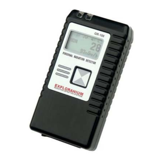
1.0 Overview Introduction The GR-100 is one of the most advanced, yet simple to use, personal radiation monitors deployed in customs, security, military and emergency response applications. It has been designed to provide accurate and reliable measurement of gamma and neutron radiation, trigger visual and audio alarms to warn the operator, and accurately measure exposure Dose Rate over the full spectrum range. - Page 6 GR-100 User's Manual Revision 1.2 1.0 Overview The following figure shows the front and back views of the GR-100 unit. Yellow LED lamp Red LED lamp indicating indicating gamma neutron radiation alarm Cover for battery radiation alarm. Belt clip compartment...
- Page 7 GR-100 User's Manual Revision 1.2 1.0 Overview GR-100 Personal Radiation Monitor Accessories The following figure shows the GR-100 accessories: Belt-mounted carrying pouch 0.25 Micro-Currie CD With GR-100 Cesium Test Monitor Software Source PC interface cable Earphone with Volume Control SAIC/Exploranium – Proprietary...
-
Page 8: Operation
CAUTION: If you remove the battery while the GR-100 is in operation, your data will be lost. Please use the correct power-down sequence before removing the battery to ensure that data will not be lost. -
Page 9: Power On
GR-100 User's Manual Revision 1.2 2.0 Operation Power on To power on the GR-100, make a LONG press with the front panel push button. The STARTUP screen is displayed for approximately 5 seconds: EXPLORANIUM • GR-100 is the instrument model number GR-100 •... -
Page 10: Power Off
GR-100 User's Manual Revision 1.2 2.0 Operation Power off To power the unit OFF press HOLD (press button and hold for about 5 seconds) until the following sequence of displays is seen and the power goes OFF. Note that if you release the button at any point before power-off is completed, the system will take it as a LONG press and it will go back to the SETTING screens. -
Page 11: Dose Rate
The irradiation direction is from the side opposite the display. The Dose Rate is accumulated in the GR-100 memory during operation in Monitoring or Searching mode and stored every hour, or when the unit is powered down. The results can be downloaded to a PC and saved. -
Page 12: Alarms
2.8.2 Alarm Level actions The GR-100 unit is typically worn on a belt. You are alerted to an alarm by an audio beep and/or vibration action, depending on the system settings selection. In alarm condition, you can glance down at the unit and see the flashing LEDs through the transparent windows as a visual reinforcement that an alarm has occurred. -
Page 13: Search Response
GR-100 User's Manual Revision 1.2 2.0 Operation In this case the unit indicates that a GAMMA alarm has occurred. The displayed dose rate is the maximum value measured during the period the alarm message is on the screen. In the alarm condition, the displayed value is obtained from 1 second measurements. -
Page 15: Setting Up The Unit
GR-100 User's Manual Revision 1.2 3.0 Setting up the Unit 3.0 Setting up the Unit To access the unit set-up screens from the MONITOR mode, do a LONG press. The sequence starts with SEARCH. In any of the following screens a SHORT press advances to the next selection and the LONG press activates the selected function or parameter. -
Page 16: Setting Date/Time
VIBRATOR ON / OFF – some users want a covert alarm capability so they want to use the vibrator rather than the beeper. It is recommended placing the GR-100 into the breast pocket in this case. The vibration may not be noticed when the unit is belt mounted. However the vibrator uses a lot of electrical power, thus shortening the battery life. -
Page 17: Long Count Mode
GR-100 User's Manual Revision 1.2 3.0 Setting up the Unit Long Count Mode From the MONITOR display press LONG and than three times SHORT to bring the LONG COUNT setting screen on: LONG COUNT Press LONG to confirm the selection:... -
Page 18: Remote Setup
Remote setup The GR-100 is supplied with an external RS-232 serial cable that plugs into a connector on its base. The other side of the cable is connected to the serial port on a PC running the Monitor 100U Remote Control Software supplied by Exploranium on the CD included with the unit. -
Page 19: Battery Charging
CAUTION: Using any other cable can cause fatal damage to the instrument! Open rubber cover located on the bottom of the GR-100 and insert power cable adapter to the mini-USB jack in the centre. Handle the cover on its left hand side where the earphone connector is located. The right-hand side is fixed to avoid the loss of the cover. -
Page 20: Belt Mounting
If the earphone is used for covert operations with belt mounted leather carrying pouch, connect the plug and insert GR-100 into the leather pouch with the cable on the left-hand side of the unit and close the case. There is space enough for the connector inside the case. It is then easily possible to take out the GR-100 from the case and follow the display during SEARCHING without disconnecting the earphone. -
Page 21: Monitor 100U Pc Software
PC. Note the serial port number. 4. Pull the left-hand side of the rubber cover on the bottom of the GR-100 to gain access to the connectors. The right-hand side of the rubber cover is affixed to the case to prevent accidental loss of the cover. - Page 22 GR-100 has been connected to the PC. If the GR-100 unit is connected to the COM 1 port on the PC, it will start communicating with the PC automatically. If it is connected to a different port, an error message will appear, and you must do the following: 1.
-
Page 23: Testing The Gr-100
GR-100 User's Manual Revision 1.2 4.0 Monitor 100U PC software Testing the GR-100 Clicking the Tests button opens the HW Tests screen for providing a number of equipment tests. The tests can be useful for advanced users or for service technicians. - Page 24 – Reads the real-time clock on the GR-100 and displays the data in the next field. • Send RTC – Reads the real-time clock on the PC and writes it to the GR-100. The data is displayed in the previous field.
- Page 25 4.0 Monitor 100U PC software • LCD – Fills the GR-100 display with test text and allows you to change the contrast of the LCD display with the arrows buttons. You can see the results on the display. TEMP displays the temperature to which the contrast is calculated.
-
Page 26: Setting Up Parameters
GR-100 User's Manual Revision 1.2 4.0 Monitor 100U PC software Get OFF-LINE Data in the Tests window takes the measured data from the equipment memory, automatically recognizes the type of measurement, and displays it in the upper right field of the PC screen. -
Page 27: Vibrator
GR-100 User's Manual Revision 1.2 4.0 Monitor 100U PC software You can change some of the settings to suit your preference or to adapt the instrument to unusual conditions at the site of the measurement. These settings are called User Settings and they can be saved by clicking the Save User Settings button to create a user specific profile. -
Page 28: Dose Units
GR-100 User's Manual Revision 1.2 4.0 Monitor 100U PC software 4.2.4 Dose Units The operator can select his preferred units for the dose measurement in the Dose Units Frame by clicking on the appropriate selection icon. The Gy/hr (Grays per hour) units are used mostly in Europe for radiation dose rate measurements. -
Page 29: Data Retrieval
Set User Settings re-sets the time and date in the unit (Stores the new synchronized clock data). Data retrieval GR-100 stores in its memory all alarm, dose and diagnostic events data acquired during its use. This data can be downloaded to a PC for viewing, printing and saving for subsequent evaluation or electronic distribution. -
Page 30: Alarm Data Retrieval
4.0 Monitor 100U PC software directory where the Monitor 100U program resides. Pressing Clear Alarms/Diag will erase both alarm and diagnostic data from the GR-100 memory. Buttons in the DOSE frame function in the same manner for the dose data. - Page 31 Print and Save to File buttons are enabled. Clicking on the Clear Alarms/Diag button deletes the alarm records from the GR-100 memory. You should be careful not to erase the alarm data until you verified that it was saved correctly under the desired file name.
-
Page 32: Diagnostic Events Retrieval
Clicking on the Read Diagnostics button in the History screen activates the diagnostic events data download from GR-100 to the PC. The individual events that have occurred since the last data erase are displayed in chronological order in the History window. The data appears on the screen as shown below. -
Page 33: Accumulated Dose Data Retrieval
Clicking on the Clear Alarms/Diag button deletes the diagnostics records and also the alarm data from the GR-100 memory. You should be careful not to erase the diagnostics data until you verified that it was saved correctly under the desired file name. The data can be downloaded from the unit and saved repeatedly until it is finally erased. - Page 34 (seconds), Battery Voltage, ICA Battery Capacity Status, and Dose Code, as shown below. The total gamma dose accumulated during the measured period of time is always shown in nSv, regardless which units were selected in the GR-100 prior to starting the measurement. Accumulated...
- Page 35 ENABLED button in the DOSE frame to be able to identify the file in the data directory. Clicking on the Clear Dose button deletes the dose records from the GR-100 memory. You should be careful not to erase the dose data until you verified that it was saved correctly under the desired file name.
-
Page 36: Technical Specifications
GR-100 User's Manual Revision 1.2 5.0 Technical specifications 5.0 Technical specifications Gamma detector and analog processor Detector: Cesium-Iodide Thallium Doped Crystal [CsI(Tl)] 0.3 cu ins ( 5 cm3 ) Volume, 0.5" Dia x 1.5” Long (13 mm Dia x 38 mm Long) with an integral bi-alkali PMT... -
Page 37: Searching
GR-100 User's Manual Revision 1.2 5.0 Technical specifications Searching Response: Variable Tone Buzzer Count Rate on LCD Dose rate on LCD Audio Meter: 0.5 second response time Variable Tone Dosemeter Sample Time: Response: 10 sec Integration Time Constant Energy range: 60 keV - 1.5 MeV... -
Page 38: Data Output
120 hours of monitoring at 25 oC, no backlight, with 1.1 Ah Ni-Cd Charging: Inside GR-100 via external 12 VDC Constant Current Float Charger. Overnight charging, charging status and full charge indicated on display. External power adapter 12 VDC (from 9 to 15 VDC) -
Page 39: Connectors
GR-100 User's Manual Revision 1.2 5.0 Technical specifications 5.11 Connectors Serial Com Channel: USB Mini “B” Jack External Power Supply: USB Mini “B” Jack Mating Connector: Only with Exploranium supplied special cables Earphone: 2.5 mm Mono Jack Mating Connector: 2.5 mm Mono Plug Charger: 2.5 mm Circular Audio Jack, +12 V on the center pin... - Page 40 GR-100 User's Manual Revision 1.2 5.0 Technical specifications Optional: • 110 VAC/12 VDC Power Adapter for battery charging (220 VAC optional) with cable • Reference Source Cesium-137 (0.25 µCi) • Rechargeable Nickel-Cadmium Battery • Rechargeable Nickel-Metal Hydride Battery SAIC/Exploranium – Proprietary...
-
Page 41: Appendix A Error Messages
GR-100 User's Manual Revision 1.2 Appendix A Error messages Appendix A Error messages Display message Problem Action No counts Gamma channel is not working Return to the nearest service center for repair Low counts Unit is situated in a very low background Continue with the measurement.
Need help?
Do you have a question about the GR-100 and is the answer not in the manual?
Questions and answers