Generac Power Systems gp 8000e Owner's Manual
Hide thumbs
Also See for gp 8000e:
- Owner's manual (40 pages) ,
- Diagnostic repair manual (84 pages) ,
- Quick setup manual (12 pages)
Table of Contents
Advertisement
Advertisement
Table of Contents

Related Manuals for Generac Power Systems gp 8000e


Summary of Contents for Generac Power Systems gp 8000e
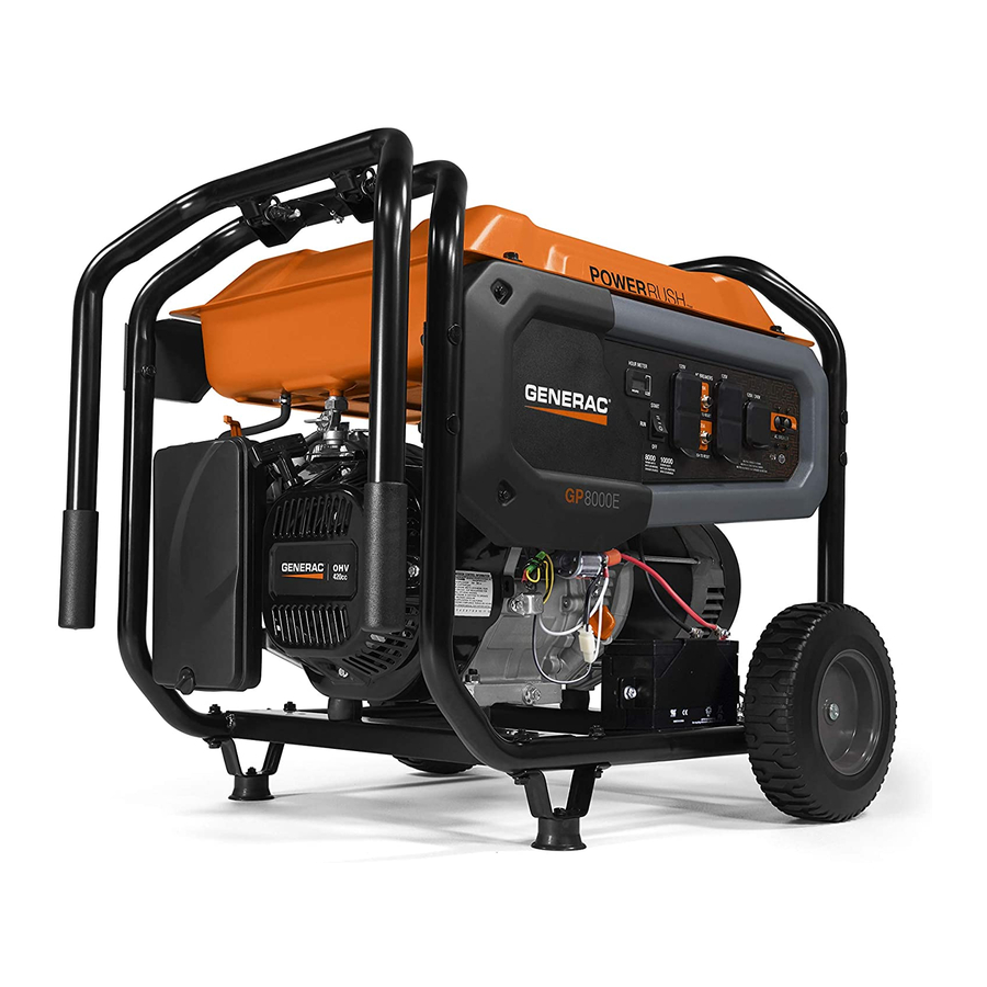
- Page 1 Owner's Manual GP 8000E Portable Generator DEADLY EXHAUST FUMES! ONLY use OUTSIDE far away from windows, doors and vents! NOT INTENDED FOR USE IN CRITICAL LIFE SUPPORT APPLICATIONS. SAVE this Manual. Provide this manual to any operator of the generator.
-
Page 2: Table Of Contents
Table of Contents Introduction ............. 1 Maintenance ............11 Performing Scheduled Maintenance ......11 Read this Manual Thoroughly ......... 1 Maintenance Schedule ..........11 Safety Rules ............1 Product Specifications ..........12 Standards Index .............3 General Recommendations ...........12 Service Air Filter ............13 General Information ..........4 Valve Clearance ............14 General ................14 Unpacking ..............4... -
Page 3: Introduction
Introduction INTRODUCTION Thank you for purchasing this model by Generac Power Systems, Indicates a hazardous situation or action which, if not Inc. This model is a compact, high performance, air-cooled, avoided, could result in minor or moderate injury. engine driven generator designed to supply electrical power to... -
Page 4: Electrical Hazards
Safety Rules ELECTRICAL HAZARDS • Never use the generator or any of its parts as a step. Stepping on the unit can stress and break parts, and may result in • The generator produces dangerously high voltage when in dangerous operating conditions from leaking exhaust gases, operation. -
Page 5: Standards Index
Safety Rules • Never operate the generator if connected electrical devices Unit ID Location overheat, if electrical output is lost, if engine or generator sparks or if flames or smoke are observed while unit is running. • Keep a fire extinguisher near the generator at all times. STANDARDS INDEX 1. -
Page 6: General Information
General Information 1.1 UNPACKING Figure 1 – Wheel & Handle Assembly • Remove all packaging material. 2 X M8 BOLT (LONG) • Remove separate accessory box. 2 X M8 ACORN NUT • Remove the generator from carton. 4 X M8 BOLT (LONG) 1.1.1 ACCESSORIES 2 X COTTER PIN... -
Page 7: Emissions Information
Operation 1.3 EMISSIONS INFORMATION 13. Fuel Gauge – Shows fuel level in tank. 14. Oil Fill – Add oil here. The Environmental Protection Agency (and California Air Resource 15. Recoil Starter – Use to start engine manually. Board for generators certified to CA standards) requires that 16. -
Page 8: Hourmeter
Operation Figure 4 - Generator Controls When the hour meter is in the Flash Alert mode, the maintenance message will always alternate with elapsed time in hours and tenths. The hours will flash four times, then alternate with the maintenance message four times until the meter resets itself. •... -
Page 9: How To Use The Generator
Operation Figure 7 - 120/240 VAC, 30 Amp Receptacle 2.4 HOW TO USE THE GENERATOR See the "To Start the Engine" section for how to safely start and stop the generator and how to connect and disconnect loads. If 2.4.1 GROUNDING THE GENERATOR WHEN USED AS A there are any problems operating the generator, please call the PORTABLE... -
Page 10: Don't Overload The Generator
Operation 2.6 WATTAGE REFERENCE GUIDE 2.4.2 CONNECTING THE GENERATOR TO A BUILDING’S ELECTRICAL SYSTEM Device ........Running Watts *Air Conditioner (12,000 Btu) . -
Page 11: Before Starting The Generator
Operation 2.7 BEFORE STARTING THE GENERATOR Never light a cigarette or smoke when filling the fuel tank. Gasoline is highly FLAMMABLE Prior to operating the generator, engine oil and gasoline will need and its vapors are EXPLOSIVE. Never permit to be added, as follows: smoking, open flames, sparks or heat in the vicinity while handling gasoline. -
Page 12: Starting Electric Start Engines
Operation NOTE: Figure 12 - Choke Position If engine fires, but does not continue to run, move choke lever to FULL CHOKE and repeat starting instructions. CHOKE LEVER IMPORTANT: Do not overload the generator. Also, do not overload LEFT = CHOKE (START) individual panel receptacles. -
Page 13: Stooping The Engine
Maintenance IMPORTANT: Do not overload the generator. Also, do not overload Use battery charger plug to keep the battery charged and ready for individual panel receptacles. These outlets are protected against use. Battery charging should be done in a dry location. overload with push-to-reset-type circuit breakers. -
Page 14: Product Specifications
Maintenance 3.3 PRODUCT SPECIFICATIONS 3.4.1 GENERATOR MAINTENANCE Generator maintenance consists of keeping the unit clean and dry. 3.3.1 GENERATOR SPECIFICATIONS Operate and store the unit in a clean dry environment where it will not be exposed to excessive dust, dirt, moisture or any corrosive Rated Power ................8.0 kW** vapors. -
Page 15: Service Air Filter
Maintenance Use the following instructions to change the oil after the engine Figure 15 - Battery Connections cools down: 1. Clean area around oil drain plug. 2. Remove oil drain plug from engine and oil fill plug to drain oil completely into a suitable container. -
Page 16: Valve Clearance
Maintenance 3.6 VALVE CLEARANCE • Intake — 0.15 ± 0.02mm (cold), (0.006" ± 0.0008" inches) Avoid spray from spark plug hole when • Exhaust — 0.20 ± 0.02mm (cold) (0.008" ± 0.0008" inches) cranking engine. After the first 50 hours of operation, check the valve clearance 6. -
Page 17: Troubleshooting
Troubleshooting 4.1 TROUBLESHOOTING GUIDE PROBLEM CAUSE CORRECTION Engine is running, but no AC output 1. Circuit breaker is open. 1. Reset circuit breaker. is available. 2. Poor connection or defective cord set. 2. Check and repair. 3. Connected device is bad. 3. -
Page 18: Notes
Notes... - Page 19 Notes...
- Page 20 ©2013 Generac Power Systems, Inc. All rights reserved. Specifications are subject to change without notice No reproduction allowed in any form without prior written consent from Generac Power Systems, Inc. Manual Part No. 0K3648 Rev. A (04/15/13) Printed in U.S.A.
Need help?
Do you have a question about the gp 8000e and is the answer not in the manual?
Questions and answers