Table of Contents
Advertisement
Quick Links
GW-BAC1
BACnet Gateway
User Guide
For Interfacing Unitronics PLCs
To Building Automation Systems:
BACnet MS/TP, BACnet/IP, Modbus/TCP.
The information in this document reflects products at the date of printing. Unitronics reserves the right, subject to all applicable laws, at any time, at its sole discretion, and without notice, to discontinue or change
the features, designs, materials and other specifications of its products, and to either permanently or temporarily withdraw any of the forgoing from the market.
All information in this document is provided "as is" without warranty of any kind, either expressed or implied, including but not limited to any implied warranties of merchantability, fitness for a particular purpose, or
non-infringement. Unitronics assumes no responsibility for errors or omissions in the information presented in this document. In no event shall Unitronics be liable for any special, incidental, indirect or
consequential damages of any kind, or any damages whatsoever arising out of or in connection with the use or performance of this information.
The tradenames, trademarks, logos and service marks presented in this document, including their design, are the property of Unitronics (1989) (R"G) Ltd. or other third parties and you are not permitted to use
them without the prior written consent of Unitronics or such third party as may own them
DOC01002-A5 10/14
Advertisement
Table of Contents

Subscribe to Our Youtube Channel
Summary of Contents for Unitronics GW-BAC1
-
Page 1: User Guide
BACnet MS/TP, BACnet/IP, Modbus/TCP. The information in this document reflects products at the date of printing. Unitronics reserves the right, subject to all applicable laws, at any time, at its sole discretion, and without notice, to discontinue or change the features, designs, materials and other specifications of its products, and to either permanently or temporarily withdraw any of the forgoing from the market. - Page 2 Certifications BTL MARK – BACNET TESTING LABORATORY The BTL Mark on GW-BAC1 is a symbol that indicates that a product has passed a series of rigorous tests conducted by an independent laboratory which verifies that the product correctly implements the BACnet features claimed in the listing.
-
Page 3: Table Of Contents
Biasing the Modbus RS-485 Network ......................8 2.2.2 End of Line Termination Switch for the Modbus RS-485 port on the GW-BAC1 .......... 9 BACnet MS/TP Field Devices: Wiring Field Port to RS-485 Network ..............10 Connecting Power to GW-BAC1 ........................11 Creating configuration file and configurating the PLC .................. - Page 4 Figure 2: Power and RS-485 Connections ........................... 7 Figure 3: Modbus RS-485 Biasing Switch on the GW-BAC1 ....................8 Figure 4: Modbus RS-485 End-Of-Line Termination Switch on the GW-BAC1 ..............9 Figure 5: Connection from GW-BAC1 to RS-485 Field Network ..................10 Figure 6: RS-485 EOL Switch .............................
-
Page 5: Introduction
. Configuration for the various protocols is done via Unitronics configuration tool UniBACnet Configurator. Record Identification Data Each GW-BAC1 has a unique serial number located on the underside of the unit. This number should be recorded, as it may be required for technical support. Technical Support For technical support and questions concerning setting up the GW-BAC1 to work with a Unitronics PLC (e.g. -
Page 6: Interfacing Gw-Bac1 To Devices
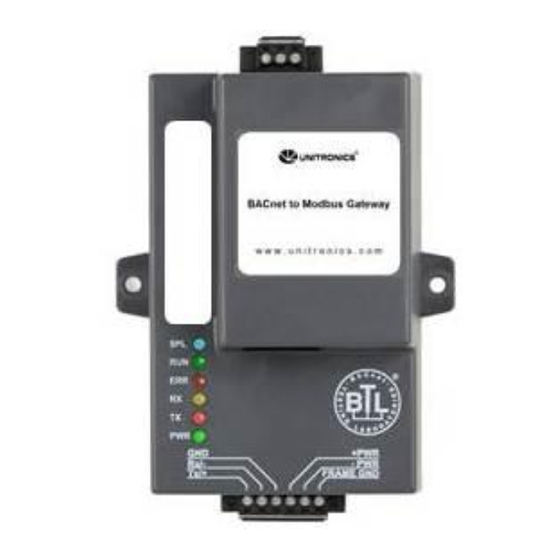
Unitronics’s BACnet Gateway User Guide Page 6 of 28 INTERFACING GW-BAC1 TO DEVICES GW-BAC1 Showing Connection Ports Figure 1: BACnet board Unitronics... -
Page 7: Connecting A Unitronics Plc To The Gw-Bac1 Via Modbus Rs-485
Unitronics’s BACnet Gateway User Guide Page 7 of 28 Connecting a Unitronics PLC to the GW-BAC1 via Modbus RS-485 GW-BAC1 6 Pin Phoenix connector for RS-485 Device The 6 pin Phoenix connector is the same for GW-BAC1. Pins 1 through 3 are for Modbus RS-485 devices. -
Page 8: 2.2.1 Biasing The Modbus Rs-485 Network
The biasing needs to be done on one device. The GW-BAC1 has 530 Ohm resistors that can be used to set the biasing. The GW-BAC1’s default positions from the factory for the Biasing jumpers are OFF. The OFF position is when the 2 RED biasing jumpers straddle the 4 pins closest to the outside of the board of the GW- BAC1. -
Page 9: 2.2.2 End Of Line Termination Switch For The Modbus Rs -485 Port On The Gw-Bac1
On short cabling runs the EOL switch does not to need to be turned ON. If the GW-BAC1 is placed at one of the ends of the trunk, set the blue EOL jumper to the ON position straddling the pins closest to the outside of the board of the GW-BAC1. -
Page 10: Bacnet Ms/Tp Field Devices: Wiring Field Port To Rs-485 Network
BACnet MS/TP Field Devices: Wiring Field Port to RS-485 Network Connect the BACnet MS/TP RS-485 network wires to the 3-pin RS-485 connector on GW-BAC1 as shown below in Error! Reference source not found.. The RS-485 GND (Pin 3) is not typically connected. -
Page 11: Connecting Power To Gw-Bac1
Unitronics’s BACnet Gateway User Guide Page 11 of 28 Connecting Power to GW-BAC1 Apply power to GW-BAC1 as show below in Error! Reference source not found.. Ensure that the power supply used complies with the specifications provided in Appendix B.1. ... -
Page 12: Creating Configuration File And Configurating The Plc
UniBACnet configurator is a tool provided Unitronics that allows the user to create the configuration file for the GW- BAC1 easily. Once created, the configuration file should be downloaded to the GW-BAC1 in order to enable it to communicate with the Unitronics PLC. The UniBACnet configurator can be launched from both the VisiLogic and UniLogic programing applications Tools menu. -
Page 13: Figure 11: Bacnet Connection Ms/Tp Screen
Unitronics’s BACnet Gateway User Guide Page 13 of 28 Configuration file creation steps BACnet Connection: Use this menu for setting up the BACnet Gateway communication parameters. First you must choose the type of BACnet Protocol: MS/TP (Serial) or IP. -
Page 14: Figure 13: Bacnet Nodes Screen
Unitronics’s BACnet Gateway User Guide Page 14 of 28 BACnet Device instance: Here you will add all the BACnet slave devices. Figure 13: BACnet Nodes Screen The Device instance must correspond with the ID given to the device. To assign an ID to the device please follow the configuration manual of the device. -
Page 15: Figure 15: Modbus Connection Rtu Screen
Unitronics’s BACnet Gateway User Guide Page 15 of 28 Note that the read function will let you read and write while write function will only let you write. Read and write block continuous means that the data will be read and write continuously. -
Page 16: Figure 17: Finish Screen
Finish: This window will show the addressing map of the data to be read/write from/to the device -to be use in VisiLogic ladder logic- and will let you export the configuration file that you will download to the GW-BAC1 via the GUI browser. -
Page 17: Figure 18: File Transfer Screen
Unitronics’s BACnet Gateway User Guide Page 17 of 28 h. After setting your PC to be on the same subnet as the GW-BAC1, open a web browser on your PC and enter the IP address of the GW-BAC1; the default address is 192.168.1.24. -
Page 18: Plc Configuration Example
Unitronics’s BACnet Gateway User Guide Page 18 of 28 PLC configuration example. Please note: The following section provides an example of the required configuration using the Vision570 PLC. The configuration required for your specific application may require some changes. VisiLogic includes further examples for BACNet/Modbus RTU and BACnet/Modbus TCP_IP. -
Page 19: Figure 22: Example Of Modbus Configuration
Unitronics’s BACnet Gateway User Guide Page 19 of 28 Figure 22: Example of Modbus configuration Figure 23: Example of MODBUS TCP/IP configurator Figure 24: Example of TCP/IP card and socket initialize Unitronics... -
Page 20: Figure 25: Example Of Tcp/Ip Card And Socket Initialize
Unitronics’s BACnet Gateway User Guide Page 20 of 28 Figure 25: Example of TCP/IP card and socket initialize After the initial configuration, add the proper Modbus commands to read/write data using the addresses table obtained in the finish screen of the UniBACnet Configurator. -
Page 21: Changing The Gw-Bac1 Ip Address
Connect a standard CAT5 Ethernet cable (Straight through or Cross-Over) between the PC and GW-BAC1 The Default IP Address of GW-BAC1 is 192.168.1.24, Subnet Mask is 255.255.255.0. If the PC and GW-BAC1 are on different IP Networks, assign a static IP Address to the PC on the 192.168.1.xxx network ... -
Page 22: Bacnet/Ip: Setting Ip Address For Field Network
If necessary, change the IP Gateway setting in the “Default Gateway” field. Note: If the GW-BAC1 is connected to a router, the IP Gateway of the GW-BAC1 should be set to the IP address of the router that it is connected to. -
Page 23: Appendix A. Troubleshooting
Visual observations of LEDs on GW-BAC1. ( A ppendix A.3) Visual dipswitch settings (using correct baud rate and device instance) Verify IP address setting Verify wiring If the problem still exists, a Diagnostic Capture needs to be taken and sent to Unitronics technical support. ( Appendix A.2) Unitronics... -
Page 24: Appendix A.2. Diagnostic Capture
Diagnostic Capture Once the log in Diagnostic Capture is complete, email it to support@unitronics.com. The Diagnostic Capture will allow us to rapidly diagnose the problem. Ensure that FieldServer Toolbox is loaded on the PC that is currently being used, or download FieldServer- Toolbox.zip at... -
Page 25: Figure 32: Diagnostic Selection
Unitronics’s BACnet Gateway User Guide Page 25 of 28 Select full Diagnostic Figure 32: Diagnostic selection If desired, the default capture period can be changed. Click on Start Diagnostic. Figure 33: Diagnostic tool – start diagnostic Wait for Capture period to finish. Diagnostic Test Complete window will appear. -
Page 26: Figure 34: Diagnostic Tool -Diagnostic Test Complete
Unitronics’s BACnet Gateway User Guide Page 26 of 28 Step 2: Send Log Once the Diagnostic test is complete, a .zip file will be saved on the PC. Figure 34: Diagnostic tool –diagnostic test complete Choose open to launch explorer and have it point directly at the correct folder. Send the Diagnostic zip file to support@fieldserver.com... -
Page 27: Appendix A.3. Led Diagnostics For Modbus Rtu Communications Between Gw-Bac1 And Devices
The SYS ERR LED will go on solid 15 seconds after power up. It will turn off after 5 seconds. A steady red light will indicate there is a system error on GW-BAC1. If this occurs, immediately report the related “system error”... -
Page 28: Appendix B. Reference
Figure 36: Specifications Appendix B.2. Compliance with UL Regulations For UL compliance, the following instructions must be met when operating GW-BAC1. The units shall be powered by listed LPS or Class 2 power supply suited to the expected operating temperature range.
Need help?
Do you have a question about the GW-BAC1 and is the answer not in the manual?
Questions and answers