
Related Manuals for LAVAZZA BLUE LB 3300


Summary of Contents for LAVAZZA BLUE LB 3300
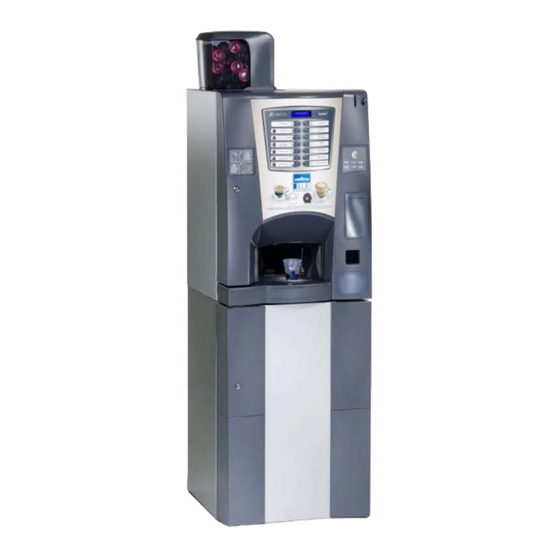
- Page 1 USE AND INSTALLATION MANUAL BLUE LB 3300 Capsules English DOC. NO. H83288 00 EDITION 1 2006 - 10...
- Page 3 DICHIARAZIONE DI CONFORMITA’ DECLARATION OF CONFORMITY DÉCLARATION DE CONFORMITÉ KONFORMITÄTSERKLÄRUNG DECLARACIÓN DE CONFORMIDAD DECLARAÇÃO DE CONFORMIDADE VERKLARING VAN OVEREENSTEMMING INTYG OM ÖVERENSSTÄMMELSE OVERENSSTEMMELSESERKLÆRING YHDENMUKAISUUSTODISTUS Valbrembo, 01/04/2005 Dichiara che la macchina descritta nella targhetta di identificazione, è conforme alle disposizioni legislative delle direttive: 98/37/CE, 89/336, 73/23 CEE e successive modifiche ed integrazioni.
-
Page 5: Table Of Contents
TABLE OF CONTENTS INTRODUCTION PAGE 2 NOTES ON PROGRAMMING PAGE 18 IDENTIFICATION OF THE VENDING MACHINE PAGE 2 POWER ON PAGE 18 IN CASE OF FAILURE PAGE 2 OPERATING MODES PAGE 18 TRANSPORT AND STORAGE PAGE 2 POSITIONING THE VENDING MACHINE PAGE 3 NORMAL OPERATING MODE PAGE 18... -
Page 6: Introduction
Before starting installation and using the machine, it is first Assistenza Tecnica LAVAZZA necessary to carefully read and understand the instruc- Strada Settimo, 410 tions contained in this manual, as they offer important... -
Page 7: Positioning The Vending Machine
POSITIONING THE VENDING MACHINE WARNING FOR SCRAPPING The vending machine is not suitable for outdoor installa- tion. It must be positioned in a dry room where the tempera- The symbol indicates that the machine may not be ture remains between 2°C and 32°C, and not where water disposed of as ordinary waste;... -
Page 8: Power Consumption
- Overheating protection for: CUP DISPENSER Suitable for cups with a rim diameter of 70-71 mm. with a Doser units capacity of approximately 300 cups. Brewer unit ratiomotor Capsule release magnet PAYMENT SYSTEM Pump The machine is supplied with all electrical prearrangement Electric mixers for systems with Executive, BDV and MDB protocol, as - Fuse protection for:... -
Page 9: Variable Combination Lock
CHANGEABLE COMBINATION LOCK Fig. 3 Some machine models are fitted with a changeable com- bination lock. The lock is supplied with one silver colour key, with standard combination, to be used for normal opening and closing. The lock can be customised by means of a kit, available as accessory, permitting changing of the lock combination. -
Page 10: Loading And Cleaning
Chapter 1 LOADING AND CLEANING DOOR SWITCH When opening the door a special switch disconnects the power from the machine electrical system to allow the operations described below, regarding loading and routine cleaning, in full safety. All operations which require the machine to be ener- gised with the door open must be carried out EXCLU- SIVELY by qualified personnel who are aware of the specific risks of such condition. -
Page 11: Controls And Information
CONTROLS AND INFORMATION LOADING CUPS The user controls and information are located on the When loading cups for the first time (I.e. with the cup outside of the door (see Fig. 5). dispenser completely empty) do as follows: The labels with the selection menu and the operating - disconnect the electricity from the machine;... -
Page 12: Loading Coffee
LOADING COFFEE CAPSULES LOADING PRODUCTS AND SUGAR Lift the cover and fill the container with coffee capsules After lifting their cover, fill the single containers with the (see Fig. 7). appropriate products, taking care not to compress them to The capsules can be inserted randomly, as the dispenser prevent packing. -
Page 13: Cleaning The Water Supply Tank
- in order to unscrew the wheels, simply block the disk fitted CLEANING THE WASTE TRAYS on the mixer shaft with a finger; The used capsules trays and dispensing compartment can be removed easily for emptying and cleaning. Fig. 9 The used capsules tray can be removed only with the door open;... -
Page 14: Cleaning The Cup Shift Arm
CLEANING THE CUP SHIFT ARM CLEANING THE SUGAR DISPENSER The cup shift arm must be cleaned periodically by remov- For models with sugar dispensed directly into the cup, the ing it from the machine. In order to remove it, completely sugar dispensing system must be cleaned periodically undo the fastening knurled nut (see Fig. -
Page 15: Cleaning The Capsule Dispenser
To reinstall, do as follows: WEEKLY CLEANING OF BREWER UNIT - check that the handle bearing is outside the area of Every time coffee is refilled, or at least once a week, any interference with the capsule selection disk. Should it be powder residue should be removed from the external parts necessary to line up the device, this can be done manu- of the brewer unit. -
Page 16: Installation
UNPACKING THE VENDING MACHINE Chapter 2 After removing the packing, ensure that the machine is INSTALLATION intact. If in doubt do not use the machine. Installation and the following maintenance operations should be carried out with the machine switched on and No packing elements (i.e. -
Page 17: Overflow Device
This fundamental safety requirement must be duly verified, and if in doubt the system must be carefully tested by qualified technicians. The power supply cable is of the type with a fixed plug. Replacement of the power cable (see Fig. 17) should be Fig. -
Page 18: Installing The Payment System
INSTALLING THE PAYMENT SYSTEM FILLING THE WATER SYSTEM If the air-break device indicates the no-water condition for The machine is sold without payment system, there- more than 10 seconds after the machine has been switched fore the installer of such a system has sole responsi- on, an installation cycle will automatically be started, and bility for any damage to the machine or to things and namely:... -
Page 19: Coffee Unit Operation
COFFEE CAPSULE DISPENSING CYCLE VENDING MACHINE The capsule dispenser allows loading of capsules in a casual manner since it can automatically turn them, straighten them and bring them into the release position. The dispenser is composed of two parts: - the capsule orientation and drive system; - the capsule detection and release system. -
Page 20: Coffee Dispensing Cycle
COFFEE DISPENSING When a coffee-based selection is made a capsule is released into the brewing chamber, that when in stand-by position is vertical (see Fig. 20). The ratiomotor handle rotates 180°, making the brew chamber swing and lowering the upper piston (see Fig. 21). -
Page 21: Checking And Adjusting The Machine Settings
CHECKING AND ADJUSTING STANDARD SETTINGS THE MACHINE SETTINGS The vending machine is supplied with the following set- tings: To get the best results from the product used, the following should be checked: - coffee temperature (at the spout) approx. 85-89°C; - The dose weight of the products. -
Page 22: Notes On Programming
NORMAL OPERATING MODE Notes on programming During the normal operating mode the display shows the message for the user with the prompt to select the drink. The machine electronic control allows or not the use of The function of the buttons can be different according many functions: to the layout and to the choices made during program- All of the available functions are described in the machine... -
Page 23: Surfing Mode
STATISTICS SURFING MODE All data concerning sales and the machine operations is stored in both total counters and relative counters, which The interaction between system and user occurs through can be reset without losing total data. the following components: - Liquid crystal display (LCD) 2 lines of 16 characters. Printing Connect an RS232 serial printer having a Baud rate of - External direct selection push-button panel which takes... -
Page 24: Change Tubes Control
CHANGE TUBES CONTROL FILL> FILL> By accessing the “Tube control” function the change tubes TEST Complete selection can be filled or released manually. Confirm refilling, and the display will indicate “Credit: ——” which is the value of money available in change the tubes;... -
Page 25: Technician Menu
Volumetric counter TECHNICIAN MENU Failed computation of the volumetric counter within a maximum given time. Below is listed a summary explanation of the main func- tions useful for managing the operation of the machine, Boiler grouped by use logic and not necessarily in the order in The machine will lock if after 10 minutes of heating from the which they are displayed in the menu. -
Page 26: Cash
By selecting one of the systems it is possible to control its Coffee out of service functions. The machine is locked upon reaching the number of coffee selections set separately with the “selection counter” func- EXECUTIVE tion. The following payments systems are available for the Executive system: Instant products out of service The machine is locked upon reaching the number of selections... - Page 27 Dispensing buttons Maximum credit This function is used to define the maximum accepted This function enables or not the buttons on the coin credit. mechanism used to release the coins in the change return Maximum change tubes. It is possible to set a limit to the total amount of change Value of “exact amount”...
-
Page 28: Common Functions
COMMON FUNCTIONS COMBINED SELECTIONS A combined selection is intended as the association of two selections, one from the master and one from the slave, to IMMEDIATE CHANGE the same number (80 to 89) sold at a single price. Normally, the amount of a selection is cashed after the Since a numeric keypad is required for setting and control- machine sends the message “Selection successful”. -
Page 29: Selections
SELECTIONS POWDER DOSE The powder dose, expressed in grams, can be set for each The selection menu is composed of various sub-menus selection button and therefore each product assigned to it; which allow setting of the different parameters. the display indicates the name of the product being se- lected. -
Page 30: Vending Machine Parameters
VENDING MACHINE PARAMETERS WASH BUTTON With this function it is possible to enable the operation of This group of functions controls all parameters concerning the mixer wash button. the machine operation. Normally the button is disabled. MAXIMUM NUMBER OF COUNTERS TECH>... -
Page 31: Display
DISPLAY MISCELLANEOUS This group of functions controls all parameters concerning This menu contains some of the functions that are used the display indications. less frequently concerning the machine parameters. TECH> MACHINE PARAMETERS TECH> MACHINE PARAMETERS SET PARAMETERS DISPLAY SET PARAMETERS MISCELLANEOUS LANGUAGE JUG FACILITIES... -
Page 32: Statistics
RESETTING RELATIVE STATISTICS ENERGY SAVING Statistics can be reset either globally (all types of data) or In order to save electric energy when the machine is not in partially for: use, this function is used to switch off the boiler heating. 2 switch-off time bands can be programmed on a weekly - selections basis;... -
Page 33: Test
MDB protocol Audit TEST Aud. 1 Money in the tubes Money present in the change tube that moment DISPENSING With this function it is possible to obtain, with the door open Aud. 2 Money to the tubes and without inserting any money, for each selection dis- Money sent to the change tubes pensing of: - complete selection... -
Page 34: Machine Information
EVADTS CODES MISCELLANEOUS The EVADTS (European Vending Association Data Trans- This menu contains some sub-menus, used less fre- fer System) communication protocol has two codes for quently, which permit control of the functions described identifying the machine and for recognising the data trans- below. -
Page 35: Gsm
UP KEY Up Key -> vending machine The control software can send, via GSM modem, a signal indicating a machine failure or an “ending product” “pre- When confirming this function after inserting the Up Key in alarm”, after dispensing a certain (programmable) number the special port located on the C.P.U. -
Page 36: Maintenance
Chapter 3 MAINTENANCE The integrity of the machine and compliance with the standards of the relevant systems must be checked at least once a year by qualified personnel. Before starting any maintenance operations requiring parts of the unit to be removed, the machine must always be switched off. -
Page 37: Cleaning The Cup Dispenser
CLEANING THE CUP DISPENSER PERIODICAL CLEANING The cup dispenser was designed to be disassembled At least once a year, or more frequently according to the easily for maintenance operations. use of the machine and the quality of the inlet water, the Each single column of the cup stacker and the release ring entire foodstuff circuit system must be cleaned and sani- can be disassembled without using tools. -
Page 38: Printed Board Functions And Indicator Lamps
The control software of the board is installed directly (via PRINTED BOARD FUNCTIONS RS232 or with Up Key on the CPU) in the microprocessor. AND INDICATOR LAMPS - the green LED (2) blinks during normal operation of the board ACTUATION BOARD - the yellow LED (6) indicates the presence of 5 V DC - the red LED (3) glows during the board reset This board (see Fig. -
Page 39: Push-Button Board
PUSH-BUTTON BOARD C.P.U. BOARD This board controls the alphanumeric display, the selec- The C.P.U. (Central Processing Unit) board controls all tion buttons and, located on the internal side, the printer power users set for the maximum configuration, proc- serial port and the service buttons. esses the input signals from the keypad and from the payment system. -
Page 40: Boiler Control Board
BOILER CONTROL BOARD CONFIGURING THE ELECTRONIC BOARDS This board (see Fig. 30) controls the boiler heating ele- The electronic boards are designed to be used in many ment. machine models. In the event of replacement, or when wishing to change the machine performance, it will be necessary to check the configuration of the boards and install the appropriate software. -
Page 41: Hydraulic System
HYDRAULIC SYSTEM 1 - Water inlet solenoid valve 8 - Boiler 2 - Liquid waste container float 9 - Volumetric counter 3 - Mechanical filter 10- Bypass 4 - Air-break 11 - Vibration pump 5 - Coffee capsules canister 12 - Bypass - boiler connection tube 6 - Brewer unit 13 - Dispensing spouts assembly 7 - Solenoid valve assembly... - Page 42 HYDRAULIC SYSTEM Equipped base cabinet Water supply tank and softener unit (optional) 5 - To the machine 1 - Water tank 6 - Coffee grounds bag 2 - Water softener (optional) 7 - Liquid waste container 3 - Water supply pump 4 - Mechanical filter 1006 83288-00 ©...
-
Page 43: Menu Summary
At this point the machine goes into Filler menu mode. Programming menu summary The buttons shown in the figure are used for surfing through the different menus: The machine can function in 3 different operating modes: - Normal vending mode - Filler menu - Technician menu In order to access the programming menus, press the... - Page 44 "Filler Menu" Summary 1 - STATISTICS 1.1 - PRINT STATISTICS 1.1.1 - PARTIAL PRINTOUT 1.1.1.1 - PRINT SEL. COUNT 1.1.1.2 - PRINT BAND COUNT 1.1.1.3 - PRINT DISC COUNT 1.1.1.4 - PRINT FAIL COUNT 1.1.1.5 - PRNT C MECH DATA 1.1.2 - TOTAL PRINTOUT 1.2 - PRINT REL.
- Page 45 "Filler Menu" Summary 1.4 - DIS. REL. STATS 1.4.1 - DIS. SEL. COUNT. 1.4.1.1 - DIS. SIN. COUNT. 1.4.1.2 - DIS. TOT. COUNT. 1.4.1.3 - DIS. SEL. COUNT. 1.4.2 - DIS. BAND COUNT. 1.4.3 - DIS. DISC. SEL. 1.4.4 - DIS. FAIL.COUNT. 1.4.5 - DIS.
- Page 46 "Filler Menu" Summary 3 - TUBES CONTROL 3.1 - FILL TUBES 3.2 - RELEASE TUBES 4 - BOILER TEMPERAT. 5 - TEST 5.1 - COMP. DISPENSING 5.2 - WATER ONLY 5.3 - POWDER ONLY 5.4 - NO ACCESSORIES 5.5 - ACCESSORIES ONLY 6 - GSM 6.1 - RESET PRE-AL CNT 7 - EVADTS...
- Page 47 "Technician Menu" Summary 1 - FAILURES 1.1 - READING FAILURES 1.2 - RESET FAILURES 2 - SET PARAMETERS 2.1 - CASH 2.1.1 - PRICES 2.1.1.1 - SET SIN. PRICES 2.1.1.1.1 - PRICE BAND 0 2.1.1.1.2 - PRICE BAND 1 2.1.1.1.3 - PRICE BAND 2 2.1.1.1.4 - PRICE BAND 3 2.1.1.1.5 - PRICE BAND 4 2.1.1.2 - SET GLOB.
- Page 48 "Technician Menu" Summary 2.2 - SELECTIONS 2.2.1 - SET WATER 2.2.1.1 - WATER DOSES 2.2.1.2 - SET WHIP DOSES 2.2.1.2.1 - SET DOSES 2.2.1.2.2 - SET MODALITY 2.2.1.3 - SOLENOID SETTING 2.2.1.4 - DRIPPING TIME 2.2.2 - SET POWDER 2.2.2.1 - POWDER DOSES 2.2.2.2 - DOSER SETTINGS 2.2.3 - SET ACCESSORIES 2.2.3.1 - ENABLE CUP...
- Page 49 "Technician Menu" Summary 2.4 - DISPLAY 2.4.1 - LANGUAGE 2.4.2 - PROMOT. MESSAGE 2.4.2.1 - EN. PROM. MESS. 2.4.2.2 - SET PROM. MESS. 2.4.3 - CONTRAST CONTROL 2.5 - PRE-SELECTIONS 2.5.1 - NO CUP 2.5.1.1 - SELECTION ENABL. 2.5.1.2 - DOSE VARIATION 2.5.1.3 - PRICE VARIATION 2.5.2 - EXTRA SUGAR 2.5.2.1 - SELECTION ENABL.
- Page 50 "Technician Menu" Summary 2.5.8 - STRENGHT + 2.5.8.1 - SELECTION ENABL. 2.5.8.2 - DOSE VARIATION 2.5.8.3 - PRICE VARIATION 2.5.9 - STRENGHT - 2.5.9.1 - SELECTION ENABL. 2.5.9.2 - DOSE VARIATION 2.5.9.3 - PRICE VARIATION 2.5.A - COFFEE PWD. DOSE 2.5.A.1 - SELECTION ENABL.
- Page 51 "Technician Menu" Summary 2.6 - MISCELLANEOUS 2.6.1 - JUG FACILITIES 2.6.2 - PASSWORD 2.6.2.1 - SET PASSWORD 2.6.2.2 - ENABLE PASSWORD 2.6.2.3 - PWD AZZ. CONTAT. 2.6.2.4 - PWD LAVAGGI 2.6.2.5 - PWD RESET CAPSL 2.6.3 - ENABLE FILL MENU 2.6.4 - ENERGY SAVING 2.6.4.1 - SET ENER.
- Page 52 "Technician Menu" Summary 3.3 - DEL. STATISTICS 3.3.1 - DELETE PARTIAL 3.3.1.1 - DELETE SE. COUNT 3.3.1.2 - DEL. DISC. COUNT 3.3.1.3 - DEL. FAIL. COUNT 3.3.1.4 - DEL. C MECH DATA 3.3.2 - DELETE TOTAL 3.4 - DIS. REL. STATS 3.4.1 - DIS.
- Page 53 "Technician Menu" Summary 3.8 - PRINT REL. STATS 3.8.1 - PARTIAL PRINTOUT 3.8.1.1 - PRINT SEL. COUNT 3.8.1.2 - PRINT BAND COUNT 3.8.1.3 - PRINT DISC COUNT 3.8.1.4 - PRINT FAIL COUNT 3.8.1.5 - PRNT C MECH DATA 3.8.2 - TOTAL PRINTOUT 4 - TEST 4.1 - TEST DISPENSING 4.1.1 - COMP.
- Page 54 "Technician Menu" Summary 5.3 - EVADTS 5.3.1 - PASS.CODE 5.3.2 - SECURITY CODE 5.3.3 - CONNECTION 5.4 - UPKEY 5.4.1 - SETUP MANAGEMENT 5.4.1.1 - UPKEY -> MACHINE 5.4.1.2 - MACHINE -> UPKEY 5.4.1.3 - DELETE 5.4.1.4 - DELETE ALL 5.4.2 - AUDIT MANAGEMENT 5.4.2.1 - MACHINE ->...
-
Page 55: Wiring Diagram
WIRING DIAGRAM LEGEND INITIALS DESCRIPTION INITIALS DESCRIPTION BDV COIN MECH CONNECTOR MF1-.. WHIPPER MOTORS LIQUID WASTE TRAY SWITCH CUP RELEASE MOTOR GENERAL COUNTER MSCB CUP CONTAINER SHIFT MOTOR COFFEE UNIT MOTOR CAM STIRRER RELEASE MOTOR CMSB CUP RELEASE MOTOR CAM TRAY MOVING MOTOR VOLUMETRIC COUNTER CAPSULE DRIVE MOTOR... - Page 60 © by N&W GLOBAL VENDING SpA NOTE...
- Page 61 © by N&W GLOBAL VENDING SpA NOTE...
- Page 62 © by N&W GLOBAL VENDING SpA NOTE...
-
Page 63: Edition 1
The Manufacturer reserves the right to modify, without prior notice, the characteristics of the equipment described in this publication; and further declines to accept any responsibility for any inaccuracies contained in this publication which can be ascribed to printing and/or transcription errors. All instructions, drawings, tables and information contained in this publication are confidential and can neither be repro- duced completely or in part, nor be transmitted to third parties without the written permit of the Manufacturer, who has the sole ownership.
Need help?
Do you have a question about the BLUE LB 3300 and is the answer not in the manual?
Questions and answers