Pioneer CDJ-100S Service Manual
Hide thumbs
Also See for CDJ-100S:
- Operating instructions manual (88 pages) ,
- Service manual (51 pages) ,
- Service manual (26 pages)
Table of Contents
Advertisement
Quick Links
QQ
3 7 63 1515 0
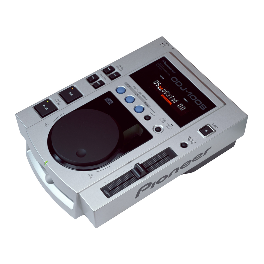
COMPACT DISC PLAYER
CDJ-100S
THIS MANUAL IS APPLICABLE TO THE FOLLOWING MODEL(S) AND TYPE(S).
Model
Type
CDJ-100S
KUC
RL
TE
L 13942296513
WY
CONTENTS
1. SAFETY INFORMATION .................................... 2
2. EXPLODED VIEWS AND PARTS LIST ............. 4
3. SCHEMATIC DIAGRAM ................................... 10
4. PCB CONNECTION DIAGRAM ....................... 24
5. PCB PARTS LIST ............................................. 30
6. ADJUSTMENT .................................................. 33
www
.
PIONEER ELECTRONIC CORPORATION
PIONEER ELECTRONICS SERVICE, INC. P.O. Box 1760, Long Beach, CA 90801-1760, U.S.A.
PIONEER ELECTRONIC (EUROPE) N.V. Haven 1087, Keetberglaan 1, 9120 Melsele, Belgium
PIONEER ELECTRONICS ASIACENTRE PTE. LTD. 501 Orchard Road, #10-00 Wheelock Place, Singapore 238880
PIONEER ELECTRONIC CORPORATION 1998
http://www.xiaoyu163.com
Power Requirement
AC120V
AC110-120V/220-240V
AC220-240V
x
ao
y
i
4-1, Meguro 1-Chome, Meguro-ku, Tokyo 153-8654, Japan
http://www.xiaoyu163.com
2 9
8
The voltage can be converted by the following method.
----------
With the voltage selector
Q Q
3
6 7
1 3
1 5
----------
7. GENERAL INFORMATION .............................. 39
7.1 PARTS ....................................................... 39
7.1.1 IC ....................................................... 39
7.1.2 DISPLAY ........................................... 41
7.2 DIAGNOSIS ................................................ 42
7.2.1 ERROR DISPLAY ............................. 42
7.2.2 DISASSEMBLY ................................. 42
7.3 BLOCK DIAGRAM ...................................... 46
.
9 4
2 8
ORDER NO.
RRV2027
0 5
8
2 9
9 4
2 8
m
....................................................... 47
T-DZY SEPT. 1998 Printed in Japan
9 9
9 9
Advertisement
Table of Contents

Related Manuals for Pioneer CDJ-100S


Summary of Contents for Pioneer CDJ-100S
-
Page 1: Table Of Contents
PIONEER ELECTRONICS SERVICE, INC. P.O. Box 1760, Long Beach, CA 90801-1760, U.S.A. PIONEER ELECTRONIC (EUROPE) N.V. Haven 1087, Keetberglaan 1, 9120 Melsele, Belgium PIONEER ELECTRONICS ASIACENTRE PTE. LTD. 501 Orchard Road, #10-00 Wheelock Place, Singapore 238880 PIONEER ELECTRONIC CORPORATION 1998 T–DZY SEPT. -
Page 2: Safety Information
For the latest information, always consult the current Also test with plug reversed PIONEER Service Manual. A subscription to, or ad- (Using AC adapter u163 ditional copies of, PIONEER Service Manual may be plug as required) obtained at a nominal charge from PIONEER. - Page 3 CDJ-100S 3 7 63 1515 0 IMPORTANT LASER DIODE CHARACTERISTICS THIS PIONEER APPARATUS CONTAINS MAXIMUM OUTPUT POWER: 5 mw LASER OF CLASS 1. WAVELENGTH: 780 – 785 nm SERVICING OPERATION OF THE APPARATUS S H O U L D B E D O N E B Y A S P E C I A L L Y INSTRUCTED PERSON.
-
Page 4: Exploded Views And Parts List
Silica Gel AEN7001 Caution SG DRM1199 Caution Card 220V See Contrast table (2) (2) CONTRAST TABLE CDJ-100S/KUC, RL and WY are constructed the same except for the following: Part No. Symbol and Description Mark Remarks KUC type RL type WY type... - Page 5 CDJ-100S 3 7 63 1515 0 2.2 EXTERIOR (1/2) Refer to "2.3 EXTERIOR (2/2)". RL, WY types Only KUC type Only L 13942296513 Refer to "2.4 SLOT-IN MECHANISM ASSY". u163 http://www.xiaoyu163.com...
- Page 6 DBH1428 Damper DEC2236 Mecha Holder DNH2339 Power Knob DAC1895 (2) CONTRAST TABLE CDJ-100S/KUC, RL and WY are constructed the same except for the following: Part No. Symbol and Description Mark Remarks KUC type RL type WY type MOTHER BOARD Assy...
- Page 7 VBK1070 Caution Label See Contrast table (2) Caution Label HE See Contrast table (2) (2) CONTRAST TABLE CDJ-100S/KUC, RL and WY are constructed the same except for the following: Part No. Symbol and Description Mark Remarks KUC type RL type...
- Page 8 CDJ-100S 3 7 63 1515 0 2.4 SLOT-IN MECHANISM ASSY ∗2 ∗1 Dyefree ME-413A: ZLX-ME413A ∗2 Froil PN-397B: ZLB-PN397B ∗2 ∗1 ∗2 L 13942296513 Refer to " 2.5 SERVO MECHANISM ASSY SECTION". To MOTHER BOARD u163 ASSY CN201 http://www.xiaoyu163.com...
- Page 9 CDJ-100S 3 7 63 1515 0 SLOT-IN MECHANISM ASSY PARTS LIST Mark No. Description Part No. Mark No. Description Part No. Clamper Assy DXA1821 Eject Lever DNK3548 Clamp Spring DBH1374 Loading Lever DNK3406 Guide Spring DBH1375 Cushion A DEC2257...
-
Page 10: Schematic Diagram
CDJ-100S 3 7 63 1515 0 3. SCHEMATIC DIAGRAM Note: When ordering service parts, be sure to refer to "EXPLODED VIEWS AND PARTS LIST" or "PCB PARTS LIST". 3.1 OVERALL CONNECTION DIAGRAM SLOT-IN MECHANISM ASSY (DXA1845) SERVO MECHANISM ASSY-S (DXX2432) - Page 11 CDJ-100S 3 7 63 1515 0 DISPLAY BOARD ASSY (DWG1503) 1/3 to MOTHER BOARD ASSY (DWM2078: KUC type) (DWM2079: RL and WY types) L 13942296513 EARTH LEAD UNIT DDF1010 KUC type Only DIGITAL OUT BOARD ASSY (DWZ1082) TRANS BOARD ASSY...
- Page 12 CDJ-100S 3 7 63 1515 0 3.2 MOTHER BOARD ASSY (1/3) SPINDLE DRIVE SIGNAL ROUTE : RF and Audio Signal Route : Focus Servo Loop : Tracking Servo Loop : LOADING Drive TRACKING DC BOOST FOCUS DC BOOST CN901...
- Page 13 CDJ-100S 3 7 63 1515 0 MOTHER BOARD ASSY (1/3) KUC ONLY (DWM2078: KUC type) (DWM2079: RL and WY types) CN801 DECODER L 13942296513 (T) (T) (F)(F) INVERTER ANALOG SW SERVO CONTROL u163 http://www.xiaoyu163.com...
- Page 14 CDJ-100S 3 7 63 1515 0 ∗ Waveforms of MOTHER BOARD ASSY (1/3) 1 14T-JUMP : After switching to the pause mode, Note : The encircled numbers denote measuring points in the schematic diagram. Press the manual search key.
- Page 15 CDJ-100S 3 7 63 1515 0 Voltages of MOTHER BOARD ASSY (1/3) Set: DJ mode PLAY IC107 IC101 IC103 IC105 IC108 IC102 (TC4W66F) (TC4W53F) (LA6520) (CXA1782CQ) (LA6520) (NJM2068M) Voltage [ V ] Voltage [ V ] Voltage [ V ]...
-
Page 16: 3.3 Mother Board Assy (2/3
CDJ-100S 3 7 63 1515 0 3.3 MOTHER BOARD ASSY (2/3) MOTHER BOARD ASSY (2/3) SIGNAL ROUTE (DWM2078: KUC type) : RF and Audio Signal Route (DWM2079: RL and WY types) IC402 (MB814800–70PJ) Set: DJ MODE PLAY 10 11 12 13 14 Pin No. - Page 17 CDJ-100S 3 7 63 1515 0 IC401 (MN19413A–P) Set: DJ MODE PLAY Pin No. Voltage [ V ] Pin No. Voltage [ V ] Pin No. Voltage [ V ] Pin No. Voltage [ V ] +1.5 +4.9 +4.9 +4.9...
- Page 18 CDJ-100S 3 7 63 1515 0 3.4 MOTHER BOARD ASSY (3/3) Waveforms MOTHER BOARD ASSY (3/3) (DWM2078: KUC type) TP – STA + PLAY MODE (DWM2079: RL and WY types) TP – STA – 5 V/div, 5 µs/div STEPPING DRIVE –...
- Page 19 CDJ-100S 3 7 63 1515 0 IC206 (MPC17A85ZVM) IC701 (PD4977B) Set: DJ MODE PLAY Set: DJ MODE PLAY 10 11 12 13 14 15 16 17 18 19 20 Pin No. Pin No. Voltage [ V ] 0 +4.6 +4.9 0 +1.5 +0.2 +0.4 +0.5 Voltage [ V ] –30.5 to +5...
- Page 20 CDJ-100S 3 7 63 1515 0 3.5 TRANS BOARD ASSY CAUTION: FOR CONTINUED PROTECTION AGAINST RISK OF FIRE. REPLACE ONLY WITH SAME TIME NO. ICP-N25, MFD BY +5V REGULATOR ROHM CO., LTD. FOR IC91. HEAT SINK CN705 L 13942296513 CAUTION: FOR CONTINUED PROTECTION AGAINST RISK OF FIRE.
- Page 21 CDJ-100S 3 7 63 1515 0 NOTE FOR FUSE REPLACEMENT POWER TRANSFORMER CAUTION: FOR CONTINUED PROTECTION DTT1148 AGAINST RISK OF FIRE. REPLACE ONLY WITH SAME TIME AND RATINGS ONLY. AC POWER CORD PDG1015 AC120V 60 Hz POWER TRANSFORMER RL type...
- Page 22 CDJ-100S 3 7 63 1515 0 3.6 DISPLAY BOARD and DIGITAL OUT BOARD ASSEMBLIES FL HOLDER DEB1396 × 2 D FLIP–FLOP L 13942296513 LED ON/OFF CN701 Short: TEST MODE Short: AGING MODE u163 DISPLAY BOARD ASSY (DWG1503) ENCODER http://www.xiaoyu163.com...
- Page 23 CDJ-100S 3 7 63 1515 0 SLIDER VR SWITCHES: S601: TRACK SEARCH (4) S602: SEARCH (1) S603: PLAY/PAUSE (6) S604: TRACK SEARCH (¢) S605: SEARCH (¡) S606: CUE S607: DIGITAL JOG BREAK (JET) S608: MASTER TEMPO S609: DIGITAL JOG BREAK (ZIP)
-
Page 24: Pcb Connection Diagram
CDJ-100S 3 7 63 1515 0 4. PCB CONNECTION DIAGRAM 4.1 SL MECHA BOARD, MOTHER BOARD, TRANS BOARD and DIGITAL OUT BOARD ASSEMBLIES SIDE A MOTHER BOARD ASSY SLOT-IN MECHANISM ASSY Stepping Motor Pickup Assy L 13942296513 Loading Motor Assy... - Page 25 CDJ-100S 3 7 63 1515 0 SIDE A DIGITAL OUT BOARD ASSY AC POWER CORD TRANS BOARD ASSY (DNP1872–C) (DNP1873–C) KUC type Only NOTE FOR PCB DIAGRAMS: 1. Part numbers in PCB diagrams match those in the schematic diagrams.
- Page 26 CDJ-100S 3 7 63 1515 0 SIDE B DIGITAL OUT BOARD ASSY TRANS BOARD ASSY (DNP1873–C) L 13942296513 u163 (DNP1873–C) http://www.xiaoyu163.com...
- Page 27 CDJ-100S 3 7 63 1515 0 SIDE B MOTHER BOARD ASSY (DNP1872–C) L 13942296513 u163 http://www.xiaoyu163.com...
- Page 28 CDJ-100S 3 7 63 1515 0 4.2 DISPLAY BOARD ASSEMBLY SIDE A DISPLAY BOARD ASSY L 13942296513 VR601 u163 (DNP1873–C) CN701 http://www.xiaoyu163.com...
- Page 29 CDJ-100S 3 7 63 1515 0 SIDE B DISPLAY BOARD ASSY L 13942296513 u163 IC602 Q608 Q609 (DNP1873–C) Q610 Q602 Q603 Q601 http://www.xiaoyu163.com...
-
Page 30: Pcb Parts List
CDJ-100S 3 7 63 1515 0 5. PCB PARTS LIST NOTES : ÷ Parts marked by “ NSP ” are generally unavailable because they are not in our Master Spare Parts List. ÷ The mark found on some component parts indicates the importance of the safety factor of the part. - Page 31 CDJ-100S 3 7 63 1515 0 PARTS LIST FOR CDJ-100S/KUC Mark No. Description Part No. Mark No. Description Part No. C157–C159, C161, C162 CKSQYB104K25 MOTHER BOARD ASSY C171, C172, C181, C189 CKSQYB104K25 C193–C195, C202, C206–C210 CKSQYB104K25 SEMICONDUCTORS C212, C218, C314, C319...
- Page 32 CDJ-100S 3 7 63 1515 0 Mark No. Description Part No. Mark No. Description Part No. CEAT471M6R3 DISPLAY BOARD ASSY C12, C23, C24, C591, C83 CKSQYB104K25 C505 CKSQYF103Z50 SEMICONDUCTORS C11, C13–C17, C56 CKSQYF104Z50 IC602 HD74HC175FP C501, C502 CQMA152J50 Q601–Q603 2SC2412K Q608–Q610...
-
Page 33: Adjustment
CDJ-100S 3 7 63 1515 0 6. ADJUSTMENT 6.1 PREPARATIONS 6.1.1 Jigs and Measuring Instruments 8-cm DISC Precise screwdriver screwdriver (With at least about CD TEST DISC screwdriver (small) (medium) 20 minutes recording) 39 kΩ 39 kΩ 0.001 µF 0.0018 µF... - Page 34 CDJ-100S 3 7 63 1515 0 6.2 ADJUSTMENT 6.2.1 How to Start/Cancel Test Mode [ Precautions for Test Mode ] (1) If a soiled or damaged disc is played back and a GFS error is generated, the system may not perform a STOP operation and may run out of control, although muting ON/OFF will be performed.
- Page 35 CDJ-100S 3 7 63 1515 0 6.2.2 Test Mode Key Locations RF Adjustment Mode (Outer circumference feed) Tracking Balance Adjustment Mode (Center circumference feed) Note: The tracking servo is OFF. Fine movement in direction towards the outer circumference of the carriage...
- Page 36 CDJ-100S 3 7 63 1515 0 6.2.4 Check and Adjustment 1. VCO Adjustment Note: Adjustment of VC301 may not be made if the SLOT-IN MECHANISM ASSY is installed. Before adjustment, remove the SLOT-IN MECHANISM ASSY. Test mode DC voltage VC301 2.5±0.2V...
- Page 37 CDJ-100S 3 7 63 1515 0 6.2.4 Check and Adjustment 3. Tracking Error Barance Adjustment Test mode FOCUS servo CLOSE SPDL servo CLOSE TRKG servo OPEN TEST DISC R=35 VR104 PLAY MOTHER BOARD ASSY Oscilloscope DC Mode V: 10mV/div...
- Page 38 CDJ-100S 3 7 63 1515 0 6.2.4 Check and Adjustment 5. Focus Servo Loop Gain Adjustment UPPER UNDER Test mode FOCUS servo CLOSE SPDL servo CLOSE TRKG servo CLOSE WAH Key - ON TEST DISC JUST VR101 PLAY Disc: Center circumference...
-
Page 39: General Information
CDJ-100S 3 7 63 1515 0 7. GENERAL INFORMATION ¶ The information shown in the list is basic information and may 7.1 PARTS not correspond exactly to that shown in the schematic diagrams. 7.1.1 IC PD4977B (IC701: MOTHER BOARD ASSY) - Page 40 CDJ-100S 3 7 63 1515 0 Pin Function No. Name I/O Description No. Name I/O Description GRID 7 FL grid output 7 STCK Stepping motor control output GRID 1 FL grid output 1 XLAT LSI control data latch pulse ––...
-
Page 41: Display
CDJ-100S 3 7 63 1515 0 7.1.2 DISPLAY DEL1031 (V601: DISPLAY BOARD ASSY) FL Tube Pin Assignment Note) F1, F2: Filament G1 to G11: Grid S1 to S15: Anode NP: No pin Pin Connection NL: No Lead Pin No. -
Page 42: Diagnosis
CDJ-100S 3 7 63 1515 0 7.2 DIAGNOSIS 7.2.1 ERROR DISPLAY When the player detects an error during operation, if will immediately stop and display an error code in the display window. Error Code Number Displayed Error Possible Cause = Remedy... - Page 43 CDJ-100S 3 7 63 1515 0 Earth Lead Unit Remove the binder, the card flexible cable (36P FFC/60V), and the top panel part. Disconnect the earth lead unit. Binder Remove the four float springs. Float Spring L 13942296513 Remove the left side damper, slightly raise left side of the slot-in mechanism assy, and disconnect the flexible cables (CN101, CN201, CN202) on the lower side.
- Page 44 CDJ-100S 3 7 63 1515 0 Disengage the hooks on the left and right side (2 each), and DISPLAY BOARD Assy remove the loading base assy. Remove the servo mechanism assy. Remove the jog dial and the slide knob at the top of the body, and then remove the nut (M9) and jog washer.
- Page 45 CDJ-100S 3 7 63 1515 0 Exchange Methods for Rotary Encoder (S614: DSX1051) and Slide Volume (VR601: DCV1009) Slide Volume (VR601: DCV1009) Rotary Encoder (S614: DSX1051) Remove the slide knob from the top of the unit. (Refer to Remove the jog dial, the nut (M9) and the jog washer at the top of "Removal of the DISPLAY BOARD Assy".)
-
Page 46: Block Diagram
CDJ-100S 3 7 63 1515 0 7.3 BLOCK DIAGRAM L 13942296513 u163 http://www.xiaoyu163.com... -
Page 47: U163 . Co
CDJ-100S 3 7 63 1515 0 8. PANEL FACILITIES AND SPECIFICATIONS PANEL FACILITIES Top Panel - MASTER TEMPO button ÷ The master tempo function is turned ON/OFF. ÷ If the button is held depressed for 2 seconds or more, the tempo adjust dial's variable range is changed (±10% or +10% to –16%). -
Page 48: Display Window
CDJ-100S 3 7 63 1515 0 5 MT indicator Display Window Lights when the MASTER TEMPO function is used. 6 A.CUE indicator Lights when the AUTO CUE function is used. 7 Playback address display The elapsed playback time or remaining playback time of the track playing is roughly indicated with the full- scaled bar graph.
Need help?
Do you have a question about the CDJ-100S and is the answer not in the manual?
Questions and answers