Toro Z Master 74941CP Operator's Manual

Toro Z Master 74941CP Operator's Manual

With 48in, 52in or 60in turbo force side discharge mower
Hide thumbs Also See for Z Master 74941CP:
Table of Contents

Advertisement

Form No. 3370-939 Rev A
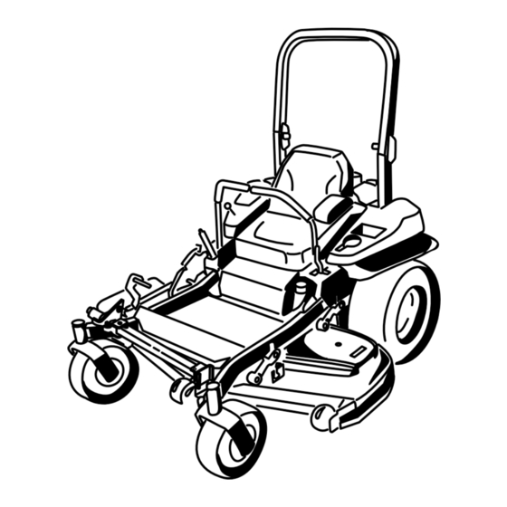
Z Master
®
Riding Mower
with 48in, 52in or 60in TURBO FORCE
®
Side
Discharge Mower
Model No. 74941CP—Serial No. 312000001 and Up
Model No. 74943CP—Serial No. 312000001 and Up
Model No. 74945CP—Serial No. 312000001 and Up
To register your product or download an Operator's Manual or Parts Catalog at no charge, go to www.Toro.com.
Original Instructions (EN)

Advertisement

Table of Contents
loading

Summary of Contents for Toro Z Master 74941CP

  • Page 1 Model No. 74941CP—Serial No. 312000001 and Up Model No. 74943CP—Serial No. 312000001 and Up Model No. 74945CP—Serial No. 312000001 and Up To register your product or download an Operator's Manual or Parts Catalog at no charge, go to www.Toro.com. Original Instructions (EN)
  • Page 2: Introduction

    If you require a spark arrestor, contact your Authorized Toro Dealer. Genuine Toro spark arresters are approved by the USDA Figure 1 Forestry Service. 1. Model and serial number location...
  • Page 3: Table Of Contents

    Contents Servicing the Fuses ..........41 Drive System Maintenance ........41 Checking the Seat Belt ........41 Introduction..............2 Checking the Rollover Protection System Safety ................4 (ROPS) Knobs ..........41 Safe Operating Practices ........4 Adjusting the Tracking........42 Slope Indicator.............
  • Page 4: Safety

    Safety • Use extra care when handling gasoline and other fuels. They are flammable and vapors are explosive. Improper use or maintenance by the operator or owner – Use only an approved container can result in injury. To reduce the potential for injury, –...
  • Page 5: Slope Operation

    Replace all worn or damaged machine. decals. • Be certain that the seat belt can be released quickly • Use only Toro approved attachments. Warranty may in the event of an emergency. be voided if used with unapproved attachments.
  • Page 6: Slope Indicator

    Slope Indicator G011841 Figure 3 This page may be copied for personal use. 1. The maximum slope you can safely operate the machine on is 15 degrees. Use the slope chart to determine the degree of slope of hills before operating. Do not operate this machine on a slope greater than 15 degrees. Fold along the appropriate line to match the recommended slope.
  • Page 7: Safety And Instructional Decals

    Safety and Instructional Decals Safety decals and instructions are easily visible to the operator and are located near any area of potential danger. Replace any decal that is damaged or lost. 68-8340 1-403005 98-5954 103–2076 54-9220 58-6520 1. Grease 105-7798 66-1340...
  • Page 8 110-2067 110-2068 1. Read the Operator's Manual. 107-3069 1. Warning–there is no rollover protection when the roll bar is down. 2. To avoid injury or death from a rollover accident, keep the roll bar in the fully raised and locked position and wear the seat belt.
  • Page 9 116-0211 115-7445 1. Grease pulleys 2. Maintenance interval—50 116-0157 116-0752 1. Locked 2. Unlocked 116-2643 116-0205 116-3303...
  • Page 10 Battery Symbols Some or all of these symbols are on your battery 116-5944 1. Explosion hazard 6. Keep bystandersa safe distance from the battery. 2. No fire, open flame, or 7. Wear eye protection; smoking. explosive gases can cause blindness and other injuries 3.
  • Page 11 120-5898 1. Choke 4. Slow 2. Fast 5. Power take-off (PTO), Blade control switch 120-5897 3. Continuous variable setting 1. Choke 4. Slow 2. Fast 5. Power take-off (PTO), Blade control switch 3. Continuous variable setting 109-7069...
  • Page 12: Product Overview

    Hour Meter Product Overview The hour meter records the number of hours the engine has operated. It operates when the engine is running. Use these times for scheduling regular maintenance (Figure 6). Fuel Gauge The fuel gauge is located with the hour meter and the bars light up when the ignition switch is on (Figure 6).
  • Page 13: Specifications

    Roll Bar - Down 84.8 inches (215.4 enhance and expand its capabilities. Contact your Authorized Service Dealer or Distributor or go to www.Toro.com for a list of all approved attachments Height: and accessories. Roll Bar - Up Roll Bar - Down 70.5 inches (179.1 cm)
  • Page 14: Operation

    Operation DANGER In certain conditions during fueling, static Note: Determine the left and right sides of the electricity can be released causing a spark which machine from the normal operating position. can ignite the gasoline vapors. A fire or explosion from gasoline can burn you and others and can damage property.
  • Page 15: Checking The Engine Oil Level

    Breaking In a New Machine Note: A fuel stabilizer/conditioner is most effective when mixed with fresh gasoline. To minimize the New engines take time to develop full power. Mower chance of varnish deposits in the fuel system, use fuel decks and drive systems have higher friction when new, stabilizer at all times.
  • Page 16: Think Safety First

    DANGER Operating on wet grass or steep slopes can cause sliding and loss of control. Wheels dropping over edges can cause rollovers, which may result in serious injury, death or drowning. There is no rollover protection when the roll bar is down.
  • Page 17: Operating The Parking Brake

    Releasing the Parking Brake CAUTION This machine produces sound levels in excess of 85 dBA at the operators ear and can cause hearing loss through extended periods of exposure. Wear hearing protection when operating this machine. The use of protective equipment for eyes, ears, feet and G016995 head is recommended.
  • Page 18: Operating The Choke

    Always use the fast position when turning on the to start allow a 15 second cool-down period mower deck with the blade control switch (PTO). between attempts. Failure to follow these instructions can burn out the starter motor. Note: Additional starting cycles may be required when starting the engine for the first time after the fuel system has been without fuel completely.
  • Page 19: Starting And Stopping The Engine

    Starting and Stopping the Engine Starting the Engine 1. Raise the ROPS up and lock into place, sit on the seat and fasten the seat belt. 2. Move the motion controls to neutral locked position. G008947 Figure 20 3. Set the parking brake; refer to Setting the Parking Brake.
  • Page 20: The Safety Interlock System

    The Safety Interlock System CAUTION If safety interlock switches are disconnected or damaged the machine could operate unexpectedly causing personal injury. • Do not tamper with the interlock switches. • Check the operation of the interlock switches daily and replace any damaged switches before operating the machine.
  • Page 21: Driving Forward Or Backward

    Using the Motion Control Levers operate as described below, have an Authorized Service Dealer repair the safety system immediately. 1. Sitting on the seat, engage the parking brake and move the blade control switch (PTO) to on. Try starting the engine; the engine should not crank. 2.
  • Page 22: Stopping The Machine

    Stopping the Machine To stop the machine, move the traction control levers to neutral and move to locked position, disengage the power take off (blade control switch (PTO), and turn the ignition key to off. Set the parking brake when you leave the machine; refer to Setting the Parking Brake in Operation.
  • Page 23: Adjusting The Anti-Scalp Rollers

    Adjusting the Height-of-Cut Pin The height-of-cut is adjusted from 1 to 5-1/2 inches (25 to 140 mm) in 1/4 inch (6 mm) increments by relocating the clevis pin into different hole locations. 1. Move the transport lock to the lock position. 2.
  • Page 24: Positioning The Flow Baffle

    1. Disengage the blade control switch (PTO), move the motion control levers to the neutral locked position and set the parking brake. 2. Stop the engine, remove the key, and wait for all moving parts to stop before leaving the operating position.
  • Page 25: Using The Drive Wheel Release Valves

    1. To adjust, move the lever sideways to unlock seat (Figure 32). 2. Slide the seat to the desired position and release lever to lock in position. Changing the Seat Suspension The seat can be adjusted to provide a smooth and comfortable ride.
  • Page 26: Using The Side Discharge

    The drive wheel release valves are located in the back of DANGER each hydraulic drive unit, under the seat. Without a grass deflector, discharge cover, or Note: Make sure the release valves are in the fully complete grass catcher assembly mounted in horizontal position when operating the machine or place, you and others are exposed to blade contact severe damage to the hydraulic system can occur.
  • Page 27: Transporting Machines

    Transporting Machines WARNING Loading a unit onto a trailer or truck increases the Use a heavy-duty trailer or truck to transport the possibility of backward tip-over and could cause machine. Ensure that the trailer or truck has all serious injury or death. necessary brakes, lighting, and marking as required by law.
  • Page 28: Using The Z Stand

    Using the Z Stand® The Z Stand® raises the front end of the machine to allow you to clean the mower and remove the blades. WARNING The machine could fall onto someone and cause serious injury or death. Figure 37 •...
  • Page 29: Operating Tips

    Alternate mowing direction to keep the grass standing down any nicks and sharpen the blades as necessary. If straight. This also helps disperse clippings which a blade is damaged or worn, replace it immediately with enhances decomposition and fertilization. a genuine TORO replacement blade.
  • Page 30: Maintenance

    • Check the torque for wheel lug nuts. Every 500 hours • Adjust the caster pivot bearing. • Check the park brake adjustment. • Change the hydraulic filters and hydraulic oil when using Toro® HYPR-OIL™ 500 hydraulic oil • Check the battery. Monthly •...
  • Page 31: Lubrication

    Lubrication Where to Grease the Mower Service Interval: Every 50 hours—Grease the mower Greasing and Lubrication deck spindles and idler arm. Yearly—Grease the pump belt idler Grease more frequently when operating conditions are arm. extremely dusty or sandy. Yearly—Grease the front caster Grease Type: No.
  • Page 32: Engine Maintenance

    Engine Maintenance WARNING Contact with hot surfaces may cause personal injury. Keep hands, feet, face, clothing and other body parts away the muffler and other hot surfaces. Servicing the Air Cleaner Service Interval: Every 250 hours—Replace the primary air filter. Every 250 hours—Check the Figure 41 secondary air filter.
  • Page 33: Servicing The Engine Oil

    Servicing the Engine Oil Oil Type: Detergent oil (API service SG, SH, SJ, or SL) Oil Capacity: with a filter change, 77 ounces (2.3 L); without a filter change, 70 ounces (2.1 L) Viscosity: See the table below. Figure 43 1.
  • Page 34: Changing The Engine Oil

    Changing the Engine Oil Service Interval: After the first 8 hours Every 100 hours (more often in dirty or dusty conditions) Note: Dispose of the used oil at a recycling center. G008804 1. Park the machine so that the rear is slightly lower than the front to ensure the oil drains completely.
  • Page 35: Changing The Engine Oil Filter

    4. Slowly pour approximately 80% of the specified oil into the filler tube and slowly add the additional oil to bring it to the Full mark (Figure 47). G008804 G008796 Figure 47 5. Start the engine and drive to a flat area. Check the oil level again.
  • Page 36: Servicing The Spark Plug

    Servicing the Spark Plug Service Interval: Every 100 hours Make sure the air gap between the center and side electrodes is correct before installing the spark plug. Use a spark plug wrench for removing and installing the spark plug(s) and a gapping tool/feeler gauge to check and adjust the air gap.
  • Page 37: Check Spark Arrester (If Equipped)

    Checking the Spark Plug Check Spark Arrester (if equipped) Important: Never clean the spark plug(s). Always replace the spark plug(s) when it has: a black Service Interval: Every 50 hours coating, worn electrodes, an oily film, or cracks. If you see light brown or gray on the insulator, the WARNING engine is operating properly.
  • Page 38: Fuel System Maintenance

    Fuel System Note: It is important to reinstall the fuel line hoses and secure with plastic ties the same as they were originally Maintenance installed at the factory to keep the fuel line away from components that could cause fuel line damage. Replacing the Fuel Filter Servicing the Fuel Tank Service Interval: Every 500 hours/Yearly (whichever...
  • Page 39: Electrical System Maintenance

    Electrical System WARNING Maintenance Incorrect battery cable routing could damage the machine and cables causing sparks. Sparks can cause the battery gasses to explode, resulting in Servicing the Battery personal injury. • Always Disconnect the negative (black) battery Service Interval: Monthly cable before disconnecting the positive (red) cable.
  • Page 40: Installing The Battery

    Important: Always keep the battery fully charged (1.265 specific gravity). This is especially important to prevent battery damage when the temperature is below 32°F (0°C). 1. Charge battery for 10 to 15 minutes at 25 to 30 amps or 30 minutes at 10 amps. G008804 2.
  • Page 41: Servicing The Fuses

    Servicing the Fuses Drive System Maintenance The electrical system is protected by fuses. It requires no maintenance, however, if a fuse blows check the component/circuit for a malfunction or short. Checking the Seat Belt 1. The fuses are located on right hand console next to the seat (Figure 56).
  • Page 42: Adjusting The Tracking

    Figure 58 Left control lever shown 1. Control lever 3. Stop plate 2. Bolt Checking the Tire Pressure Figure 57 1. ROPS knob (locked 3. Roll bar in the upright Service Interval: Every 50 hours/Monthly (whichever position) position comes first) 2.
  • Page 43: Checking The Wheel Hub Slotted Nut

    Checking the Wheel Hub nut to align the slot. If required, tighten to the next set of slots. Slotted Nut 7. Install a new cotter pin. Service Interval: After the first 100 hours Note: Do Not use anti-seize on wheel hub. Every 500 hours Adjusting the Caster Pivot See Figure 60 to determine which slotted nut has been...
  • Page 44 Note: Do Not remove the brake pole from the consistently, the shim can be removed to extend the clutch life. field shell/armature. The brake pole has worn to match the armature and needs to continue to match after the shim is removed to ensure proper brake torque.
  • Page 45: Cooling System Maintenance

    Cooling System Maintenance Cleaning the Engine Screen and Engine Oil Cooler Figure 67 Service Interval: Before each use or daily 1. Feeler gauge Remove any build-up of grass, dirt or other debris from the oil cooler (Figure 69). G008804 Figure 68 1.
  • Page 46: Check And Clean The Hydraulic Unit Shrouds

    Figure 70 Figure 71 1. Engine guard 4. Fan housing 1. Hydraulic unit shrouds 2. Engine air intake screen 5. Screw 3. Bolt Check and Clean the Hydraulic Unit Shrouds Service Interval: Before each use or daily 1. Disengage the PTO and set the parking brake. 2.
  • Page 47: Brake Maintenance

    Brake Maintenance Adjusting the Parking Brake Service Interval: After the first 100 hours Every 500 hours thereafter Check to make sure brake is adjusted properly. This procedure must be followed after the first 100 hours or when a brake component has been removed or replaced. 1.
  • Page 48: Belt Maintenance

    Belt Maintenance Inspecting the Belts Service Interval: Every 50 hours Check the belts for squealing when the belt is rotating, blades slipping when cutting grass, frayed belt edges, burn marks and cracks are signs of a worn mower belt. Replace the mower belt if any of these conditions are evident.
  • Page 49: Replacing The Hydraulic Pump Drive Belt

    Figure 75 1. Position the belt cover 3. Ensure the tab is under Figure 76 the metal catch 1. Idler pulley 5. Left hand hydraulic pump 2. Slide belt cover under the pulley side catches 2. Clutch pulley 6. Square hole in idler arm 3.
  • Page 50: Controls System Maintenance

    Controls System Maintenance Adjusting the Control Handle Position There are two height positions for the control levers; high and low. Remove the bolts to adjust the height for the operator. 1. Disengage the PTO, move the motion control levers to the neutral locked position, and set the parking brake.
  • Page 51: Adjusting The Motion Control Damper

    Adjusting the Motion Control not have to be in the seat because of the jumper wire being used. Run engine at full throttle and Damper release brake. The top damper mounting bolt can be adjusted to obtain 6. Run the unit at least 5 minutes with the drive levers a more desired motion control lever resistance.
  • Page 52: Hydraulic System Maintenance

    Hydraulic System Maintenance Servicing the Hydraulic System Hydraulic Oil Type: Toro ® HYPR-OIL ™ ® Figure 81 hydraulic oil or Mobil 1 15W-50. 1. Flanged nut 2. Jam nut Important: Use oil specified or equivalent. Other fluids could cause system damage.
  • Page 53 Mobil 1 oil. Every 500 hours—Change the hydraulic filters and hydraulic oil ® ™ when using Toro HYPR-OIL hydraulic oil To replace the hydraulic oil, the filters need to be removed. Replace both at the same time. 1. Disengage the blade control switch (PTO), move the motion control levers to the neutral locked position and set the parking brake.
  • Page 54: Mower Deck Maintenance

    Mower Deck Maintenance Leveling the Mower Deck Setting Up the Machine Note: Ensure the mower deck is leveled before matching the height-of-cut (HOC). 1. Position mower on a flat surface. 2. Disengage the blade control switch (PTO), move the motion control levers to the neutral locked position and set the parking brake.
  • Page 55 10. Fine-tune the adjustment nut on the front deck lift assembly by turning it (Figure 87). To increase the height, turn the adjustment nut clockwise; to decrease, turn counterclockwise. G017027 Figure 85 1. Deck lift pedal 3. Transport lock 2. Height of cut pin 6.
  • Page 56 Note: In most conditions, the back blade tip should be adjusted 1/4 inch (6.4 mm) higher than the front. 15. On both sides of the deck, measure from the level surface to the back tip of the blade (Position B). The measurement should read 3 1/4 inches (8.3 cm) (Figure 86).
  • Page 57: Servicing The Cutting Blades

    (Figure 91). Measure from a level surface blades as necessary. If a blade is damaged or worn, to the cutting edge, position A, of the blades replace it immediately with a genuine Toro replacement (Figure 91). Note this dimension. blade. For convenient sharpening and replacement, you may want to keep extra blades on hand.
  • Page 58 Installing the Blades performance and continued safety conformance of the machine, use genuine TORO replacement blades. 1. Install the blade onto the spindle shaft (Figure 94). Replacement blades made by other manufacturers may result in non-conformance with safety standards. Important: The curved part of the blade must...
  • Page 59: Removing The Mower Deck

    Removing the Mower Deck Before servicing or removing the mower deck, the spring loaded deck arms must be locked out. WARNING Deck lift arm assemblies have stored energy. Removing the deck with out releasing the stored energy can cause serious injury or death. Do Not attempt to disassemble the deck from the front frame without locking out the stored energy.
  • Page 60: Replacing The Grass Deflector

    g015594 Figure 97 1. Bolt 5. Spring installed 2. Spacer 6. Grass Deflector 3. Locknut 7. J hook end of spring 4. Spring 2. Place spacer and spring onto grass deflector. Place Figure 96 one J end of spring behind deck edge. 1.
  • Page 61: Cleaning

    Cleaning Storage Cleaning and Storage Cleaning Under the Mower 1. Disengage the power take off (blade control switch Service Interval: Before each use or daily (PTO), set the parking brake, and turn the ignition key to Off. Remove the key. 1.
  • Page 62 B. Run the engine to distribute conditioned fuel through the fuel system (5 minutes). C. Stop the engine, allow it to cool, and drain the fuel tank; refer to Servicing the Fuel Tank in the Maintenance Section. D. Restart the engine and run it until it stops. E.
  • Page 63: Troubleshooting

    Troubleshooting Problem Possible Cause Corrective Action Starter does not crank 1. Blade control switch (PTO) is engaged. 1. Move blade control switch (PTO) to disengaged. 2. Parking brake is not on. 2. Set the parking brake. 3. Drive levers are not in neutral lock 3.
  • Page 64 Problem Possible Cause Corrective Action Machine does not drive. 1. By pass valves is not closed tight. 1. Tighten the by pass valves. 2. Pump belt is worn, loose or broken. 2. Change the belt. 3. Pump belt is off a pulley. 3.
  • Page 65: Schematics

    Schematics Wire Diagram (Rev. A)
  • Page 66 Notes:...
  • Page 67 Notes:...
  • Page 68 Instructions for Obtaining Warranty Service The Toro Company and its affiliate, Toro Warranty Company, pursuant to If you think that your Toro Product contains a defect in materials or an agreement between them, jointly promise to the original purchaser workmanship, follow this procedure: to repair the Toro Products listed below if defective in materials or Contact your seller to arrange service of the product.

This manual is also suitable for:

Z master 74943cpZ master 74945cp

Table of Contents