Table of Contents
Advertisement
Quick Links
Register at www.Toro.com.
Original Instructions (EN)
Commercial Walk-Behind Mower
Fixed Deck, Pistol Grip, Hydro Drive with
36in or 48in TURBO FORCE
Model No. 30934—Serial No. 314000001 and Up
Model No. 30938—Serial No. 314000001 and Up
Model No. 39934—Serial No. 314000001 and Up
Model No. 39938—Serial No. 314000001 and Up
Form No. 3379-930 Rev A
®
Cutting Unit
G017540
*3379-930* A
Advertisement
Table of Contents

Related Manuals for Toro 30934


Summary of Contents for Toro 30934
-
Page 1: Cutting Unit
Fixed Deck, Pistol Grip, Hydro Drive with 36in or 48in TURBO FORCE ® Cutting Unit Model No. 30934—Serial No. 314000001 and Up Model No. 30938—Serial No. 314000001 and Up Model No. 39934—Serial No. 314000001 and Up Model No. 39938—Serial No. 314000001 and Up... -
Page 2: Introduction
California to cause cancer, birth defects, product properly and safely. or other reproductive harm. You may contact Toro directly at www.Toro.com for product and accessory information, help finding a dealer, or to register your product. This spark ignition system complies with Canadian ICES-002. -
Page 3: Table Of Contents
Introduction ..............2 if you do not follow the recommended precautions. Safety ................4 Safe Operating Practices........... 4 Toro Mower Safety ..........6 Slope Indicator ............7 Safety and Instructional Decals ......... 8 Figure 2 Product Overview ............11 1. -
Page 4: Safety
Safety Cooling System Maintenance ........35 Cleaning the Air-intake Screen........35 Cleaning the Cooling System........35 Note: The addition of attachments made by other Brake Maintenance ............36 manufacturers that do not meet American National Standards Servicing the Brake ..........36 Institute certification will cause noncompliance of this Belt Maintenance ............37 machine. -
Page 5: Maintenance And Storage
Operation Safe Handling of Fuels • Lightning can cause severe injury or death. If lightning • To avoid personal injury or property damage, use is seen or thunder is heard in the area, do not operate extreme care in handling gasoline. Gasoline is extremely the machine;... -
Page 6: Toro Mower Safety
Use extra care with grass catchers or other attachments. performance of your Toro equipment, count on Toro These can change the stability of the machine. genuine parts. When it comes to reliability, Toro delivers • Keep all movement on slopes slow and gradual. Do not replacement parts designed to the exact engineering make sudden changes in speed or direction. -
Page 7: Slope Indicator
Slope Indicator G011841 Figure 3 This page may be copied for personal use. 1. The maximum slope you can safely operate the machine on is 20 degrees. Use the slope chart to determine the degree of slope of hills before operating. Do not operate this machine on a slope greater than 20 degrees. Fold along the appropriate line to match the recommended slope. -
Page 8: Safety And Instructional Decals
Safety and Instructional Decals Safety decals and instructions are easily visible to the operator and are located near any area of potential danger. Replace any decal that is damaged or lost. 98-0776 1-403005 66-1340 98-3296 For Models with 2 Blade Mower Decks 98-5130 1. - Page 9 103–2076 Battery Symbols Some or all of these symbols are on your battery 1. Explosion hazard 6. Keep bystanders a safe distance from the battery. 2. No fire, open flame, or 7. Wear eye protection; smoking. explosive gases can 104-8569 cause blindness and other injuries 3.
- Page 10 106-2743 Manufacturer's Mark 1. Indicates the blade is identified as a part from the original machine manufacturer. 110-2068 1. Read the Operator's Manual. 110-2067 115-4212 1. Hydraulic oil level 3. Warning—do not touch the hot surface. 2. Read the Operator's Manual.
-
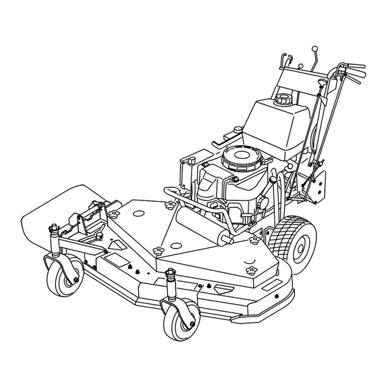
Page 11: Product Overview
Product Overview G017541 Figure 4 1. Side discharge 5. Controls 2. Mower deck 6. Handle Figure 5 3. Recoil-start handle 7. Caster wheel 4. Gas tank 1. Throttle control 6. Handle 2. Speed-control lever 7. Drive lever 3. Ignition switch 8. -
Page 12: Specifications
• Never fill the fuel tank inside an enclosed trailer. its capabilities. Contact your Authorized Service Dealer or Distributor or go to www.Toro.com for a list of all approved • Do not fill the fuel tank completely full. Add attachments and accessories. -
Page 13: Checking The Engine-Oil Level
Using Fuel Stabilizer/Conditioner DANGER Use a fuel stabilizer/conditioner in the machine to keep the In certain conditions during fueling, static fuel fresh during storage of 90 days or less. If you are storing electricity can be released causing a spark which the machine for longer, drain the fuel tank;... -
Page 14: Operating The Parking Brake
Operating the Parking Brake Always set the parking brake when you stop the machine or leave it unattended. Before each use, check the parking brake for proper operation. If the parking brake does not hold securely, adjust it. Refer to Servicing the Parking Brake. -
Page 15: Operating The Neutral Locks
Releasing the Neutral Lock 1. Squeeze the drive levers back until an increase in force is felt. 2. Place your thumbs on the upper part of the locks and move them forward until the pins are in the forward slot (Figure 11). Figure 9 1. -
Page 16: Operating The Mower-Blade-Control Knob (Pto)
Operating the The Safety Interlock System Mower-blade-control Knob CAUTION (PTO) If safety interlock switches are disconnected or damaged the machine could operate unexpectedly The blade-control knob (PTO) is used in conjunction with causing personal injury. the Operator Presence Control (OPC) levers to engage and disengage the mower blades. -
Page 17: Driving The Machine Forward And Backward
Driving Backward 4. Push the blade-control knob down to off. 5. With engine running, hold down the OPC levers. From neutral, slowly squeeze the drive levers to move Pull the blade-control knob (PTO) up. The drive belt rearward (Figure 13). should engage and the mower blades should begin rotating. -
Page 18: Adjusting The Flow Baffle
Positioning the Flow Baffle Note: Rotate the bypass valves a maximum of 2 turns so the valve does not come out of the body causing The following figures are only recommendations for use. fluid to run out. Adjustments will vary by grass type, moisture content, and Important: Do not start or operate the machine height of grass. -
Page 19: Transporting Machines
Position C Side Discharging or Mulching the Grass This is the full open position. The suggested use for this position is as follows (Figure 18). This mower has a hinged grass deflector that disperses • Use in tall, dense grass mowing conditions. clippings to the side and down toward the turf. -
Page 20: Adjusting The Caster Position
Figure 20 1. Top axle bolt 2. Lower axle bolt 7. Raise or lower the mounting bracket so that you can install the 2 axle adjustment bolts in the desired hole location (Figure 20). Note: Use a tapered punch to help align the holes. 8. -
Page 21: Adjusting The Handle Height
Adjusting the Handle Height The handle position can be adjusted to match the operator's height preference. 1. Remove the hairpin cotter pins and clevis pins from the drive levers and neutral locks (Figure 22). Figure 23 1. Control rod fitting 6. -
Page 22: Height-Of-Cut Chart
Height-of-cut Chart Number of spacers Number of 1/4 inch blade spacers below spindle below caster 13 mm 5 mm (1/2 inch ) (3/16 inch) Axle position 26 mm 32 mm 38 mm 45 mm 51 mm (1 inch) (1-1/4 inch) (1-1/2 inch) (1-3/4 inch) (2 inch) -
Page 23: Maintenance
Maintenance Note: Determine the left and right sides of the machine from the normal operating position. Recommended Maintenance Schedule(s) Maintenance Service Maintenance Procedure Interval • Change the engine oil. • Check the mower belt tension. After the first 8 hours •... -
Page 24: Lubrication
Lubrication Greasing the Pump Control and the Bell Crank Use Figure 24 for locating the grease points on the machine. Service Interval: Every 50 hours—Grease the pump drive Grease Type: #2 general-purpose lithium-based or idler pivot. molybdenum-based grease Every 50 hours—Grease the pump control. Lubricating the Machine Every 100 hours—Grease the blade engagement bellcrank. -
Page 25: Engine Maintenance
Engine Maintenance Cleaning the Foam Air-cleaner Element 1. Wash the foam element in liquid soap and warm water. When the element is clean, rinse it thoroughly. Servicing the Air Cleaner 2. Dry the element by squeezing it in a clean cloth. Important: Replace the foam element if it is torn Service Interval/Specification or worn. -
Page 26: Changing The Engine Oil
Changing the Engine Oil 1. Park the machine so that the drain side is slightly lower than the opposite side to ensure that the oil drains completely. 2. Disengage the PTO and set the parking brake. 3. Stop the engine, remove the key, and wait for all moving parts to stop before leaving the operating position. -
Page 27: Servicing The Spark Plugs
Figure 29 1. Oil filter 2. Adapter Figure 30 1. Spark-plug wire/spark plug 3. Apply a thin coat of new oil to the rubber gasket on the replacement filter (Figure 29). 4. Clean around the spark plugs to prevent dirt from 4. -
Page 28: Fuel System Maintenance
Installing the Spark Plugs Fuel System 1. Install the spark plugs and the metal washer. Ensure Maintenance that the air gap is set correctly. 2. Tighten the spark plugs to 22 N-m (16 ft-lb). Servicing the Fuel Tank 3. Connect the wires to the spark plugs (Figure 31). DANGER In certain conditions, gasoline is extremely flammable and highly explosive. -
Page 29: Servicing The Fuel Filter
Servicing the Fuel Filter Service Interval: Every 200 hours/Yearly (whichever comes first) Replacing the Fuel Filter Never install a dirty filter if it is removed from the fuel line. Note: Note how the fuel filter is installed in order to install the new filter correctly. -
Page 30: Drive System Maintenance
Drive System 8. If needed, adjust the switch location to create the 8 mm (5/16 inch) space (Figure 36). Maintenance Perform the following linkage adjustments when the machine needs maintenance. Perform the steps Adjust the Speed Control Linkage through Adjusting the Tracking. If any adjustments are needed, do them in the order that they are listed. -
Page 31: Adjusting The Hydro Control Linkages
2. Stop the engine and wait for all moving parts to stop before leaving the operating position. 3. Raise the rear of the machine onto jack stands to raise the drive wheels off the ground. 4. Disengage the parking brake. 5. - Page 32 Note: The OPC levers must be held down whenever 7. Place the speed-control lever in the neutral position. the speed-control lever is out of the neutral position or the engine will stop. WARNING 14. Make sure that the speed–control lever is in the neutral Electrical system will not perform proper position and the tire does not rotate.
-
Page 33: Adjusting The Control Rod
Adjusting the Control Rod 4. Turn the knob clockwise 1/4 of a turn at a time. Then move the speed-control forward and back to neutral. 1. Adjust the rod length by releasing the drive lever and Repeat this until the right wheel stops rotating forward removing the hairpin cotter pin and clevis pin. -
Page 34: Adjusting The Tracking
Adjusting the Tracking 1. Remove the machine from any jack stands. 2. Check the rear tire pressure. Refer to Checking the Tire Pressure. 3. Run the machine and observe the tracking on a level, smooth, hard surface such as concrete or asphalt. 4. -
Page 35: Checking The Tire Pressure
Cooling System 3. For a heavier drive setting, relocate the spring anchor links to either the medium or heavy duty positions Maintenance (Figure 45). The spring anchor links are attached to the upper rear corner of the hydro drive shields on the left and right sides of the machine. -
Page 36: Brake Maintenance
Brake Maintenance yoke counterclockwise out of the yoke out to loosen the parking brake (Figure 48). Note: There should be approximately 6 mm (1/4 inch) Servicing the Brake clearance between the tire and the flat bar with the parking brake in the released position (Figure 48). Before each use, check the parking brake for proper operation. -
Page 37: Belt Maintenance
Belt Maintenance 10. Remove the hairpin cotter pin and the clevis pin from the bell crank. 11. Rotate the clevis clockwise on the rod to increase the Checking the Belts clearance; rotate it counterclockwise to decrease it (Figure 49). Service Interval: Every 50 hours/Monthly (whichever comes first)—Check the belts. -
Page 38: Adjusting The Mower Belt Tension
1. Disengage the blade-control (PTO) lever and set the parking brakes. 2. Stop the engine and wait for all moving parts to stop before leaving the operating position. 3. Loosen the locknut on the turnbuckle (Figure 52). 4. Rotate the turnbuckle toward the rear of the mower to increase the tension on the belt. - Page 39 1. Disengage the blade-control (PTO) lever and set the parking brakes. 2. Stop the engine and wait for all moving parts to stop before leaving the operating position. 3. Loosen the locknut on the turnbuckle (Figure 54). 4. Rotate the turnbuckle toward the rear of the mower to increase the tension on the belt.
- Page 40 Note: The distance between the belt guide and the mower belt should be 19 mm (3/4 inch) when you engage the mower belt (Figure 56). Adjust the mower belt as necessary. The disengaged belt should not drag or fall off the pulley when the guides and belt tension are properly adjusted.
-
Page 41: Hydraulic System Maintenance
Every 25 hours 2. Stop the engine and wait for all moving parts to stop before leaving the operating position. Hydraulic Oil Type: Toro® HYPR-OIL™ 500 hydraulic oil or Mobil® 1 15W-50 3. Disengage the blade-control lever (PTO). Make sure that the assist arm is against the front assist arm stop. -
Page 42: Bleeding The Hydraulic System
8. Recheck the fluid level while the fluid is warm. If required, add fluid to the reservoir until it reaches the hot level of the baffle. Note: The fluid level should be to the top of the hot level of the baffle, when the fluid is warm (Figure 60). 9. -
Page 43: Checking The Hydraulic Hoses
Checking the Hydraulic Hoses 2. Stop the engine and wait for all moving parts to stop before leaving the operating position. Service Interval: Every 100 hours 3. Raise the rear of the machine up onto jack stands high Check hydraulic hoses for leaks, loose fittings, kinked lines, enough to raise the drive wheels off the ground. -
Page 44: Mower Deck Maintenance
Mower Deck Inspecting the Blades Service Interval: Before each use or daily Maintenance 1. Inspect the cutting edges (Figure 63). If the edges are not sharp or have nicks, remove and sharpen the blades. Refer to Sharpening the Blades. Servicing the Cutting Blades To ensure a superior quality of cut, keep the blades sharp. -
Page 45: Removing The Blades
(Figure 68). Maintain the original angle. The Toro replacement blades. Replacement blades made by other blade retains its balance if the same amount of material manufacturers may result in non-conformance with safety is removed from both cutting edges. -
Page 46: Adjusting The Blade Brake
Figure 69 1. Blade 2. Balancer Installing the Blades 1. Install the curved washer and then the blade onto the bolt. Select the proper number of spacer(s) for the height of cut, and slide the bolt into the spindle (Figure 67). -
Page 47: Storage
Storage Cleaning and Storage 1. Disengage the power take-off (PTO), set the parking brake, and turn the ignition key to the off position. Remove the key. 2. Remove grass clippings, dirt, and grime from the external parts of the entire machine, especially the engine. - Page 48 in a memorable place. Cover the machine to protect it and keep it clean.
-
Page 49: Troubleshooting
Troubleshooting Problem Possible Cause Corrective Action The engine will not start, starts hard, or 1. The fuel tank is empty. 1. Fill the fuel tank with gasoline. fails to keep running. 2. The fuel-shutoff valve is closed. 2. Open the fuel-shutoff valve. 3. - Page 50 Problem Possible Cause Corrective Action The blades do not rotate. 1. The mower deck belt is worn or loose. 1. Check the belt tension. 2. The mower deck belt is broken. 2. Install a new deck belt. 3. The mower deck belt is off pulley. 3.
-
Page 51: Schematics
Schematics Electrical Schematic (Rev. -) Hydraulic Schematic (Rev. -) - Page 52 Customers who have purchased Toro products outside the United States or Canada should contact their Toro Distributor (Dealer) to obtain guarantee policies for your country, province, or state. If for any reason you are dissatisfied with your Distributor's service or have difficulty obtaining guarantee information, contact the Toro importer. If all other remedies fail, you may contact us at Toro Warranty Company.
Need help?
Do you have a question about the 30934 and is the answer not in the manual?
Questions and answers