Table of Contents
Advertisement
Quick Links
Advertisement
Table of Contents

Related Manuals for HELIX HLT2500


Summary of Contents for HELIX HLT2500
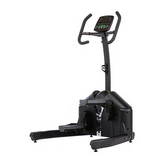
- Page 1 Aerobic Lateral Trainer...
-
Page 2: Important Safety Information
IMPORTANT: THE MAXIMUM RECOMMENDED WEIGHT CAPACITY FOR YOUR Helix is 300lbs/ 136kg per user. WARNING: Before commencing with any exercise program, please consult your family physician. If at any time during exercise you feel faint, dizzy or experience pain, stop and consult your family physician. - Page 3 If you find that you are missing parts or the bag for a step is missing, please IMPORTANT!!! THE MAXIMUM RECO contact Helix or your dealer to receive 130Kg (286 lbs.) per user. those items. You can refer to the parts by the “step number” for ease of...
- Page 4 Item# Part Description Left and Right Frame Legs Transport Wheel Assembly Pedal Frames and Covers Main Frame Rubber Gasket for Upright Electronic Console Display Center Upright Post Handlebars Left and Right Console Mounting Plate Water Bottle Holder Bolts Pedal Frame Bolts Computer Console Mounting Bolts Center Upright Mounting Bolts Handlebar Bolts...
-
Page 5: Before You Begin
PAGE 5 IMPORTANT: Read all instructions carefully. Assemble the Helix in accordance with the steps in the manual. All tools required for assembly are included with your Helix. Lay out all parts on the floor. Make sure that you have all the parts listed below before beginning assembly. In case of a discrepancy, please contact our Customer Service Department at the email address or customer service number listed on the back page of this Owner’s Manual. -
Page 6: Unpacking & Assembly
Step 3: Attach the End Caps (with HELIX branding ) to the left and right stabilizers. The branded end caps install on the end farthest from the attaching bolt holes. Attach Rear End caps (no branding) to the left and right stabilizers at the end closes to the attaching bolt holes. They are front and rear specific but not left... - Page 7 PAGE 7 Step 4: Insert the Stabilizer Leg assembly bolts into the legs and secure as shown Figure Tighten these bolts firmly. If the Helix is not stable on the floor, the level can be adjusted with any of the leveling feet at each corner of the Helix...
- Page 8 AssembLy / PeDALs PAGE 8 Step 4: The pedals have two bolts pre-installed and require two Hex head bolts from the Step 4 hardware pack. 2 bolts are pre-installed Holding the frame up to the crank arm, loosely install the lower left and lower right hex head bolts through the round pedal flange into the identical flange on the crank assembly.
- Page 9 At the base of the main upright connect the wiring harness coming from the upright to the wiring harness coming from the main body of the Helix Figure #3. After these are connected, tuck the wire and connection into the upright and be sure the wire is clear of the large gears in the body.
-
Page 10: Handle Bars Installation
AssembLy - HAnDLe bARs PAGE 10 HANDLE BARS INSTALLATION : Step 8: For ease of installation, first install two handlebar bolts temporarily one in each of the holes show above the arrow in Figure #1 above. Step 9: Then holding one handlebar in your hand, carefully feed the pulse sensor wire into the upright and out of the hole at the top of the upright Figure #3. Once the wire is out of the top of the upright, remove one of the temporary bolts and use it to secure the handlebar in place while you prepare to install the remaining 3 bolts into the handlebar on that side. -
Page 11: Computer Installation
AssembLy - COnsOLe / COmPuTeR PAGE 11 Step 10: Console Bracket Installation: Feed three (3) wires through the center hole of the console bracket as shown in Figure #1 above. Once the three wires are completely through, install the four (4) bolts securing the console bracket to the upright (Figure #2). -
Page 12: Water Bottle Holder Installation
Step 13: NOTE: This part may be factory pre-installed Raise up one side of the Helix onto a box or one of the styrofoam blocks from the packaging. Install the transport wheel as shown. Make note in (Figure #1) above the location of the longer bolt and the shorter bolt. - Page 13 Sleep. There will be no computer display in that mode. Display: The computer on the Helix has two display screens. One is the Data Display and the other the Dot Matrix Display. The Data display windows can display the following information:...
-
Page 14: Dot Matrix Display
These program keys can be used to directly choose a program. Alternatively, the user can scroll the programs with the up or down key. When the Helix computer first starts, this scrolling message will read across the Data Display Screen. “CHOOSE PROGRAM OR QUICK START” Pressing the QUICK START key in the center of the console, will begin the workout immediately... - Page 15 COmPuTeR OPeRATIng InsTRuCTIOns PAGE 15 Quick Start: Program Selection: When the computer first starts, the user can choose one of eight program buttons on either side of the large dot matrix display; Manual, Random, Interval, Heart Rate Control, valley, Rolling, Mountain or Olympian. Choose the program by pushing the button beside the program name or by scrolling through the choices with the up or down key. When the program shown is the program desired, press the Enter key.
- Page 16 COmPuTeR OPeRATIng InsTRuCTIOns PAGE 16 Heart Rate Control Program If the user chooses the Heart Rate Control program, the user will again be asked to enter their weight as above. The user will then be asked to set the desired heart rate. The message will read “SET HRC 80”.
-
Page 17: Summary Mode
COmPuTeR OPeRATIng InsTRuCTIOns PAGE 17 Cool Down: At any time during the workout, press the CLEAR key to proceed directly into the Cool Down mode. Also, at the end of the workout time, the computer will automatically proceed into the Cool Down Mode. -
Page 18: Control Keys
COmPuTeR OPeRATIng InsTRuCTIOns PAGE 18 Heart Rate Display Heart rate will be display by either holding both hands on the hand grip sensors or by wearing a Polar compatible Heart rate chest strap (not included). When holding the hand grip sensors or when wearing the chest strap, the dot will flash in the PULSE field. If “P” is showing in the Pulse field, please either adjust your grip or adjust the Polar Chest strap to improve the connection. -
Page 19: Program Keys
COmPuTeR OPeRATIng InsTRuCTIOns PAGE 19 PROGRAM KEYS There are eight (8) program keys on the left and right side of the Large Dot Matrix display. These program keys can be used directly to choose a program instead of scrolling up and down through the program list. - Page 20 If you cannot reach the dealer, please feel free to contact Helixco at 888-Helixco or by email to service@helixco.com Distributed under license from Kriptonite Corp by Helix Company, a division of M & S Distribution, Inc, 572 Freeport Street, Unit A, Boston, MA 02122 This product is patented in the US and other International Patents and patents pending.
Need help?
Do you have a question about the HLT2500 and is the answer not in the manual?
Questions and answers