KTM 450 EXC Owner's Manual
Hide thumbs
Also See for 450 EXC:
- Owner's manual (136 pages) ,
- Setup instructions (31 pages) ,
- Owner's manual (70 pages)
Table of Contents
Advertisement
Advertisement
Table of Contents

Related Manuals for KTM 450 EXC


Summary of Contents for KTM 450 EXC
- Page 1 OWNER'S MANUAL 2010 450 EXC USA 530 EXC USA ART. NO. 3211485en...
- Page 3 KTM accepts no liability for delivery options, deviations from illustrations and descriptions, as well as misprints and other errors.
-
Page 4: Table Of Contents
LOCATION OF SERIAL NUMBERS ........12 Important maintenance work to be carried out by an Chassis number............. 12 authorized KTM workshop. (as additional order)....32 Type label..............12 Important checks and maintenance work to be carried Key number ..............12 out by the rider. - Page 5 TECHNICAL DATA - ENGINE TIGHTENING TORQUES..88 Changing the rear brake linings ........59 TECHNICAL DATA - CARBURETOR........90 Removing the front wheel .......... 60 450 EXC USA ............... 90 Installing the front wheel ........... 61 530 EXC USA ............... 90 Removing rear wheel ..........61 TECHNICAL DATA - CHASSIS ..........
-
Page 6: Means Of Representation
All work marked with this symbol requires specialist knowledge and technical understanding. In the interest of your own safety, have these jobs done in an authorized KTM workshop! There, your motorcycle will be serviced optimally by specially trained experts using the specialist tools required. -
Page 7: Important Notes
Warranty The work prescribed in the service schedule must be carried out in an authorized KTM workshop and confirmed in the customer's ser- vice record, since otherwise no warranty claims will be recognized. No warranty claims can be considered for damage resulting from manipulations and/or alterations to the vehicle. -
Page 8: Overview Of Labels
IMPORTANT NOTES Environment Offroad motorcycling is a wonderful sport and we naturally hope that you will be able to enjoy it to the fullest. However, it is a poten- tial problem for the environment and can lead to conflicts with other persons. But if you use your motorcycle responsibly, you can ensure that such problems and conflicts do not have to occur. - Page 9 IMPORTANT NOTES 500251-01 Type label for the USA Fuel evaporative system information 500254-01 Chain tension information 500255-01 Information on putting into operation 700210-01 500252-01 Emission control information...
- Page 10 Hotline. Noise emission warranty KTM Sportmotorcycle AG warrants that this exhaust system, at the time of sale, meets all applicable U.S. EPA Federal noise stan- dards. This warranty extends to the first person who buys this exhaust system for purposes other than resale, and to all subsequent buyers.
- Page 11 Consumer rights Warranty claims should be submitted to a KTM workshop. If you are not satisfied, please contact: KTM North America, Inc., Customer Support, 1119 Milan Ave., Amherst, OH 44001, USA Telefon: (440) 985–3553...
-
Page 12: View Of Vehicle
VIEW OF VEHICLE View of the vehicle from the left front (example) 300399-10 Side stand Shift lever Chain guide Fuel tap Air filter box lid Clutch lever Light switch, headlight flasher button, flasher switch, horn button Hand brake lever... -
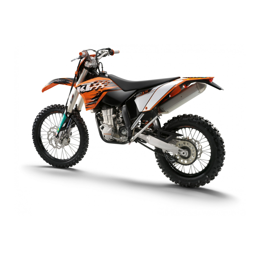
Page 13: View Of The Vehicle From The Right Rear (Example)
VIEW OF VEHICLE View of the vehicle from the right rear (example) 300398-10 Level viewer for brake fluid, rear Fork compression adjustment Foot brake pedal Kickstarter Horn Ignition switch Fork rebound adjustment Filler cap Shock absorber compression adjustment Shock absorber rebound adjustment... -
Page 14: Location Of Serial Numbers
LOCATION OF SERIAL NUMBERS Chassis number The chassis number is stamped on the steering head on the right. 500127-10 Type label The type label USA is fixed to the front of the steering head. 300402-10 The type label Canada is fixed to the front of the front pipe. -
Page 15: Fork Part Number
LOCATION OF SERIAL NUMBERS Fork part number The fork part number is stamped on the inner side of the fork stub. 500082-10 Shock absorber part number The shock absorber part number is stamped on the top of the shock absorber above ... -
Page 16: Controls
CONTROLS Clutch lever The clutch lever is fitted on the left side of the handlebar. The clutch is hydraulically operated and self-adjusting. 500133-10 Hand brake lever Hand brake lever is located on the right side of the handlebar. The hand brake lever is used to activate the front brake. -
Page 17: Light Switch
CONTROLS Light switch Light switch is fitted on the left side of the handlebar. Possible states Low beam on – Light switch is turned downward. In this position, the low beam and tail light are switched on. High beam on – Light switch is turned upward. In this position, the high beam and tail light are switched on. -
Page 18: Speedometer
CONTROLS Speedometer 5.11 – Press the key to change the display mode or change to one of the setup menus. – Press the button to control different functions. – Press the button to control different functions. Info In its condition at delivery, the display mode SPEED/H and SPEED/ODO is acti- vated. -
Page 19: Setting The Clock
CONTROLS – Press the button for 3 - 5 seconds. The settings are saved and the Setup menu closed. Info If no button is pressed for 20 seconds, or if no impulse comes from the wheel speed sensor, the settings are automatically saved and the Setup menu closed. -
Page 20: Querying The Lap Time
CONTROLS – Press the button for 3 - 5 seconds. The settings are saved and the Setup menu closed. Info If no button is pressed for 20 seconds, or if no impulse comes from the wheel speed sensor, the settings are automatically saved and the Setup menu is closed. -
Page 21: Display Mode Speed/Clk (Clock)
CONTROLS Press the button Next display mode briefly. Display mode SPEED/CLK (clock) 5.20 – Press the button briefly and repeatedly until CLK appears at the bottom right of the display. The time is displayed in CLK display mode. Press the button . -
Page 22: Display Mode Speed/Tr2 (Trip Master 2)
CONTROLS Press the button . No function Press the button Displays of TR1, A1 and S1 are reset to 0,0. for 3 - 5 seconds. Press the button Next display mode briefly. Display mode SPEED/TR2 (trip master 2) 5.24 – Press the button briefly and repeatedly until TR2 appears at the top right of the display. -
Page 23: Display Mode Speed/S1 (Stop Watch 1)
CONTROLS Display mode SPEED/S1 (stop watch 1) 5.27 – Press the button briefly and repeatedly until S1 appears at the top right of the display. S1 (stop watch 1) displays the journey time on the basis of TR1 and continues when an impulse is received from the wheel speed sensor. -
Page 24: Fuel Tap
CONTROLS Table of conditions and activability Display The motorcycle is Menu can be acti- standing vated Display mode SPEED/CLK (clock) • Display mode SPEED/LAP (lap time) • Display mode SPEED/TR1 (trip master 1) • Display mode SPEED/TR2 (trip master 2) •... -
Page 25: Choke
CONTROLS Choke 5.32 Choke is fitted on the left side of the carburetor. Activating the choke function frees an opening through which the engine can draw extra fuel. This gives a richer fuel-air mixture, which is needed for a cold start. Info If the engine is warm, the choke function must be deactivated. -
Page 26: Side Stand
CONTROLS Side stand 5.36 Note Danger of damage The parked vehicle can roll away or fall over. – Always place the vehicle on a firm and even surface. Note Material damage Damage and destruction of components by excessive load. – The side stand is designed for the weight of the motorcycle only. Do not sit on the motorcycle when it is supported by the side stand only. -
Page 27: Unlocking The Steering
CONTROLS Unlocking the steering 5.39 – Insert the key in the steering lock, turn it to the left, pull it out and turn it to the right. Remove the key. You can now steer the bike again. Info Never leave the key in the steering lock. -
Page 28: General Tips And Hints On Putting Into Operation
When using your motorcycle, remember that others may feel disturbed by excessive noise. – Make sure that the pre-delivery inspection work has been carried out by an authorized KTM workshop. You receive a delivery certificate and the service record at vehicle handover. -
Page 29: Running In The Engine
GENERAL TIPS AND HINTS ON PUTTING INTO OPERATION – Do not exceed the overall maximum permitted weight and the axle loads. Guideline Maximum permissible overall weight 335 kg (739 lb.) Maximum permissible front axle load 145 kg (320 lb.) Maximum permissible rear axle load 190 kg (419 lb.) –... -
Page 30: Riding Instructions
RIDING INSTRUCTIONS Checks before putting into operation Info Make sure that the motorcycle is in a perfect technical condition before use. Info In the interests of riding safety, make a habit of making a general check before you ride. – Check the engine oil level. -
Page 31: Starting Up
Do not change into a low gear at high engine speed. The engine races and the rear wheel can block. Info If you hear unusual noises while riding, stop immediately, switch off the engine and contact an authorized KTM workshop. First gear is used for starting off or for steep inclines. -
Page 32: Stopping, Parking
RIDING INSTRUCTIONS Stopping, parking Warning Risk of misappropriation Usage by unauthorized persons. – Never leave the vehicle while the engine is running. Secure the vehicle against use by unauthorized persons. Warning Danger of burns Some vehicle components get very hot when the machine is driven. –... -
Page 33: Service Schedule
SERVICE SCHEDULE Important maintenance work to be carried out by an authorized KTM workshop. S15A S30A Engine • • • Change the engine oil and oil filter and clean the engine oil screen. p. 77) Change the gear oil and clean the gear oil screen. -
Page 34: Important Maintenance Work To Be Carried Out By An Authorized Ktm Workshop. (As Additional Order)
SERVICE SCHEDULE Important maintenance work to be carried out by an authorized KTM workshop. (as additional order) Competition use Hobby use S15A S30A S45A S30A S60A S90A • • Carry out a complete fork service. Carry out a complete shock absorber service. - Page 35 SERVICE SCHEDULE NB1A Clean the chain. ( p. 48) • Check the chain tension. ( p. 48) • Check the chain wear. ( p. 49) • Check the rear sprocket / engine sprocket for wear. ( p. 49) • Clean the air filter. p.
-
Page 36: Maintenance Work On Chassis And Engine
For optimal motorcycle riding characteristics and to avoid damage to forks, shock absorbers, swing arm and frame, the basic set- tings of the suspension components must match your body weight. – As delivered, KTM offroad motorcycles are adjusted for a standard rider weight (with full protective clothing). Guideline Standard rider weight 75…... -
Page 37: Adjusting The Low-Speed Compression Damping Of The Shock Absorber
MAINTENANCE WORK ON CHASSIS AND ENGINE – Turn the adjusting screw clockwise with a ring wrench until it stops. Info Do not loosen nut – Turn back counterclockwise the number of turns corresponding to the shock absorber type. Guideline Compression damping, high-speed 400208-10... -
Page 38: Measuring Rear Wheel Sag Unloaded
MAINTENANCE WORK ON CHASSIS AND ENGINE – Turn adjusting screw clockwise up to the last perceptible click. Info Do not loosen nut – Turn back counterclockwise by the number of clicks corresponding to the shock absorber type. Guideline Rebound damping 400210-10 Comfort... -
Page 39: Checking Riding Sag Of Shock Absorber
MAINTENANCE WORK ON CHASSIS AND ENGINE Checking riding sag of shock absorber 9.10 – Measure distance of rear wheel unloaded. ( p. 36) – With another person holding the motorcycle, the rider should sit on the saddle with full protective clothing in a normal sitting position (feet on footrests) and bounce up and down a few times until the rear suspension levels out. -
Page 40: Adjusting Riding Sag
MAINTENANCE WORK ON CHASSIS AND ENGINE Adjusting riding sag 9.12 – Remove shock absorber. p. 38) – After removing the shock absorber, clean it thoroughly. – Choose and mount a suitable spring. Guideline Spring rate Weight of rider: 65… 75 kg (143… 165 lb.) 69 N/mm (394 lb/in) Weight of rider: 75…... -
Page 41: Checking Basic Setting Of Fork
MAINTENANCE WORK ON CHASSIS AND ENGINE Checking basic setting of fork 9.15 Info For various reasons, no exact riding sag can be determined for the forks. – As with the shock absorber, smaller weight differences can be compensated by the spring preload. -
Page 42: Adjusting Spring Preload Of The Fork
MAINTENANCE WORK ON CHASSIS AND ENGINE – Turn back counterclockwise the number of clicks corresponding to the fork type. Guideline Rebound damping Comfort 24 clicks Standard 22 clicks Sport 22 clicks Info Turn clockwise to increase damping, turn counterclockwise to reduce sus- pension damping. -
Page 43: Loosening The Fork Protection
Danger of accidents Unsafe riding behavior due to incorrect steering head bearing play. – The steering head bearing play should be adjusted immediately in an authorized KTM workshop. Info If the bike is driven for a longer time with play in the steering head bearing, the bearing and the bearing seats in the frame can be damaged after time. -
Page 44: Adjusting Play Of Steering Head Bearing
MAINTENANCE WORK ON CHASSIS AND ENGINE – Move the handlebar to and fro over the entire steering range. The handlebar must be able to move easily over the entire steering range. No resting locations should be noticeable. » If click positions are noticeable: –... -
Page 45: Installing The Fork Legs
MAINTENANCE WORK ON CHASSIS AND ENGINE Installing the fork legs 9.26 – Position the fork legs. Info The topmost sunk nut in the fork leg must be flush to the upper edge of the upper triple clamp. Position the bleeder screw to the front. -
Page 46: Removing The Lower Triple Clamp
MAINTENANCE WORK ON CHASSIS AND ENGINE Removing the lower triple clamp 9.29 – Remove the fork legs. p. 42) – Remove the headlight mask with the headlight. ( p. 45) – Dismount the front fender. ( p. 45) – Remove screws and hang the CDI control unit to the side. -
Page 47: Greasing The Steering Head Bearing
MAINTENANCE WORK ON CHASSIS AND ENGINE – Mount and tighten screw Guideline Screw, top steering stem 17 Nm Loctite ® 243™ (12.5 lbf ft) – Check the cable harness, cable, brake and clutch line for free movement and free laying. -
Page 48: Refitting The Headlight Mask With The Headlight
MAINTENANCE WORK ON CHASSIS AND ENGINE – Pull out the electric plug connector and remove the headlight mask with the headlight. 500156-10 Refitting the headlight mask with the headlight 9.35 – Connect the electric plug connector 500156-11 – Position the headlight mask and fix it with the rubber band ... -
Page 49: Checking Gas Bowden Cable Route
MAINTENANCE WORK ON CHASSIS AND ENGINE – Position the handlebar. Info Make sure cables and wiring are positioned correctly. – Position the handlebar clamp. Mount and evenly tighten the four screws Guideline Screw, handlebar clamp 20 Nm (14.8 lbf ft) Info Make sure the gap width is even. -
Page 50: Checking For Chain Dirt Accumulation
MAINTENANCE WORK ON CHASSIS AND ENGINE – Tighten nut – Push bellows on. Check the throttle grip for smooth operation. – Install the fuel tank. p. 68) – Check the play in the gas Bowden cable. ( p. 47) Checking for chain dirt accumulation 9.41 –... -
Page 51: Checking Chain Tension When Fitting Rear Wheel
MAINTENANCE WORK ON CHASSIS AND ENGINE – Remove the motorcycle from the work stand. ( p. 34) Checking chain tension when fitting rear wheel 9.44 Warning Danger of accidents Danger caused by incorrect chain tension. – If the chain tension is too high, the components of the secondary power train (chain, engine sprocket, rear sprocket, bear- ings in transmission and rear wheel) are under additional load. -
Page 52: Adjusting The Chain Tension
MAINTENANCE WORK ON CHASSIS AND ENGINE Adjusting the chain tension 9.47 Warning Danger of accidents Danger caused by incorrect chain tension. – If the chain tension is too high, the components of the secondary power train (chain, engine sprocket, rear sprocket, bear- ings in transmission and rear wheel) are under additional load. -
Page 53: Adjusting Chain Tension - After Checking
MAINTENANCE WORK ON CHASSIS AND ENGINE Adjusting chain tension - after checking 9.48 – Loosen nut – Loosen nuts – Adjust the chain tension by turning the adjusting screws left and right. Guideline Chain tension 8… 10 mm (0.31… 0.39 in) Turn the adjusting screws left and right so that the markings on the left and ... -
Page 54: Adjusting Chain Guide
Warning Danger of accidents Reduced braking due to worn brake discs. – Worn brake discs should be replaced immediately in an authorized KTM workshop. – Check the thickness of the front and rear brake discs at several places on the disc to see if it conforms to measurement ... -
Page 55: Adjusting Free Travel Of Handbrake Lever
Danger of accidents Reduced braking due to old brake fluid. – Have the front and rear brake fluid replaced according to the service plan in an authorized KTM workshop. – Move the brake fluid reservoir mounted on the handlebar to a horizontal position. -
Page 56: Checking The Front Brake Linings
If damage or cracking is visible: – Change the front brake linings. p. 55) 400235-10 Removing front brake linings 9.57 Warning Danger of accidents Improper brake maintenance and repair. – Always have your brake system maintained and repaired in an authorized KTM workshop. -
Page 57: Mounting Front Brake Linings
Brake linings available from accessory suppliers are often not tested and approved for use on KTM vehicles. The construc- tion and friction factor of the brake linings and therefore the brake power can differ considerably from the original KTM brake linings. If brake linings are used that differ from the originals, there is no guarantee that they comply with the origi- nal license. -
Page 58: Checking Free Travel Of Foot Brake Lever
MAINTENANCE WORK ON CHASSIS AND ENGINE Info Never user DOT 5 brake fluid! This is based on silicone oil and is colored purple. Oil seals and brake lines are not designed for DOT 5 brake fluid. Avoid contact between brake fluid and painted parts. Brake fluid attacks paint! Use only clean brake fluid from a sealed container! –... -
Page 59: Checking The Rear Brake Fluid Level
Have the brake system checked in an authorized KTM workshop, and do not ride any further. Warning Danger of accidents Reduced braking due to old brake fluid. – Have the front and rear brake fluid replaced according to the service plan in an authorized KTM workshop. – Stand the vehicle upright. –... -
Page 60: Checking Rear Brake Linings
Warning Danger of accidents Improper brake maintenance and repair. – Always have your brake system maintained and repaired in an authorized KTM workshop. – Press the brake caliper by hand on to the brake disc in order to press back the brake piston. -
Page 61: Installing The Rear Brake Linings
Brake linings available from accessory suppliers are often not tested and approved for use on KTM vehicles. The construc- tion and friction factor of the brake linings and therefore the brake power can differ considerably from the original KTM brake linings. If brake linings are used that differ from the originals, there is no guarantee that they comply with the origi- nal license. -
Page 62: Removing The Front Wheel
MAINTENANCE WORK ON CHASSIS AND ENGINE – Remove the rear brake linings. p. 58) – Stand the vehicle upright. – Remove screw cap with membrane and the O-ring. – Press the brake piston back to its basic position and make sure that no brake fluid overflows from the brake fluid reservoir. -
Page 63: Installing The Front Wheel
MAINTENANCE WORK ON CHASSIS AND ENGINE Installing the front wheel 9.69 Warning Danger of accidents Reduced braking due to oil or grease on the brake discs. – Always keep the brake discs free of oil and grease, and clean them with brake cleaner when necessary. –... -
Page 64: Installing The Rear Wheel
MAINTENANCE WORK ON CHASSIS AND ENGINE – Remove the spacing sleeves 400260-11 Installing the rear wheel 9.71 Warning Danger of accidents Reduced braking due to oil or grease on the brake discs. – Always keep the brake discs free of oil and grease, and clean them with brake cleaner when necessary. –... -
Page 65: Checking Tire Condition
DOT marking. The first two digits refer to the week of manufacture and last two digits refer to the year of manufac- ture. KTM recommends that the tires are changed regardless of the actual wear, at the latest after 5 years. »... -
Page 66: Checking Spoke Tension
Danger of accidents Unstable riding behavior due to loose spokes. – If you ride with loose spokes, the spokes can break. Have the spoke tension corrected in an authorized KTM workshop. Info A loose spoke can cause wheel imbalance, which leads to more loose spokes in a short time. -
Page 67: Installing The Battery
– Do not discard batteries with the household trash. Dispose of a defective battery in an environmentally compatible manner. Give the battery to your KTM dealer or to a recycling center that accepts used batteries. Warning Environmental hazard Hazardous substances cause environmental damage. -
Page 68: Removing A Fuse
Replace a burned-out fuse only by an equivalent fuse. If the new fuse burns out, contact an authorized KTM workshop. – Replace the protection cover. 400273-10 – Install the air filter box lid. ( p. -
Page 69: Adjusting The Beam Width Of The Headlight
MAINTENANCE WORK ON CHASSIS AND ENGINE Adjusting the beam width of the headlight 9.81 – Check the headlight adjustment. ( p. 66) – Loosen screw – Adjust the light range by swiveling the headlight. Guideline The boundary between light and dark must be exactly on the lower mark for a motorcycle with a rider (mark is applied under: Checking the headlight adjust- ment). -
Page 70: Installing The Fuel Tank
MAINTENANCE WORK ON CHASSIS AND ENGINE – Turn handle of the fuel tap to the OFF position. (Figure 500137-10 p. 22) – Pull off the fuel hose. Info Remaining fuel may run out of the fuel hose. – Remove screws with collar sleeve. -
Page 71: Cooling System
MAINTENANCE WORK ON CHASSIS AND ENGINE – Mount the fuel tank vent hose. – Mount and tighten screw with the collar sleeve. Guideline Remaining screws, chassis 10 Nm (7.4 lbf ft) – Position the horn with the horn bracket. 800019-11 –... -
Page 72: Checking The Coolant Level
MAINTENANCE WORK ON CHASSIS AND ENGINE – Check the coolant level in the radiator. Coolant level above radiator fins. 10 mm (0.39 in) » If the level of the coolant does not meet specifications: – Correct the coolant level. Alternative 1 Coolant ( p. -
Page 73: Refilling Coolant
MAINTENANCE WORK ON CHASSIS AND ENGINE – Stand the vehicle upright. – Place a suitable container under the water pump cover. – Remove screw . Remove the radiator cap – Completely drain the coolant. – Fit screw with a new seal and tighten it. ... -
Page 74: Installing The Main Silencer
MAINTENANCE WORK ON CHASSIS AND ENGINE Installing the main silencer 9.93 – Mount the main silencer. Mount and tighten screws Guideline Remaining screws, chassis 10 Nm (7.4 lbf ft) – Reconnect spring 800020-11 Dismounting the air filter box lid 9.94 –... -
Page 75: Installing The Air Filter
MAINTENANCE WORK ON CHASSIS AND ENGINE Installing the air filter 9.97 – Mount the clean air filter onto the air filter support. – Put in both parts together, position them and fix them with the air filter support Info If the air filter is not correctly mounted, dust and dirt can penetrate into the engine and can cause damage. -
Page 76: Changing The Hydraulic Clutch Fluid
MAINTENANCE WORK ON CHASSIS AND ENGINE – Move the clutch fluid reservoir mounted on the handlebar to a horizontal position. – Remove screws – Remove cover with membrane – Check the fluid level. Fluid level under top level of container 4 mm (0.16 in) »... -
Page 77: Carburetor - Idle
– Screw in the idle adjusting screw until it stops and then to the prescribed basic setting. Guideline Idle mixture adjusting screw (450 EXC USA) Open 1.75 turns Idle mixture adjusting screw (530 EXC USA) Open 2.0 turns Adjustment tool for mixture control screw (77329034000) 400341-10 –... -
Page 78: Emptying The Carburetor Float Chamber
MAINTENANCE WORK ON CHASSIS AND ENGINE – Adjust to the point between these two positions with the highest idle speed. Info If there is a big engine speed rise, reduce the idle speed to a normal level and repeat the above steps. The extreme sport motorcyclist will set the mixture about ¼... -
Page 79: Checking Engine Oil Level
MAINTENANCE WORK ON CHASSIS AND ENGINE Checking engine oil level 9.105 Info The engine oil level must be checked when the engine is cold. – Stand the motorcycle upright on a horizontal surface. Condition Engine is cold. – Check the engine oil level. The engine oil must be between the halfway mark and the top of the oil level viewer ... -
Page 80: Removing The Oil Filter
MAINTENANCE WORK ON CHASSIS AND ENGINE Removing the oil filter 9.108 Warning Danger of scalding Engine oil and gear oil get very hot when the motocycle is driven. – Wear suitable protective clothing and gloves. If you scald yourself, hold the affected area under cold water immediately. Warning Environmental hazard Hazardous substances cause environmental damage. -
Page 81: Filling Up With Engine Oil
MAINTENANCE WORK ON CHASSIS AND ENGINE Filling up with engine oil 9.110 Info Too little engine oil or poor-quality engine oil results in premature wear to the engine. – Remove the screw cap on the generator cover and fill up with engine oil. ... -
Page 82: Changing Gear Oil, Cleaning Gear Oil Screen
MAINTENANCE WORK ON CHASSIS AND ENGINE Changing gear oil, cleaning gear oil screen 9.113 – Drain the gear oil and clean the gear oil screen. p. 80) – Fill up with gear oil. p. 80) Draining gear oil, cleaning gear oil screen 9.114 Warning Danger of scalding Engine oil and gear oil get very hot when the motocycle is driven. -
Page 83: Adding Gear Oil
MAINTENANCE WORK ON CHASSIS AND ENGINE Adding gear oil 9.116 Info Too little gear oil or poor-quality oil results in premature wear to the transmission. – Remove gear oil level check screw 200116-10 – Remove screw cap . Stand the vehicle upright. ... -
Page 84: Troubleshooting
TROUBLESHOOTING Faults Possible cause Action – The engine cannot be cranked (elec- Operating error Go through the steps of starting the engine. tric starter). p. 28) – Battery discharged Recharge the battery. p. 65) – Check the charging voltage. – Check the closed current. - Page 85 TROUBLESHOOTING Faults Possible cause Action – Engine has too little power. Air filter very dirty Clean the air filter. p. 73) – Exhaust system leaky, deformed or Check exhaust system for damage. too little glass fiber yarn filling in – Change glass fiber yarn filling of main main silencer silencer.
-
Page 86: Cleaning
CLEANING Cleaning motorcycle 11.1 Note Material damage Damage and destruction of components by high-pressure cleaning equipment. – Never clean the vehicle with high-pressure cleaning equipment or a strong water-jet. The excessive pressure can penetrate electri- cal components, plug connectors, Bowden cables and bearings, etc., and can damage or destroy these parts. Warning Environmental hazard Hazardous substances cause environmental damage. -
Page 87: Storage
Storage temperature of battery without direct sunshine. 0… 35 °C (32… 95 °F) – The storage place should be dry and not subject to large temperature differences. Info KTM recommends propping up the motorcycle. – Jack up the motorcycle. ( p. 34) –... -
Page 88: Technical Data - Engine
TECHNICAL DATA - ENGINE Design 1-cylinder 4-stroke engine, water-cooled Displacement (450 EXC USA) 449.3 cm³ (27.418 cu in) Displacement (530 EXC USA) 510.4 cm³ (31.147 cu in) Stroke (450 EXC USA) 63.4 mm (2.496 in) Stroke (530 EXC USA) 72 mm (2.83 in) Bore 95 mm (3.74 in) -
Page 89: Capacity - Coolant
TECHNICAL DATA - ENGINE Capacity - coolant 13.3 Coolant 0.95 l (1 qt.) Coolant ( p. 99) Coolant (mixed ready to use) ( p. 99) -
Page 90: Technical Data - Engine Tightening Torques
TECHNICAL DATA - ENGINE TIGHTENING TORQUES ® Screw, cable holder in generator cover 4 Nm (3 lbf ft) Loctite 243™ ® Locking screw for bearing 6 Nm (4.4 lbf ft) Loctite 243™ ® Oil jet, piston cooling 2 Nm (1.5 lbf ft) Loctite 243™... - Page 91 TECHNICAL DATA - ENGINE TIGHTENING TORQUES Screw, cylinder head M10x1.25 Tightening sequence: lubricated with engine oil Tighten diagonally, begin- ning with the rear screw on the chain shaft. Step 1 10 Nm (7.4 lbf ft) Step 2 30 Nm (22.1 lbf ft) Step 3 50 Nm (36.9 lbf ft) –...
-
Page 92: Technical Data - Carburetor
TECHNICAL DATA - CARBURETOR 450 EXC USA 15.1 Carburetor type KEIHIN FCR-MX 39 Carburetor identification number 3900Z Needle position 4th position from top Idle mixture adjusting screw Open 1.75 turns Pump membrane stop 2.15 mm (0.0846 in) Main jet Jet needle... -
Page 93: Technical Data - Chassis
TECHNICAL DATA - CHASSIS Frame Central tube frame made of chrome molybdenum steel tubing Fork WP Suspension Up Side Down 4860 MXMA PA Suspension travel Front 300 mm (11.81 in) Rear 335 mm (13.19 in) Fork offset 19 mm (0.75 in) Shock absorber WP Suspension PDS 5018 DCC Brake system... -
Page 94: Tires
140/80 - 18 M/C 70M M+S TT Metzeler MCE 6 DAYS EXTREME Metzeler MCE 6 DAYS EXTREME Additional information is available in the Service section under: http://www.ktm.com Capacity - fuel 16.3 Total fuel tank capacity, 9.2 l (2.43 US gal) Super unleaded (ROZ 95 / RON 95 / PON 91) ( p. -
Page 95: Technical Data - Fork
TECHNICAL DATA - FORK Fork part number 14.18.7E.06 Fork WP Suspension Up Side Down 4860 MXMA PA Compression damping Comfort 26 clicks Standard 22 clicks Sport 20 clicks Rebound damping Comfort 24 clicks Standard 22 clicks Sport 22 clicks Spring length with preload spacer(s) 510 mm (20.08 in) Spring rate Weight of rider: 65…... -
Page 96: Technical Data - Shock Absorber
TECHNICAL DATA - SHOCK ABSORBER Shock absorber part number 12.18.7E.06 Shock absorber WP Suspension PDS 5018 DCC Compression damping, low-speed Comfort 18 clicks Standard 15 clicks Sport 12 clicks Compression damping, high-speed Comfort 2 turns Standard 1.5 turns Sport 1 turn Rebound damping Comfort 26 clicks... -
Page 97: Technical Data - Chassis Tightening Torques
TECHNICAL DATA - CHASSIS TIGHTENING TORQUES – Spoke nipple, front wheel M4.5 5… 6 Nm (3.7… 4.4 lbf ft) – Screw, spoiler on fuel tank M5x12 1.5 Nm (1.11 lbf ft) – Spoke nipple, rear wheel 5… 6 Nm (3.7… 4.4 lbf ft) –... -
Page 98: Wiring Diagram
WIRING DIAGRAM Wiring diagram 20.1 CX/2 CZ/3 DB/4 CW/2 CY/3 DA/4 AK1/2 DG/4 CW2/2 CW3/2 AH1/2 CX2/2 CX3/2 BP/4 bl-wh bu-wh bu-wh ye-re ye-re ye-re ye-bl re-wh re-bl ye-re black BF/1 ye-re ye-re ye-bl BA/1 ye-bl re-bl wh-re re-wh ye-re CR/1 CR1/1 wh-gn... - Page 99 WIRING DIAGRAM CDI controller Throttle position sensor Wheel speed sensor Battery Generator Right rear flasher Left front flasher Left rear flasher Right front flasher Brake/tail light Parking light Low/high beam Horn Flasher indicator light High beam indicator light Starter relay with main fuse Flasher relay Pulse generator Ignition coil...
- Page 100 WIRING DIAGRAM Yellow ye-bl Yellow-black ye-re Yellow-red...
-
Page 101: Substances
– Guideline – Use only brake fluid that complies with the specified standards (see specifications on the container) and that possesses the corre- ® sponding properties. KTM recommends Castrol and Motorex products. Supplier Castrol – RESPONSE BRAKE FLUID SUPER DOT 4 ®... -
Page 102: Auxiliary Substances
AUXILIARY SUBSTANCES Air filter cleaner Specification – ® KTM recommends Motorex products. Supplier ® Motorex – Twin Air Dirt Bio Remover Chain cleaner Specification – ® KTM recommends Motorex products. Supplier ® Motorex – Chain Clean 611 Cleaning and polishing materials for metal, rubber and plastic Specification –... - Page 103 AUXILIARY SUBSTANCES Oil for foam air filter Specification – ® KTM recommends Motorex products. Supplier ® Motorex – Twin Air Liquid Bio Power Universal oil spray Specification – ® KTM recommends Motorex products. Supplier ® Motorex – Joker 440 Universal...
-
Page 104: Standards
STANDARDS JASO T903 MA Different technical development directions required a new specification for 4-stroke motorcycles – the JASO T903 MA Standard. Ear- lier, engine oils from the automobile industry were used for 4-stroke motorcycles because there was no separate motorcycle specifi- cation. -
Page 105: Index
INDEX Clutch lever ........14 adjusting basic position ..... . . 73 Accessories . - Page 106 INDEX removing ....... . . 60 removing ....... . . 78 Fuel tank Overview of indicator lamps .
- Page 107 INDEX Technical data carburetor ....... . 90 chassis ....... . 91-92 chassis tightening torques .
- Page 108 *3211485en* 3211485en KTM-Sportmotorcycle AG 5230 Mattighofen/Austria http://www.ktm.com...
Need help?
Do you have a question about the 450 EXC and is the answer not in the manual?
Questions and answers