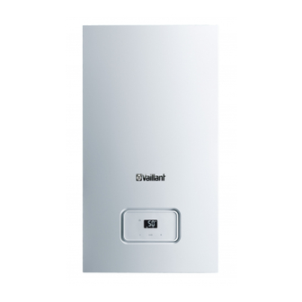
Summary of Contents for Vaillant HOME SYSTEM 12 -A
- Page 1 Operating instructions For the operator Operating instructions HOME SYSTEM GB, IE Publisher/manufacturer Vaillant GmbH Berghauser Str. 40 D-42859 Remscheid Tel. +49 21 91 18‑0 Fax +49 21 91 18‑28 10 info@vaillant.de www.vaillant.de...
-
Page 2: Table Of Contents
Contents Contents Care and maintenance ....13 Maintenance ........ 13 Safety ..........3 Caring for the product ....13 Action-related warnings ....3 Checking the condensate drain Intended use ........3 pipework and tundish....13 General safety information..... 4 Decommissioning...... 14 Notes on the documentation .. -
Page 3: Safety
Safety 1 1 Safety ral heating installations and for hot water generation. 1.1 Action-related warnings Intended use includes the fol- Classification of action-re- lowing: lated warnings – observance of the operating The action-related warnings instructions included for the are classified in accordance product and any other system with the severity of the pos- components... -
Page 4: General Safety Information
1 Safety communication systems in 1.3 General safety information the building. ▶ If it is safe to do so, close the 1.3.1 Installation by skilled emergency control valve or tradesmen only the main isolator. The installation, inspection, ▶ If possible, close the gas isol- maintenance and repair of the ator cock on the product. - Page 5 Safety 1 – to the gas, air, water and ▶ In order to operate the product, ensure that the con- electricity supplies – to the entire flue gas install- densate siphon is always full. ation 1.3.6 Risk of death due to –...
- Page 6 1 Safety ▶ Ensure that the supply of combustion air is always free of fluorine, chlorine, sulphur, dust, etc. ▶ Ensure that no chemical sub- stances are stored at the in- stallation site. 1.3.11 Risk of material damage caused by frost ▶...
-
Page 7: Notes On The Documentation
Notes on the documentation 2 2 Notes on the 3 Product description documentation 3.1 CE label 2.1 Observing other applicable documents ▶ You must observe all operating instruc- The CE label shows that the products tions enclosed with the system compon- comply with the basic requirements of the ents. -
Page 8: Product Design
3 Product description 3.4 Product design Information Meaning on the identi- fication plate Cat. Approved gas category Condensing Efficiency class of the boiler technology in accordance with EC Dir- ective 92/42/EEC Type: Xx3(x) Permissible flue gas connec- tions Maximum water pressure in heating mode Maximum water pressure in hot water handling mode... -
Page 9: Description Of The Display
Product description 3 3.6 Description of the display Symbol Meaning Heating mode – Permanently on: Heating mode activated – Flashing: Burner on in heating mode Display flashing: – Switching on the product – Fault Setting confirmed Operating in- Display showing Fault in the product formation the current heat-... -
Page 10: Operating Levels
4 Operation 3.8 Operating levels 4.2 Basic display The product has two operating levels: – The operator level shows the most im- portant information and offers set-up options which do not require any special prior knowledge. – Specialised knowledge is required in or- der to use the installer level (access for competent persons). -
Page 11: Filling The Heating Installation
Operation 4 4.4 Filling the heating installation 4.5 Selecting the operating mode Caution. Note The unit is always activated with Risk of material damage due the preselected operating mode. to heating water that is ex- tremely calciferous or corros- ▶ ive or contaminated by chem- Press repeatedly until the display... -
Page 12: Product Settings
4 Operation ◁ The main power supply is not inter- Conditions: Temperature controlled by the control- rupted. The product continues to be ler, with heating mode activated supplied with power. ▶ Set the maximum heating flow temper- ature on the boiler (→ Page 12). 4.10 Frost protection ▶... -
Page 13: Troubleshooting
Troubleshooting 5 6 Care and maintenance Conditions: If you are away from home for several days, With controller 6.1 Maintenance ▶ Program the number of days you will An annual inspection of the product carried be away in the controller to activate the out by a competent person is a prerequis- frost protection devices. -
Page 14: Decommissioning
The competent person who installed – Immediate help your product is responsible for the dis- If your Vaillant boiler develops a fault your posal of the packaging. first action should be to contact your in- staller, as his professional assessment is If the product is identified with this needed under the terms of our Guarantee. -
Page 15: Appendix
Appendix Appendix A Operator level – overview Setting level Values Unit Increment, select Factory set- tings Min. Max. Heating installation Pressure in the heating in- Current value stallation ℃ Heating flow temperature Current value Preset in the system B Troubleshooting Fault Cause Measure... - Page 16 Appendix Fault Cause Measure Product does not After three successive failed ignition Press the button. The product start up: attempts, the system switches to fault carries out a new ignition attempt. mode (fault code: F.28). If the ignition problem is not rec- –...
- Page 20 Nottingham Road Belper Derbyshire DE56 1JT Telephone 0330 100 3461 Telephone (renewables) 0207 022 0928 Vaillant Service Solutions 0330 100 3461 Spares Technical Enquiries 01773 596615 info@vaillant.co.uk technicalspares@groupservice.co.uk www.vaillant.co.uk © These instructions, or parts thereof, are protected by copyright and may be reproduced or distributed only with the manufacturer's written consent.


Need help?
Do you have a question about the HOME SYSTEM 12 -A and is the answer not in the manual?
Questions and answers