
Related Manuals for Power Walker VI 1000RT LCD


Summary of Contents for Power Walker VI 1000RT LCD
- Page 1 Line Interactive UPS PowerWalker VI 1000RT LCD PowerWalker VI 1500RT LCD PowerWalker VI 2000RT LCD PowerWalker VI 3000RT LCD Manual EN, DE...
- Page 2 IMPORTANT SAFETY INSTRUCTIONS SAVE THESE INSTRUCTIONS – This manual contains important instructions for models PowerWalker VI 1000/1500/2000/3000 RT LCD that should be followed during installation and maintenance of the UPS and batteries. • This product is specially designed for PCs and it is not recommended for use in any life-supporting system and other specific important equipment.
- Page 3 • Remove watches, rings, or other metal objects from the hand. • Use tools with insulated handles. • Servicing of batteries should be performed or supervised by personnel knowledgeable of batteries and the required precautions. Keep unauthorized personnel away from batteries. •...
-
Page 4: Table Of Contents
CONTENTS 1. Introduction ······························································································· 5 2. Safety Warning ··························································································· 2 2.1 Description of Commonly Used Symbols ····················································· 2 3. Installation ································································································· 3 3.1 Inspection of Unit ···················································································· 3 3.2 Unpacking the Cabinet ············································································· 3 3.3 UPS Setup ···························································································· 3 3.4 EBM Installation (Optional) ······································································· 8 3.5 UPS Initial Startup ·················································································... -
Page 5: Introduction
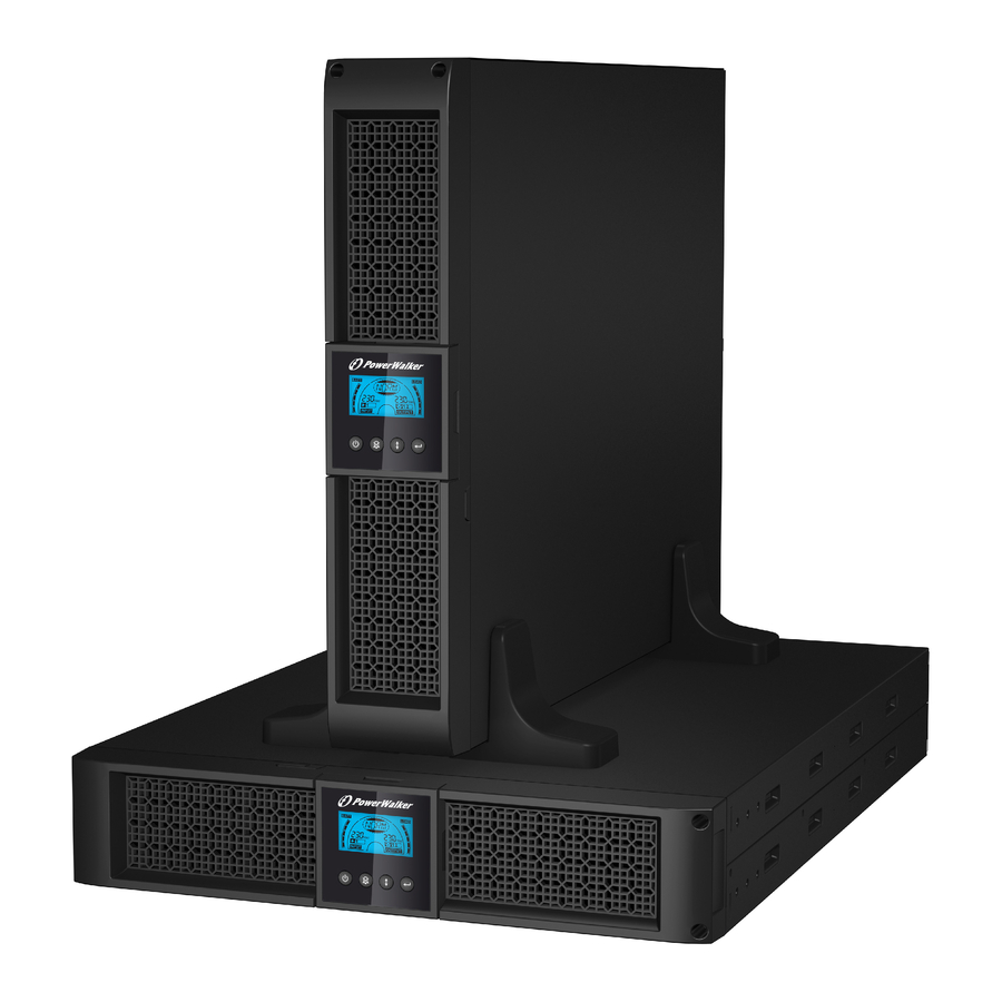
1. Introduction This line-interactive series is compact and pure sine wave UPS and it is designed for essential applications and environment, such as desktops, servers, workstations, and other networking equipments. These models are available in the output ratings of 1000VA, 1500VA, 2000VA and 3000VA. The series protects your sensitive electronic equipments against power problems including power sags, spike, brownouts, line noise, undervoltage, overvoltage and blackouts. -
Page 6: Description Of Commonly Used Symbols
Circuit Configuration Commonly used Symbols Following figure shows the basic internal circuit configuration of the UPS 2.1 Description of Commonly Used Symbols Some or all of the following Notations may be used in this manual and may appear in your application process. Therefore, all users should be familiar with them and understand their explanations. -
Page 7: Installation
3. Installation 3.1 Inspection of Unit Inspect the UPS upon receiving. If the UPS is apparently damaged during the shipment, please keep the box and packing material in original form for the carrier and notify the carrier and dealer immediately. 3.2 Unpacking the Cabinet To unpack the system: 1. - Page 8 Use the following procedure to install UPS in UPS stands. 1. Slide down the UPS vertically and put two UPS stands at the end of the tower. 2. Place down the UPS into two stands carefully.
- Page 9 3. Pull out the LCD box and rotate it in a clockwise direction to 90 degree and then push it back in the front panel.
- Page 10 Rack-mount setup The series can be installed in 19 inches racks. Both the UPS and external battery enclosure need 2U of valuable rack space. Use the following procedure to install UPS in a rack. 1. Align the mounting ears with screw holes on the side of the UPS, and tighten the screw.
- Page 11 3. Slide in the UPS into the rack rail and lock it in the rack enclosure. 4. Tighten the screw, and the load can then be connected.
-
Page 12: Ebm Installation (Optional)
3.4 EBM Installation (Optional) Connecting the EBM in Tower form: 1. Slide down the UPS and EBM vertically and place two UPS stands with the extend part at the end of the tower. 2. Tighten the screw on the metal sheet for stabilization 3. - Page 13 4. Take off the front panel, and connect the battery terminal (A) from UPS to EBM terminal (B) shown as below. Users need to remove the small gate(C) on side of the front panel to allow the outlet wire of the EBM to pass through the gate and then reassemble front panel.
- Page 14 2. Connect the earth line from UPS (port A ) to EBM (port B ) 3. Take off the LCD box, and unscrew the internal screws. Unscrew Unscrew...
- Page 15 4. Take off the front panel, and connect the battery terminal (A) from UPS to EBM terminal (B) shown as below. Users need to remove the small gate(C) on side of the front panel to allow the outlet wire of the EBM to pass through the gate and then reassemble front panel.
- Page 16 Connecting multiple EBMs in Tower form 1. Connect Earth line between UPS and the first EBM, and then connect Earth Line between the first EBM and the second EBM. 2. Take off the front panel, and connect the battery terminal (A) from UPS to EBM terminal (B) shown as below.
- Page 17 Connecting the Multiple EBMs in rack form 1. Connect Earth line between UPS and the first EBM, and then connect Earth Line between the first EBM and the second EBM. 2. Take off the front panel, and connect the battery terminal (A) from UPS to EBM terminal (B) shown as below.
-
Page 18: Ups Initial Startup
3.5 UPS Initial Startup To start up the UPS: 1. Verify that the internal batteries are connected. If optional EBMs are installed, verify that the EBMs are connected to the UPS. 2. Plug the equipment to be protected onto the UPS, but do not turn on the protected equipment. -
Page 19: Operation
4. Operation 4.1 Display Panel The UPS has a four-button graphical LCD with dual color backlight. Standard back-light is used to light up the display with black text and a blue background. When the UPS has a critical alarm, the backlight changes the background to red. - Page 20 The following table describes the functions of the LCD control buttons. Table2. Description of control button Control Switch Function Button --To turn on/off the UPS Press and hold the button more than 3 seconds. --To release the UPS from faulty mode ON/OFF Cut off input power and then press and hold the button...
- Page 21 LCD display functions: The following table describes the functions of the LCD display. Table3. Description of LCD display function Description Function Input frequency and Indicate the value of input frequency and voltage voltage Input plug indicator Light on when the input power is at no loss. Output frequency and Indicate the value of output frequency and voltage...
- Page 22 UPS Status Display String Description: The following table shows the description of the LCD display string: Table4. UPS Status Display String LCD Display String Description STbY UPS work at Standby mode IPVL Input voltage is too low IPVH Input voltage is too high IPFL Input frequency is too low IPFH...
-
Page 23: Operating Mode
4.2 Operating Mode Normal range mode: Under Input mode the UPS accepts AC input voltage range for +/-20%. Generator mode: Under generator mode, the low frequency transfer point can go as low as 40Hz and as high as 70Hz before being transferred to battery mode. -
Page 24: Configuring Ups For Ebm Numbers
6. Exit Settings mode: Press and hold the Enter button for 3 seconds or button for 0.5 second to exit setting mode. 4.4 Configuring UPS for EBM Numbers To ensure the LCD displays the correct battery volume, configure the UPS for the correct number of EBMs: 1. -
Page 25: Communication Port
5. Communication Port 5.1 RS-232 and USB Communication Ports To establish communication between the UPS and a computer, connect your computer to one of the UPS communication ports using an appropriate communication cable. When the communication cable is installed, power management software can exchange data with the UPS. -
Page 26: Network Management Card (Optional)
Caution: The EPO must not be connected to any utility connected circuits. Reinforced insulation to the utility is required. The EPO Switch must have a minimum rating of 24Vdc and 20mA and be a dedicated latching-type switch not tied into any other circuit. -
Page 27: Ups Maintenance
6. UPS Maintenance 6.1 UPS and Battery Care For the best preventive maintenance, keep the area around the UPS clean and dust-free. If the atmosphere is very dusty, clean the outside of the system with a vacuum cleaner. For long battery life, keep the UPS at an ambient temperature of 25°C (77°F) 6.2 Storing the UPS and Batteries When the UPS is intended to store for a long period, recharge the battery every 6... -
Page 28: Replacing Ups Internal Batteries
Do not dispose of battery in a fire. Batteries may explode when exposed to flame. Proper disposal of batteries is required. Refer to your local codes for disposal requirements. Do not open or mutilate the battery. Released toxic electrolyte is harmful to skin and eyes. - Page 29 4. Remove the right inner battery bracket. 5. Pull the battery pack out onto flat area. 6. Install new battery pack into UPS. 7. Screw up the battery bracket and reconnect the battery cable A and B 8. Re-install the front panel back to UPS.
-
Page 30: Testing New Batteries
6.5 Testing New Batteries For a battery test, please check: The batteries must be fully charged. The UPS must be in Normal mode with no active alarms. Don’t take on/off the load. To test batteries: 1. Connect the UPS to utility power for at least 48 hours to charge the batteries. 2. -
Page 31: Specification
7. Specification 7.1 Specification Table7. Electrical Specification 1000VA 1500VA 2000VA 3000VA Model Capacity Watt 900W 1350W 1800W 2700W Input voltage range 161-276VAC Input 50/60Hz ±5Hz for Normal Mode Frequency range 40-70Hz for Generator Mode Voltage 220/230/240VAC Voltage Regulation ±5% (Batt. Mode) Output Frequency 50Hz or 60Hz... - Page 32 Table8. Indicators and Audible alarm AC Mode NORM---normal mode Backup Mode Show “bATT” and sounding every 4 seconds Load/Battery Level LCD showing Indicator LCD show red screen and “ **** ” UPS Fault LCD show red screen and “ OVLD ” Overload LCD show red screen and “...
-
Page 33: Rear Panels
7.2 Rear Panels The UPS rear panel description table and pictures are shown as below: Function(1000VA &1500VA) AC Output Modem/Network Surge Protection Intelligent Slot for SNMP or AS/400 card AC Input RS232 / Dry-Contact Communication Port USB Port Earth Line Port INTERFACE OPTION RS232 1000VA &1500VA Standard &... - Page 34 I NTERFACE O PTI O N RS232 U SB 2000VA Standard model rear panel I N TERFACE O PTI O N RS232 U SB 2000VA Super charger model rear panel I N TERFACE O PTI O N RS232 U SB 3000VA Standard &...
- Page 35 The EBM rear panel description table and picture are shown as below: 36V &72V EBM) Function( Earth Line Port 36V &72V EBM rear panel...
-
Page 36: Trouble Shooting
8. Trouble Shooting 8.1 Audible Alarm Trouble Shooting Indication Cause Solution Sounding every 4 The UPS is on battery Check the input voltage seconds mode Sounding every The battery voltage is Save your work and turn off your Second and “bATL” on equipment screen Sounding every... -
Page 37: Software Installation
9. Software Installation WinPower is UPS monitoring software, featuring user-friendly interface to monitor and control your UPS. This unique software provides complete power protection for computer system while power failure. With the software users can monitor any UPS status on the same LAN. Furthermore, a UPS can provide security protection for more than one computer on the same LAN at the same time, such as shutting down system in security, saving application data and shutting down the UPS when power fails. - Page 38 Line Interactive USV PowerWalker VI 1000RT LCD PowerWalker VI 1500RT LCD PowerWalker VI 2000RT LCD PowerWalker VI 3000RT LCD Bedienungsanleitung EN, DE...
- Page 39 WICHTIGE SICHERHEITSHINWEISE BEWAHREN SIE DIESE ANLEITUNG GUT AUF – Dieses Handbuch enthält wichtige Anweisungen für die Modelle PowerWalker VI 1000/1500/2000/3000 RT LCD, die während Installation und Wartung der USV-Geräte und Akkus eingehalten werden müssen. • Dieses Produkt wurde speziell für PCs entwickelt und wird nicht für den Einsatz bei Lebenserhaltungssysteme und andere wichtige Geräte empfohlen.
- Page 40 • Ein interner Kurzschluss in dem USV-Gerät führt zu Gefahren wie z.B. Stromschlag oder Feuer. Um die Gefahr eines Stromschlages zu vermeiden, bitte niemals Flüssigkeitsbehälter (z.B. ein Wasserglas) auf dem USV-Gerät abstellen. • Werfen Sie die Batterie(n) nicht in offenes Feuer. Der Akku könnte explodieren. •...
- Page 41 • Verwenden Sie das Gerät nicht in einer der folgenden Umgebungen: Jegliche Bereiche mit brennbaren Gasen, ätzenden Substanzen oder hoher Staubbelastung. Jegliche Bereiche, in denen ungewöhnlich hohe oder niedrige Temperaturen vorherrschen (über 40 °C oder unter 0 °C) und mit einer Feuchtigkeit von mehr als 90%.
- Page 42 INHALT 1. EINFÜHRUNG ····························································································· 5 2. SCHALTUNGSKONFIGURATION UND HÄUFIG VERWENDETE SYMBOLE ········· 7 2.1 Description of Commonly Used Symbols ····················································· 7 3. INSTALLATION ··························································································· 8 3.1 ÜBERPRÜFUNG DES GERÄTS ································································ 8 3.2 AUSPACKEN DES SCHRANKS ································································ 8 3.3 USV-EINRICHTUNG ··············································································· 8 3.4 EBM-INSTALLATION (OPTIONAL) ··························································...
-
Page 43: Einführung
1. Einführung Diese Line-Interactive-Serie ist eine kompakte USV mit reiner Sinuswelle und ist für wichtige Anwendungen und Umgebungen wie Desktops, Server, Workstations und andere Netzwerk-Geräte konzipiert. Diese Modelle sind mit den Die Serie Leistungsstufen 1000VA, 1500VA, 2000VA und 3000VA erhältlich. schützt Ihre empfindlichen elektronischen Geräte gegen Probleme mit der Stromversorgung einschließlich... -
Page 44: Schaltungskonfiguration Und Häufig Verwendete Symbole
2. Schaltungskonfiguration und häufig verwendete Symbole Folgende Abbildung zeigt die grundlegenden interne Schaltungskonfiguration der 2.1 Beschreibung der häufig verwendeten Symbole In diesem Handbuch können einige oder alle der folgenden Notationen verwendet werden und in Ihrem Anwendungsprozess vorkommen. Deshalb sollten alle Anwender mit ihnen vertraut sein und ihre Erklärungen verstehen. Tabelle 1. -
Page 45: Installation
3. Installation 3.1 Überprüfung des Geräts Überprüfen Sie die USV bei Empfang. Wenn die USV während des Transport offensichtlich beschädigt wurde, bewahren Sie den Karton und das Verpackungsmaterial in der ursprünglichen Form für den Spediteur auf und benachrichtigen Sie sofort den Spediteur und den Händler. 3.2 Auspacken des Schranks Auspacken des Systems: 1. - Page 46 Gehen Sie folgendermaßen vor, um die USV in den USV-Ständern zu installieren. 1. Schieben Sie die USV senkrecht nach unten und stellen Sie zwei USV-Ständer am Ende des Towers auf. 2. Setzen Sie die USV vorsichtig in die zwei Ständer.
- Page 47 3. Ziehen Sie das LCD-Feld heraus, drehen Sie es im Uhrzeigersinn um 90 Grad und schieben Sie es in die Frontplatte zurück.
- Page 48 Rack-Montage Die Serie kann in 19-Zoll-Racks eingebaut werden. Sowohl die USV als auch externe Batteriegehäuse benötigen 2U wertvollen Platz im Rack. Gehen Sie folgendermaßen vor, um USV in einem Rack zu installieren. 1. Richten Sie die Montageösen an den Bohrungen an der Seite der USV aus und ziehen Sie die Schraube an.
- Page 49 3. Schieben Sie die USV in die Rack-Schienen und lassen Sie sie im Rack-Gehäuse einrasten. 4. Ziehen Sie die Schraube an, dann kann die Last angeschlossen werden.
-
Page 50: Ebm-Installation (Optional)
3.4 EBM-Installation (Optional) Anschließen des EBM bei Tower-Montage: 1. Schieben Sie USV und EBM senkrecht nach unten und setzen Sie zwei USV-Ständer mit dem verlängerten Teil auf das Ende des Towers. 2. Ziehen Sie zur Stabilisierung die Schraube auf dem Blech an 3. - Page 51 4. Nehmen Sie die Frontplatte ab und schließen Sie die Batterieklemme (A) von der USV wie unten dargestellt am EBM-Terminal (B) an. Benutzer müssen die kleine Tür (C) an der Seite der Frontplatte entfernen, damit der Ausgangsdraht des EBM durch die Tür verlegt werden kann, dann muss die Frontplatte wieder angebracht werden.
- Page 52 2. Verbinden Sie die Erdungsleitung von der USV (Anschluss A) mit dem EBM (Anschluss B) 3. Nehmen Sie das LCD-Feld und lösen Sie die inneren Schrauben. Unscrew Unscrew...
- Page 53 4. Nehmen Sie die Frontplatte ab und schließen Sie die Batterieklemme (A) von der USV wie unten dargestellt am EBM-Terminal (B) an. Benutzer müssen die kleine Tür (C) an der Seite der Frontplatte entfernen, damit der Ausgangsdraht des EBM durch die Tür verlegt werden kann, dann muss die Frontplatte wieder angebracht werden.
- Page 54 Anschließen mehrerer EBM bei Tower-Montage 1. Verbinden Sie die Erdungsleitung zwischen USV und dem ersten EBM, und dann die Erdungsleitung zwischen dem ersten und dem zweiten EBM. 2. Nehmen Sie die Frontplatte ab und schließen Sie die Batterieklemme (A) von der USV wie unten dargestellt am EBM-Terminal (B) an. Und verbinden Sie dann die Batterieklemme (D) vom ersten EBM mit der Batterieklemme (E) vom zweiten EBM.
- Page 55 Anschließen mehrerer EBM bei Rack-Montage 1. Verbinden Sie die Erdungsleitung zwischen USV und dem ersten EBM, und dann die Erdungsleitung zwischen dem ersten und dem zweiten EBM. 2. Nehmen Sie die Frontplatte ab und schließen Sie die Batterieklemme (A) von der USV wie unten dargestellt am EBM-Terminal (B) an. Und verbinden Sie dann die Batterieklemme (D) vom ersten EBM mit der Batterieklemme (E) vom zweiten EBM.
-
Page 56: Erstmalige Inbetriebnahme Der Usv
3.5 Erstmalige Inbetriebnahme der USV So wird die USV gestartet: 1. Stellen Sie sicher, dass die internen Batterien angeschlossen sind. Wenn optionale EBMs installiert werden, überprüfen Sie, ob die EBMs an die USV angeschlossen sind. 2. Stecken Sie die zu schützenden Geräte an der USV ein, aber schalten Sie diese Geräte nicht ein. -
Page 57: Betrieb
4. Betrieb 4.1 Anzeigefeld Die USV verfügt über eine Grafik-LCD mit vier Tasten und zweifarbiger Hintergrundbeleuchtung. Bei der Standard-Hintergrundbeleuchtung zeigt die Anzeige schwarzen Text und einen blauen Hintergrund. Wenn an der USV ein kritischer Alarm auftritt, wird der Hintergrund der Beleuchtung rot. Siehe Abbildung unten: Funktionen der Bedientasten: Es gibt auf dem Bedienfeld vier Tasten. - Page 58 Die folgende Tabelle beschreibt die Funktionen der LCD-Bedientasten. Tabelle 2. Beschreibung der Bedientaste Bedienta Schalter Funktion --Ein-/Ausschalten der USV Halten Sie die Taste mindestens 3 Sekunden gedrückt. ein/aus --Freigabe des Fehlerzustands der USV Stromzufuhr trennen und dann die Taste mehr als 2 Sekunden gedrückt halten, um die USV abzuschalten.
- Page 59 Funktionen der LCD-Anzeige: Die folgende Tabelle beschreibt die Funktionen der LCD-Anzeige. Tabelle 3. Beschreibung der Funktionen der LCD-Anzeige Beschreibung Funktion Eingangs-frequenz Geben Sie den Wert für Eingangs-frequenz und und spannung spannung an Leuchtet, wenn die Eingangsleistung keinen Eingangssteckeranzei Verlust aufweist. Ausgangs-frequenz Geben Sie den Wert für Ausgangs-frequenz und und spannung...
- Page 60 Text zur Beschreibung des USV-Status:Die folgende Tabelle enthält die Beschreibung des Texts der LCD-Anzeige: Tabelle 4. String USV-Statusanzeige String LCD-Anzeige Beschreibung STbY USV arbeitet im Bereitschaftsmodus (Standby-Modus) IPVL Eingangsspannung zu niedrig IPVH Eingangsspannung zu hoch IPFL Eingangsfrequenz zu niedrig IPFH Eingangsfrequenz zu hoch NORM USV arbeitet im Line-Modus...
-
Page 61: Betriebsmodus
4.2 Betriebsmodus Modus Normaler Bereich: Im Eingangsmodus akzeptiert die USV einen AC-Eingangsspannungsbereich von +/-20%. Generatormodus: Im Generator-Modus kann der Niedrigfrequenzgang bis auf 40Hz heruntergehen und bis auf 70Hz herauf, bevor der Übergang zum Batterie-Modus erfolgt. Modus Großer Bereich: In den Eingangseinstellungen akzeptiert die USV einen AC-Eingangsspannungsbereich für -30% ~ +20%. -
Page 62: Konfigurieren Der Usv Für Ebm-Nummern
Einstellungswert auszuwählen. Wählen Sie den Wert [001] oder [000], um das gewünschte Lastsegment auf ON oder OFF zu setzen. 5. Einstellungen bestätigen: Halten Sie die Taste Enter eine Sekunde gedrückt, dann kehrt die USV zum aktuellen Einstellungsobjekt zurück. 6. Einstellungsmodus beenden: Halten Sie die Taste Enter 3 Sekunden oder die Taste 0,5 Sekunden gedrückt, um den Einstellungsmodus zu... -
Page 63: Kommunikationsanschluss
4. Einstellungswert wählen: Drücken Sie die Taste Select , um "001" auszuwählen. 5. Einstellungen bestätigen: Halten Sie die Taste Enter eine Sekunde lang gedrückt, daraufhin kehrt die USV zum aktuellen Einstellungsobjekt zurück. 6. Einstellungsmodus beenden: Halten Sie die Taste Enter 3 Sekunden oder die Taste 0,5 Sekunden gedrückt, um den Einstellungsmodus zu... -
Page 64: Notabschaltung (Emergency Power Off, Epo)
5.2 Notabschaltung (Emergency Power Off, EPO) Die Notabschaltung (EPO) wird zum Abschalten der Last aus der Ferne verwendet. Diese Funktion kann zum Herunterfahren der Last im Notfall verwendet werden. Warnung: Diese Schaltung muss durch verstärkte Isolierung von gefährlichen Stromkreisen getrennt werden. Vorsicht: Die EPO darf nicht an Netzstromkreise angeschlossen werden. -
Page 65: Wartung Der Usv
6. Wartung der USV 6.1 Pflege von USV und Batterie Die beste vorbeugende Wartung ist, den Bereich um die USV sauber und staubfrei zu halten. Wenn die Atmosphäre sehr staubig ist, reinigen Sie die Außenseite der Anlage mit einem Staubsauger. Für eine lange Lebensdauer der Batterie stellen Sie die USV bei einer Umgebungstemperatur von 25°C auf. -
Page 66: Austauschen Der Batterien Im Inneren Der Usv
Wenn die Akkus ersetzt werden, ersetzen Sie diese mit dem gleichen Typ und der gleichen Anzahl Batterien oder Akkumulatoren. Wenden Sie sich an den Kundendienst, um neue Batterien zu bestellen. Werfen Sie die Batterien nicht ins Feuer. Batterien können explodieren, wenn sie Flammen ausgesetzt werden. - Page 67 4. Entfernen Sie die Halterung der rechten inneren Batterie. 5. Ziehen Sie die Batterie auf eine ebene Fläche heraus. 6. Setzen Sie die neue Batterie in die USV ein. 7. Schrauben Sie die Batteriehalterung an und schließen Sie die Batteriekabel A und B wieder an.
-
Page 68: Testen Neuer Batterien
6.5 Testen neuer Batterien Für einen Batterietest überprüfen Sie bitte Folgendes: Die Batterien müssen vollständig aufgeladen sein. Die USV muss sich im Normal-Modus ohne aktive Alarme befinden. Schalten Sie keine Last zu/ab. Testen der Batterien: 1. Schließen Sie die USV für mindestens 48 Stunden an das Stromnetz an, um die Batterien aufzuladen. -
Page 69: Spezifikation
7. Spezifikation 7.1. Spezifikation Tabelle 7. Elektrische Spezifikation 1000VA 1500VA 2000VA 3000VA Modell Kapazität Watt 900W 1350W 1800W 2700W Eingangsspannungs 161-276 V AC bereich Eingang 50/60Hz ±5Hz für Normal-Modus Frequenzbereich 40-70Hz für Generator-Modus Spannung 220/230/240VAC Spannungsregulieru ±5% Ausgang (Batt. -Modus) Frequenz 50 Hz oder 60 Hz Wellenform... - Page 70 Tabelle 8. Optischer und akustischer Alarm AC-Modus NORM---normaler Modus Anzeige “bATT” und akustisches Signal alle 4 Sicherungsmodus Sekunden Last-/Batterieniveau LCD-Anzeige Anzeige USV-Fehler LCD zeigt roten Bildschirm und “ **** ” Überlast LCD zeigt roten Bildschirm und “ OVLD ” Niedriger LCD zeigt roten Bildschirm und “...
-
Page 71: Rückseiten
7.2 Rückseiten Der Tabelle mit der Beschreibung der Rückseite der USV und Abbildungen werden wie unten dargestellt: Funktion(1000VA &1500VA) AC-Ausgang Überspannungsschutz Modem/Network Intelligenter Einschub für SNMP- oder AS/400-Karte AC-Eingang RS232 / Kommunikationsanschluss mit Trockenkontakt USB Schnittstelle Schutzleiteranschluss INTERFACE OPTION RS232 1000VA &1500VA Standard- &... - Page 72 I NTERFACE O PTI O N RS232 U SB 2000VA Standard-Modell, Rückseite I N TERFACE O PTI O N RS232 U SB 2000VA Supercharger-Modell, Rückseite I N TERFACE O PTI O N RS232 U SB...
- Page 73 3000VA Standard- & Supercharger-Modell, Rückseite Die Tabelle mit der Beschreibung der EBM-Rückseite und Abbildungen werden wie unten dargestellt: 36V &72V EBM) Funktion( Schutzleiteranschluss 36V &72V EBM-Rückseite...
-
Page 74: Fehlerbehebung
8. Fehlerbehebung 8.1 Fehlerbehebung bei akustischem Alarm Anzeige Ursache Lösung Ertönt alle 4 Sekunden Die USV ist im Eingangsspannung prüfen Batteriemodus Ertönt jede Sekunde Arbeit speichern und Geräte und "bATL" wird Batteriespannung niedrig ausschalten angezeigt Ertönt jede Sekunde Lastniveauanzeige prüfen und etwas und "OVLD"... -
Page 75: Softwareinstallation
9. Softwareinstallation WinPower ist die Überwachungssoftware der USV, mit benutzerfreundlicher Schnittstelle zur Überwachung und Steuerung Ihrer USV. Diese einzigartige Software bietet kompletten Leistungsschutz für Ihr Computer-System bei Stromausfall. Mit der Software können Benutzer jeden USV-Status auf dem gleichen LAN überwachen. Darüber hinaus kann eine USV Sicherheits für mehr als einen Computer auf dem gleichen LAN gleichzeitig liefern, z.B.
Need help?
Do you have a question about the VI 1000RT LCD and is the answer not in the manual?
Questions and answers